GEOMETRICAL OPTICS, Class 12, Physics (IIT-JEE & AIPMT) Chapter Notes PDF Download
Geometrical Optics
1. Properties of light
(i) Speed of light in vaccum, denoted by c, is equal to 3 × 10⁸ m/s approximately
(ii) Light is electromagnetic wave (proposed by Maxwell). It consists of varying electric field and magnetic field.
(iii) Light carries energy and momentum.
(iv) The forcula v = fλ is applicable to light.


2. Ray optics
Ray optics treats propagation of light in terms of rays and is valid only if the size of the obstacle is much greater than the wavelength of light. It concern with the image formation and deals with the study of the simply facts such as rectilinear propagation, laws of reflection and refraction by geometrical methods.
2.1 Ray :
A ray can be defined as an imaginary line drawn in the direction in which light is travelling. Light behaves as a stream of energy propagated along the direction of rays. The rays are directed outward from the source of light in straight lines.
2.2 Beam of Light :
A beam of light is a collection of these rays. There are mainly three types of beams.
(i) Parallel beam of light :
A search light and the headlight of a vehicle emit a parallel beam of light. The source of light at a very large distance like sun effectively gives a parallel beam. 
(ii) Divergent beam of light :
The rays going out from a point source generally form a divergent beam.
(iii) Convergent beam of light :
A beam of light that is going to meet (or converge) at a point is known as a convergent beam. A parallel beam of light after passing through a convex lens becomes a convergent beam.
3. Reflection
When a ray of light is incident at a point on the surface, the surface throws partly or wholly the incident energy back into the medium of incidence. This phenomenon is called reflection.
Surfaces that cause reflection are known as mirrors or reflectors. Mirrors can be plane or curved.


In the above figures,
O is the point of incidence, AO is the incident ray,
OB is the reflected ray, ON is the normal at the incidence.
Angle of incidence : The angle which the incident ray makes with the normal at the point of incidence is called the angle of incidence. It is generally denoted by 'i'.
Angle of reflection : The angle which the reflected ray makes with the normal at the point of incidence is called the angle of reflection. It is generally denoted by 'r'.
Glancing angle : The angle which the incident ray makes with the plane reflecting surface is called glancing angle. It is generally denoted by 'g'.
g = 90°- i ...(1)
3.1 Law of reflection
(i) The incident ray, the reflected ray and the normal to the reflecting surface at the point of incidence, all lie in the same plane.
(ii) The angle of incidence is equal to the angle of reflection, i.e.,
These laws hold good for all reflecting surfaces either plane or curved.
Some important points
(i) If  , i.e., if a ray is incident normally on a boundary, after reflection it retraces its path.


(ii) None of the frequency, wavelength and speed changes due to reflection. However, intensity and hence amplitude (I is directly proportional to A2) usually decreases.

(iii) If the surface is irregular, the reflected rays on an incident beam of parallel light rays will be in random direction. Such an irregular reflection is called diffused reflection.
4. Plane Mirror
Plane mirror is formed by polishing one surface of a plane thin glass plate. It is also said to be silvered on one side.

PLANE MIRROR
A beam of parallel rays of light, incident on a plane mirror will get reflected as a beam of parallel reflected rays.
Formation of image by a plane mirror.
from the argument of similar triangles OM = IM i.e., perpendicular distance of the object from the mirror = perpendicular distance of the image from the mirror.
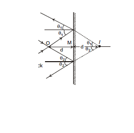
Steps to draw the image :
(1) Drop a perpendicular on the mirror and extend it on the back side of the mirror.
(2) Image always lie on this extended line
(3) To exactly locate the image, use the concept :
Perpendicular distance of the object from the mirror is equals to the perpendicular distance from the mirror of the image.

Ex.1 A mirror is inclined at an angle of 45° with the horizontal and mirror starts from the origin, an object is kept at x = - 2 cm. Locat its image
Sol.

4.1 Image of an extended linear object :
Draw the images of the extreme points and joined them with a straight line

Properties of image of an extended object, formed by a plane mirror :
(1) Size of extended object = size of extended image.
(2) The image is erect, if the extended object is placed parallel to the mirror.

(3) The image is inverted if the extended object lies perpendicular to the plane mirror.


(4) If an extended horizontal object is placed infront of a mirror inclined 45º with the horizontal, the image formed will be vertical. See figure.

(i)  (ii)
(ii) 
Ex.2 An unnumbered wall clock show time 8 : 12 where 1st term represent hours, 2nd represent minutes. What time will its image in plane mirror show.
Sol. 
Image shows 3 : 48
Short trick
Draw watch on paper and then see it from reverse side.
4.2 Field of view :
Area in which reflected rays exists is called field of view. It is the area from which an observer can see the image of an object. If the observer is outside this area he will not be able to see the image although the image will be there.


Ex.3 A man is travelling on the rod along AB. Find out the length of the road for which the image will be visible to him.
(A) l (B) 3l
(C) 1.5 l (D) 2l
Sol. In the ray diagram shown
Δ AQC ~ Δ DMC
 =
=  ⇒ x =
⇒ x = 
Therefore, Total length =  (option = B)
 Most of the problems in optics involving geometry can be solved by using similar triangles.
4.3 Field of view of extended linear object
Common field of view of extreme points of the object will be the field of view of extended linear object.
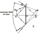
4.4 Relation between velocity of object and image :
From mirror property :
xim =- xom, yim = yom and zim = zom
Here xim means 'x' coordinate of image with respect to mirror.
Similarly others have meaning.
Differentiating w.r.t time, we get
v(im)x =- v(om)x ; v(im)y = v(om)y ; v(im)z = v(om)z
⇒ for x axis viG - vmG =- (voG - vmG)
⇒ vmG = 
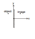
here : viG = velocity of image with respect to ground
vOG = velocity of object with respect to ground.
vmg = velocity of mirror with respect to ground.
 Valid only for perpendicular component of velocity to the mirror.
Ex.4 An object moves with 5 m/s towards right while the mirror moves with 1 m/s towards the left as shown. Find the velocity of image.
Sol. Take → as + direction. vi - vm = vm - v0
⇒ vi - (-1) = (-1)- 5
Therefore, vi =- 7m/s
⇒ 7 m/s and direction towards left.
Ex.5 In the situation shown in figure, find the velocity of image.

Sol. Along x direction, applying vi - vm =- (v0 - vm)
vi - (- 5 cos 30°) =- (10 cos 60°- (-5 cos 30°)) Therefore, v1 =- 5 (1 +  ) m/s
) m/s
Along y direction v0 = vi Therefore, vi = 10 sin 60° =  m/s
m/s
Therefore, Velocity of the image =- 5 (1+  )
) + m/s
+ m/s
4.5 Deviation produced by a Plane mirror
Deviation is defined as the angle between directions of the incident ray d the reflected ray (or, the emergent ray). It is generally denoted by d.

Here, 
or,  = 180°- 2 i
Ex.6 Two plane mirrors are inclined at an angle q with each-other. A ray of light strikes one of them. Find its deviation after it has been reflected twice-one from each mirror.
Sol. Case I :

 = clockwise deviation at A = 180°- 2 i1
 = anticlockwise deviation at B = 180°- 2i2
Now, from Δ OAB, we have

Δ + (90°- i1) + (90° + i2) = 180°
⇒ i1 - i2 = θ
As i1 > i2, 
Hence, the net angle anticlockwise deviation =  = (180°- 2i2)- (180°- 2i1)
= 2(i1 - i2) = 2θ
Case : II
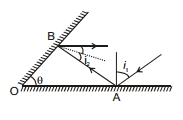
 = clockwise deviation at A = 180°- 2 i1
 = clockwise deviation at B = 180°- 2 i2
Now, from Δ OAB, we have
or, θ + (90°- i1 ) + (90°- i2) = 180°
⇒ i1 + i2 = θ
Hence, net clockwise deviation = 
= (180°- 2i2) + (180°- 2i1)
= 360°- 2(i1 + i2)
= 360°- 2θ
⇒ Net anticlockwise deviation = 360°- (360°- 2θ) = 2θ
Ex.7 Find out the angle of deviation

Sol. Angle of deviation = 90°
Ex.8 Find out the angle of deviation

Sol.
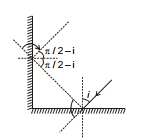
 = For Ist reflection
= π - 2i (clockwise)
 = For 2nd reflection
= π -  (clockwise) = 2i

= π - 2i + 2i = π
4.6 Real or virtual image/Object
Object and Image
Object is defined as point of intersection of incident rays. Image is defined as point of intersection of reflected rays (in case of reflection) or refracted rays (in case of refraction).


5. Rotation of Mirror
For a fixed incident light ray, if the mirror be rotated through an angle θ (about an axis which lies in the plane of mirror and perpendicular to the plane of incidence), the reflected ray turns through an angle
2θ in same sense.
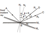
See figure M1, N1 and R1 indicate the initial position of mirror, initial normal and initial direction of reflected light ray respectively. M2, N2 and R2 indicate the final position of mirror, final normal and final direction of reflected light ray respectively. From figure it is clear that 
Ex.9 By what angle the mirror must be rotated such that the reflected ray becomes vertical.

Sol. The diagram below shows the four ways in which the reflected ray can become vertical.
For case 1 :
Angle by which the Reflected ray rotates = 30°
Angle by which the mirror rotates =  = 15°
= 15°
(Anticlokwise)
For case 2 :
Angle by which the Reflected ray rotates = 150°
Angle by which the mirror rotates = 75°
(clockwise)
For case 3 :
Angle by which the Reflected ray rotates = 300°
Angle by which the mirror rotates = 150°
(clockwise)
For case 4 :
Angle by which the Reflected ray rotates = 210°
Angle by which the mirror rotates = 105°
(Anticlokwise)
But case (2) & case (3) are not possible as the I.R. falls on the polished part of mirror. after rotation of mirror.
Therefore, Answer is 15° (Anticlockwise) and 105° (Anticlockwise)
Ex.10 A mirror is placed at the centre of a sphere and it is rotating with an angular speed w. Incident light falls on the mirror at the centre of the sphere. Find out the linear speed of the light spot on the sphere?

Sol. Angular speed of mirror = 
Angular speed of Reflected Ray =
Speed of light spot on the mirror :
Ex.11 In the previous question instead of spherical wall there is a vertical wall at a perpendicular distance d from the point & where the light is incident.
Sol.
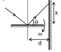
tanθ =  ⇒ x = d tan θ


OR
Considering an instantaneous circle of radius dsecθ.
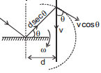
vt = 2ωdsecθ (2ωdcosθ is a component of v.)
v cos θ = 2ωdsecθ
⇒ v =  = 2ωd sec2θ
6. Images formed by two plane mirrors
If rays after getting reflected from one mirror strike second mirror, the image formed by first mirror will function as an object for second mirror, and this process will continue for every successive reflection.
6.1 Images due to parallel plane mirrors :
Ex.12 Figure shows a point object placed between two parallel mirrors. Its distance from M1 is 2 cm and that from M2 is 8 cm. Find the distance of images from the two mirrors considering reflection on mirror M1 first.

Sol. To understand how images are formed see the following figure and table.
You will require to know what symbols like I121 stands for. See the following diagram.


Similarly images will be formed by the rays striking mirror M2 first. Total number of images =∞.
Ex.13 Two plane mirrors are kept parallel to each other at a distance of 2 cm. An object is kept at the midpoint of the line joining them. Locate the images by drawing appropriate Ray diagram.
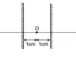
Sol. 
Thus, it forms an A.P.
Ex.14 Consider two perpendicular mirrors. M1 and M2 and a object O. Taking origin at the point of intersection of the mirrors and the coordinate of object as (x, y), find the position and number of images.
Sol. Rays 'a' and 'b' strike mirror M1 only and these rays will form image I1 at (x,-y), such that O and I1 are equidistant from mirror M1. These rays do not form further image because they do not strike any mirror again. Similarly rays 'd' and 'e' strike mirror M2 only and these rays will form image I2 at (-x, y), such that O and I2 are equidistant from mirror M2.
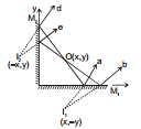
Now consider those rays which strike mirror M2 first and then the mirror M1.
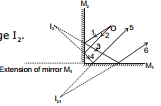
For incident ray 1,2 object is O, and reflected rays 3, 4 from image I2.
Now rays 3, 4 incident on M1 (object is I2) which reflect as rays 5, 6 and form image I21. Rays 5, 6 do not strike any mirror, so image formation stops.
I2 and I21, are equidistant from M1. To summarize see the following figure Now rays 3,4 incident on M1 (object is I2) which reflect as rays 5, 6 and form image I21. Rays 5, 6 do not strike any mirror, so image formation stops.
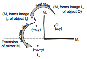
For rays reflecting first from M1 and from M2, first image I1 at (x,-y)) will be formed and this will function as object for mirror M2 and then its image I12 (at (-x,-y)) will be formed. I12 and I21 coincide.
Therefore, Three images are formed.
6.2 Locating all the Images formed by two Plane Mirrors :
Consider two plane mirrors M1 and M2 inclined at an angle θ = α + β as shown in figure. Point P is an object kept such that it makes angle a with mirror M1 and angle b with mirror M2. Image of object P formed by M1, denoted by I1, will be inclined by angle a on the other side of mirror M1. This angle is written in bracket in the figure besides I1. Similarly image of object P formed by M2., denoted by I2, will be inclined by angle b on the other side of mirror M2. This angle is written in bracket in the figure besides I2.
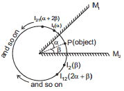
Now I2 will act as an object for M1 which is at an angle (α + 2β) on the opposite site of M1. This image will be denoted I21, and so on. Think when this will process stop [Hint : The virtual image formed by a plane mirror must note be in front of the mirror of its extension.]
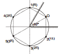
6.3 Circle concept
All the images formed will lie on a circle whose centre is the intersection point of the mirror and radius equal to distance of object from the intersection point.
7. Number of images formed by two inclined mirrors.
(i) if  = even number.; number of image =
(ii) If  = odd number ; number of image
  ,
,
If the object is placed on the angle bisector.
(iii) If  = odd number ; number of image =
  ,
,
If the object is not placed on the angle bisector.
(iv) If  , then the number of images = nearest even integer.
Ex.15 Two mirrors are inclined by an angle 30°. An object is placed making 10° with the mirror M1. Find the positions of first two images formed by each mirror. Find the total number of images using (i) direct formula and (ii) counting the images.
Sol. Figure is self explanatory.
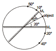
Number of images
(i) Using direct formula : 
Therefore, number of images = 12- 1 = 11
(ii) By counting. see the following table
To check whether the final images made by the two mirrors coincide or not : add the last angles and the angle between the mirrors. If it comes out to be exactly 360°, it implies that the final images formed by the two mirrors coincide. Here last angles made by the mirrors + the angle between the mirrors = 160° + 170° + 30° = 360°. Therefore in this case the last imagescoincide. Therefore the number of images = number of images formed by mirror M1 + number of images formed by mirror M2- 1 (as the last images coincide) = 6 + 6- 1 = 11.

8. MINIMUM LENGTH OF THE MIRROR TO SEE FULL IMAGE.
Ex.16 Show that the minimum size of a plane mirror, required to see the full image of an observer is half the size of the observer.
Sol. See the following figure. It is self explanatory if you consider lengths 'x' and 'y' as shown in figure.

Aliter :
ΔE M1, M2 and ΔE H' F' are similar
Therefore,  =
= 
or M1 M2 = H´ F´ / 2 = HF / 2
Ex.17 Show the Part of the image which man can see in the mirror as shown in the figure.

Sol. 
Vector - Form
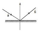
 = Unit vector along the incident ray
 = Unit normal vector
= Unit vector along the reflected Ray

9. SPHERICAL MIRROR
9.1 Some Important Definitions.
(i) Spherical Mirrors :


(ii) Paraxial Rays : The ray which have very small angle of incidence are known as paraxial rays.
(iii) Pole or Vertex : It is a point on the mirror from where it is easy to measure object and image distance.

In the above figure, the point P is the pole.
(iv) Centre of curvature : The centre C of the sphere of which the sperical mirror is a part, is the centre of curvature of the mirror.
(v) Radius of curvature (R) : Radius of curvature is the radius R of the sphere of which the mirror forms a part.

(vi) Principal axis :


Line joining pole and centre of curvature of the mirror is known as principle axis or optical axis.


If θ is very small : 
(vii) Focus (F) : If the rays are parallel to principla axis and paraxial then the point of which they appear to converge is known as focus. Distance of focus from pole then be R/2


concave mirror
(viii) Focal Length (f) : Focal length is the distance PF between the pole P and focus F along the principal axis.
(ix) Aperture : The line joining the end points of a spherical mirror is called the aperture or linear aperture.


(x) Focal plane : - Plane passing through focus and perpendicular to the optical axis called focal plane.
Ex.18 Find distance on focal plane where parallel and paraxial rays which are not parallel to optic axis, meet after reflection.
Sol. In ΔFF´P tan θ = 
h = f θ (θ is small)
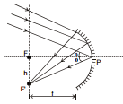
 If the rays are parallel and paraxial but not parallel to optic axis then they will meet at focal plane.
Ex.19 Find the angle of incidence of ray for which it passes through the pole, given that MI || CP.
Sol.

 = θ
= θ
MI || CP 
CI = CP = R

Therefore, In ΔCIP all angle are equal
3θ = 180° ⇒ θ = 60°
Ex.20 Find the distance CQ if incident light ray parallel to principal axis is incident at an angle i. Also find the distance 

Sol. cos i =  ⇒ CQ =

As i increases cos i decreases.
Hence CQ increases
So, paraxial rays meet at a distance equal to R/2 from centre of curvature, which is called focus, Principal focus (F) is the point of intersection all the reflected rays for which the incident rays strike the mirror (with small aperture) parallel to the principal axis. In concave mirror it is real and in the convex mirror it is virtual. The distance from pole to focus is called focal length. Aperture (related to the size of mirror) is the diameter of the mirror.


Concave mirror Convex mirror
9.2 RULES FOR IMAGE FORMATION
The reflection of light rays and formation of images are shown with the help of ray diagrams. Some typical incident rays and the corresponding reflected rays are shown below.
(i) A ray passing parallel to the principal axis, after reflection from the spherical mirror passes or appears to pass through its focus (by the definition of focus)


(ii) A ray passing through or directed towards focus, after reflection from the sperical mirror becomes parallel to the principal axis (by the principal of reversiblity of light).


(iii) A ray passing through or directed towards the centre of curvature, after reflection from the spherical mirror, retraces its path (as for it Ði = 0 and so Ð r = 0)


(iv) It is easy to make the ray tracing of a ray incident at the pole as shown in below.

9.3 RELATION BETWEEN u, v AND R FOR SPHERICAL MIRRORS
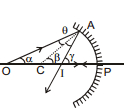
Consider the situations shown in figure. A point object is placed at the point O of the principal axis of a concave mirror. A ray OA is incident on the mirror at A. It is reflected in the direction AI. Another ray OP travels along the principal axis. As PO is normal to the mirror at P, the ray is reflected back along PO. The reflected rays PO and AI interesect at I where the image is formed.
Let C be the centre of curvature. The line CA is the normal at A. Thus, by the laws of reflection,  Let α, β, γ and θ denote the angles AOP, ACP, AIP and OAC respectively. As the exterior angle in a triangle equals the sum of the two opposite interior angles, we have,
from triangle OAC β = α + θ ....(i)
and from triangle OAI γ = α + 2θ. ...(ii)
Eliminating θ from (i) and (ii),
2β = α + γ. ...(iii)
If the point A is close to P, the angles α, β and γ are small and we can write
α =  , β =
, β =  and γis not equal to
  . or,
. or,  ...(iv)
The pole P is taken as the origin and the principal axis as the X-axis. The rays are incident from left to right. We take the direction from left to right as the positive X-direction. The points O, I and C are situated to the left of the origin P in the figure. The quantities u, v and R are, therefore, negative. As the distances PO, PI and PC are positives, PO =- u, PI =- v and PC =- R. Putting in (iv),
 or,
or,  ...(vii)
Although equation (vii) is derived for a special situation shown in figure, it is also valid in all other situations with a spherical mirror. This is because we have taken proper care of the signs of u, v and R appearing in figure shown.


9.4 sign convention
(i) All distances are measured from the pole of the spherical mirror along the principal axis. (Pole is considered as origin)
(ii) Distances measured along the principal axis in the direction of the incident ray are taken to be positive while the distance measured along the principal axis against the direction of the incident ray are taken to be negative.
(iii) Distances measured above the principal axis are taken to be positive while distances measured below the principal axis are taken to be negative.
Ex.21 


Important Points Regarding Sign Convention :
(i) If the point (i) is valid, or convention concides with right hand co-ordinate (or new Cartesian co-ordinate system). If the point (i) is not
(ii) In this sign convention, focal length of a concave mirror is always negative while the focal length of a convex mirror is always positive.
Assume the pole to be (0, 0).
Ex.22 Find out the position and type of image formed.

Sol. 


 cm
cm
V =- 15cm (Real image)
Ex.23 Find out the position and type of image formed.

Sol. 


Therefore, V = + 10 (Virtual image)
9.5 MAGNIFICATION :
9.5.1 Transverse Magnification
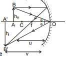
Δ ABO ~ Δ A'B'O
x =  ⇒ m =
⇒ m = 
* The above formula is valid for both concave and convex mirror.
* Above the optical axis is considered positive and below to be negative
* hi, h0, v and u should be put with sign.
9.5.2 In case of successive reflection from mirrors, the overall lateral magnification is given by m1 × m2 × m3 .........., where m1, m2 etc. are lateral magnication produced by individual mirrors.
Note
Using above relation, following conclusion can be made (check yourself).
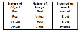
9.5.3 From previous; we get m =  ...........
(just a time saving formula)
Ex.24 Findout the position, height and type of image.

Sol.
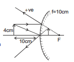


 ⇒ V = + 5cm

9.6 Cases for image formation by concave mirror.
(i) When the object is at infinity

The image is formed at F. It is real, inverted and highly diminished.
(ii) When the object lies beyond C (i.e., between infinity and C)

The image is formed between F and C. It is real, inverted and diminished.
(iii) When the object lies at C

The image is formed at C it is real inverted and of same size.
(iv) When the object lies between F and C

The image is formed beyond C (i.e., between C and infinity). It is real, inverted and enlarged.
(v) When the object is at F.

The image of formed at infinity. It is real, inverted and highly enlarged.
(vi) When the object lies between P and F

The image is formed behind the concave mirror. It is virtual, erect and enlarged.
9.7 Longitudinal Magnification

By differentiating
⇒  ⇒
⇒ 
Longitudinal magnification when the size of object is quite less with respect to its distance from the pole.
Above formula is valid only when the length of object is very small as compared to the distance of object from the pole.
dv → length of image
du → length of object
u → object distance from the pole.
v → Image distance from the pole.
Ex.25 Show the approximate image of AB in following cases.
(i)  ⇒
⇒ 
(ii)  ⇒
⇒ 
9.8 Cases for image formation by convex mirror.
(i) When the object is at infinity
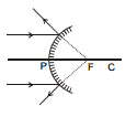
The image is formed at F. It is virtual, erect and highly diminished.
(ii) When the object lies in between infinity and P

The image is formed between P and F. It is virtual, erect and diminished.
In case of image formation unless states otherwise, object is taken to be real and we consider only rays that are close to the principal axis and that make small angles with it. Such rays are called paraxial rays. In practice this condition may be achieved by using a mirror whose size is much smaller than the radius of curvature of the surface. Otherwise the image will be distorted.


FOR CONCAVE MIRROR For convex mirror
9.9 Velocity in Spherical Mirror :
Velocity of image
(a) Object moving along principal axis :
On differentiating the mirror formula with respect to time we get  where
where  is the velcoity of image along Principal axis and
  is the velocity of the object along Principal axis. Negative sign implies that the image, in case of mirror, always moves in the direction opposite to that of object. This discussion is for velocity with respect to mirror and along the x axis.
Hence above equation can be written as 
Ex.26 Find velocity of image in the given figure.
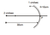
Sol. Here u =- 30 cm
f =- 10 cm
From using mirror formula
v =- 15 cm

VI - (- 1) =  ⇒ VI =-
  cm/sec.
(b) Object moving perpendicular to principal axis :
From the magnification formula we have,
 or
or 
If a point object moves perpendicular to the principal axis, x coordinate of both the object & the image become constant. On differentiating the above relation w.r.t time, we get,

Here,  = v0 denotes velocity of object perpendicular to the principal axis and
  = vy denotes velocity of image perpendicular to the principal axis.
(c) Object moving parallel to Principal axis :
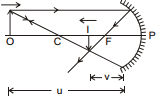
vx = 
On differentiating equation hi =

Ex.27 A gun of mass m1 fires a bullet of mass m2 with a horizontal speed v0. The gun is fitted with a concave mirror of focal length f facing towards a receding bullet. Find the speed of separations of the bullet and the image just after the gun was fired.

Sol. Let v1 be the speed of gun (or mirror) just after the firing of bullet.
From conservation of linear momentum.
m2v0 = m1v1
or v1 = ...(i)
Now,  = rate at which distance between mirror and bullet is increasing
= v1 + v0 ...(ii)
Therefore,  Here
Here 
(as at the time of firing bullet is at pole)

 ...(iii)
Here  is the rate at which distance between image (of bullet) and mirror is increasing. So if v2 is the absolute velocity of image (towards right) then,
 or v2 = 2v1 + v0 ...(iv)
Therefore, speed of separation of bullet and image will be,
vr = v2 + v0 = 2v1 + v0 + v0 or vr = 2 (v1 + v0)
Substituting value of v1 from equation (i) we have,
vr =  Ans.
Ans.
10. CUTTING OF MIRRORS


Both the part of mirror have same hollow sphere so its radius of curvature is same therefore no of images found is 1.
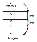
If we cut the mirror and shift it the centre of curvature changes for example in the figure shown below. A concave mirror is cut and each part is shifted by 1mm. Then centre of curvature of each part shift by 1mm and each part behaves as 2 independent concave mirror with its centre of curvature at the new position.
Therefore two images are found.
10.1 Field of View :

Ex.28 Figure shows a spherical concave mirror with its pole at (0, 0) and principal axis along x axis. There is a point object at (-40 cm, 1 cm), find the position of image.
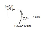
Sol. According to sing convention,
u =- 40 cm, h1 = + 1 cm, f =- 5 cm
 ⇒
⇒  ; v =
; v =  ;
; 
⇒ h2 =-  =
=  =-
=-  cm.
cm.
Therefore, The position of image is 
11. Combination of mirrors.
Ex.29 Find the position of final image after three successive reflections taking first reflection on m1.

Sol. I reflection:
Focus of mirror =- 10 cm ⇒ u =- 15 cm
Applying mirror formula :
 ⇒ v =- 30 cm
For II reflection on plane mirror :
u =- 10 cm Therefore, v = 10 cm
For III reflection on curved mirror again :
u =- 50 cm, f =- 10 cm
Applying mirror formula :
 ⇒ v =- 12.5 cm
Ex.30 Find out the position of the final image formed by two reflections. Take the first reflection from M1.

Sol.

For M1

⇒  ⇒
⇒  ⇒ v = + 5 cm
For M2 : u =-60, f =- 20

⇒  ⇒
⇒  ⇒ v =- 30 cm
Ex.31 Find out the position of the final image formed by two reflections. Take the first reflection from M1.

Sol. For M1 :
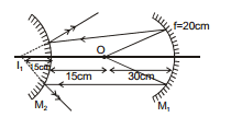
u =- 30, f =- 20

⇒ v =- 60 cm
For M2 :
u = + 15, f = + 10, v = + 30
 Reversibility of Rays.
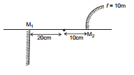
Ex.32 Find out the number and positions of all the images formed in the figure shown below.
Sol.

For M2 :
u =- 10 cm, f = + 10 cm, v = + 5 cm
Note : In the above case only one ray will go on the optic axis and the one ray is not responsible for image formation.
12. Intensity of light
Ex.33 intensity at A due to source is I. Without concave mirror, then find out the intensity of A after placing concave mirror.
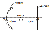
Sol.
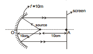


⇒ 
⇒ v = ∞
Intensity at A due to reflection = I.
Total = I + I = 2I
Ex.34 Intensity at A due to source is I. Without concave mirror, then find out the intensity of A after placing concave mirror.
(I) 
Sol.
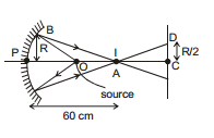
P = I × 
Intensity at P =  =
=  = 4I
= 4I
Now Δ PAB ~ ΔACD
⇒ 
⇒ CD =  =
= 
Energy at Area of R radius = 4 I × πR2
Now energy will fall on the screen but at an Area of radius
So intensity from mirror =  = 16 I
Total Intesity = 16 I + I = 17 I
(ii) 
Sol.
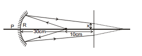
P = I × 
Intensity at P =  =
= 
Now 
x = 
Power incident on mirror
PP = 
this power will be incident on px2 area
So Intensity from mirror = 
So total I = I + I = 2I
13. Refraction of Light
Deviation or bending of light rays from their original path while passing from one medium to another is called refraction. It is due to change in speed of light as light passes from one medium to another medium. If the light is incident normally then it goes to the second medium without bending, but still it is called refraction.
Refractive index of a medium is defined as the factor by which speed of light reduces as compared to the speed of light in vacuum.
μ =  =
= 
More (less) refractive index implies less (more) speed of light in that medium, which therefore is called denser(rarer) medium.

Higher the value of Refractive index denser (optically) is the medium.
Frequency of light does not change during refraction
Refractive index of the medium relative to vacuum
= 
nvacuum = 1 ; nair  1 ;
1 ;
nwater (average value) = 4/3 ;
ngiass (average value) = 3/2
13.1 Laws of Refraction :
(a) The incident ray, the normal to any refracting surface at the point of incidence and the refracted ray all lie in the same plane called the plane of incidence or plane of refraction.
(b)  = Constant for any pair of media and for light of a given wavelength.
This is known as Snell's Law.

Also, 
For applying in problems remember
n1 sin i = n2 sin r
 = Refractive Index of the second medium with respect to the first medium.
C = speed of light in air (or vacuum) = 3 × 10⁸ m/s.
i & r should be taken from normal.
Special cases :

Normal incidence : i = 0
from snell's law : r = 0
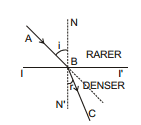
When light moves from denser to rarer medium it bends away from normal.

When light moves from rarer to denser medium it bends towards the normal.
Ex.35 A light ray is incident on a glass sphere at an angle of incidence 60° as shown. Find the angles r, r´, e and the total deviation after two refractions.

Sol. Applying Snell's law 1 sin 60° =  ⇒ r = 30°
From symmetry r' = r = 30°
Again applying snell's law at second surface
1 sin e =  ⇒ e = 60°
Deviation at first surface = i- r = 60°- 30° = 30°
Deviation at second surface
= e- r´ = 60°- 30° = 30°
Therefore total deviation = 60°
Ex.36 Find the angle qa made by the light ray when it gets refracted from water to air, as shown in figure.
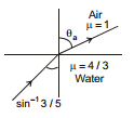
Sol. Snell's Law

Ex.37 Find the speed of light in medium 'a' if speed of light in medium 'b' is  where c =speed of light in vacuum and light refracts from medium 'a' to medium 'b' making 45° and 60° respectively with the normal.
Sol. Snell's Law

13.2 Plane Refraction :

Prove that n1 sin i1 = n2 sin i2 = n3 sin i3 = n4 sin i4
= (Remember this). Also Prove that if n1 = n4 then light rays in medium n1 and in medium n4 are parallel.
14. APPARENT DEPTH AND NORMAL SHIFT
Case I : When the object is in denser medium and the observer is in rarer medium (near normal incidence)
When an object O is in denser medium of depth 'd' and absolute refractive index n1and is viewed almost normally to the surface from the outside rarer medium (r.i = n2), its image is seen at I. which is at a distance d´ from surface AO is the real depth of the object. AI is the apparent depth of the object. Ol is called apparent shift.
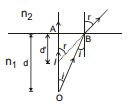
According to Snell's law, 
or,  (Q i and r are small angles)
 =
= 

 : 1. The above formula is value only for paraxial rays.
2. distances should be taken from surface
3. n2 is the reflective index of the medium, where ray is going and n1 from where ray is coming
Ex.38 Find out the following in the figure shown below :
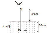
(a) The apparent distance of the fish from the surface as observed by the bird
(b) The apparent distance of the bird from the surface as observed by the fish
Sol. (a) 
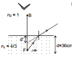
 ⇒ d´ = 27 cm
(b) 
 ⇒ d´ = 48 cm
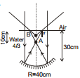
Ex.39 A concave mirror is placed inside water with its shining surface upwards and principal axis vertical as shown. Rays are incident parallel to the principal axis of concave mirror. Find the position of final image.

Sol. The incident rays will pass undeviated through the water surface and strike the mirror parallel to its principal axis. Therefore for the mirror, object is at ∞. Its image A (in figure) will be formed at focus which is 20 cm from the mirror. Now for the interface between water and air, d = 10 cm
Therefore, 
14.1 Velocity of the image in case of plane refraction :
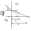
 ⇒
⇒ 
 ⇒
⇒ 
Ex.40 Find out the following in the figure shown below :
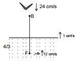
(a) The apparent speed of the fish as observed by the bird
(b) The apparent speed of the bird as observed by the fish
Sol. (a)  ⇒
⇒ 
 + 1 =
+ 1 = 
(b) n2 = 4/3, n1 = 1

v0 =- 24, vs = + 1
⇒ vI - 1 =  [- 24- 1]
vI =  ⇒ vI f =
  =
=  cm/sec.
15. REFRACTION THROUGH A GLASS SLAB
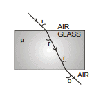
When a light ray passes through a glass slab having parallel faces, it gets refracted twice before finally emerging out of it.
First refraction takes place from air to glass.
So, m =  ...(i)
The second refraction takes place from glass to air.
So,  ...(ii)
From equations (i) and (ii), we get
 ⇒ i = e
Thus, the emergent ray is parallel to the incident ray.
15.1 Apparent shift due to slab when object is seen normally through the slab

Ist Refraction
Because of the refraction at the first surface, the image of O is formed at I1. For this refraction, the real depth is x and the apparent depth is d´. Also, the first medium is air and the second is the slab. Thus,
 ⇒ mx
⇒ mx
IInd Refraction
The point I1 acts as the object for the refraction at the second surface. Due to this refraction, the image of I1 is formed at I2. Thus.
 ⇒
⇒ 
Shift S = x + t- x- 
S = 
If medium is not air outside the slab
S = 
Important points
1. Rays should be paraxial
2. Medium on both side of the slab should be same.
3. Shift comes out from the object
4. Shift is independent of the distance of the object from the slab.
5. If shift comes out +ve then shift is towards the direction of incident rays and vice versa.
Ex.41 Calculate the shift produced by the slab having thickness 15cm and refractive index 1.5 which is kept in air.
Sol. shift S =  =
=  = 5 cm
Ex.42 See the figure. Find the distance of final image formed by mirror
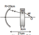
Sol. Shift =  =
= 
For mirror object is at a distance
= 21-  = 20 cm
Therefore, Object is at the centre of curvature of mirror. Hence the light ray will retrace and image will formed on the object itself.
Ex.43 Findout the distance between image and the mirror as observed by observer in the figure shown below

Sol.

shift = 
u =- 40, f = + 40
v = + 20 cm
the distance between mirror and the image as observed by observer = 20- shift = 15 cm
15.2 Apparent distance between object and observer when both are in different medium.

Ist Refraction : 

IInd Refraction :
 =
= 
Final distance of image from observer = 

 If object and observer are in same medium then shift formula should be used and if both are in different medium then the above formula of apparent distance should be used.
15.3 LATERAL SHIFT
The perpendicular distance between the incident ray and the emergent ray, when the light is incident obliquely on a parallel sided refracting glass slab is called 'lateral shift'.
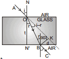
In right - angled triangle OBK, we have
 = i- r
Therefore, sin (i- r) = 
or, d = OB sin (i- r) ...(i)
In right angled triangle ON´ B, we have
cos r =  or, OB =
Substituting the above value of OB in equation (i), we get
d =  ...(13)
Ex.44 Find the lateral shift of light ray while is passes through a parallel glass slab of thickness 10 cm placed in air. The angle of incidence in air is 60° and the angle of refraction in glass is 45°.
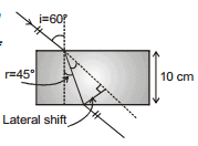
Sol. d =  =
= 
=  =
= 
16. Critical Angle and Total Internal Reflection (T.I.R.)
Critical angle is the angle made in denser medium for which the angle of refraction in rarer medium is 90°. When angle in denser medium is more then critical angle the light ray reflects back in denser medium following the laws of reflection and the interface behaves like a perfectly reflecting mirror. In the figure.
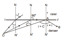
O = object
NN´ = Normal to the interface
II´ = Interface
C = Critical angle :
AB = reflected ray due to T.I.R.
When i = C then r = 90°
Therefore, 
16.1 Conditions of T.I.R. :
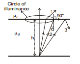
(a) light is incident on the interface from denser medium.
(b) Angle of incidence should be greater than the critical angle (i > c). Figure shows a luminous object placed in denser medium at a distance h from an interface separating two media of refractive indices mr and md.Subscript r & d stand for rarer and denser medium respectively.
In the figure ray 1 strikes the surface at an angle less than critical angle C and gets refracted in rarer medium. Ray 2 strikes the surface at critical angle and grazes the interface. Ray 3 strikes the surface making an angle more than critical angle and gets internally reflected. The locus of points where ray strikes at critical angle is a circle, called circle of illuminance. All light rays striking inside the circle of illuminance get refracted in rarer medium. If an observer is in rarer medium, he/she will see light coming out only from within the circle of illuminance. If a circular opaque plate covers the circle of illuminance, no light will get refracted in rarer medium and then the object can not be seen from the rarer medium. Radius of C.O.I can be easily found.
Ex.45 Find the max. angle that can be made in glass medium (m = 1.5) if a light ray is refracted from glass to vacuum.
Sol. 1.5 sin C = 1 sin 90°, where C = critical angle.
sin C = 2/3 ⇒ C = sin-12/3
Ex.46 Find the angle of refraction in a medium (n = 2) if light is incident in vacuum, making angle equal to twice the critical angle.
Sol. Since the incident light is in rarer medium. Total Internal Reflection can not take place.
C =  = 30° ⇒ Therefore, i = 2C = 60°
Applying Snell's Law. 1 sin 60° = 2 sin r
 ⇒
⇒ 
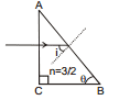
Ex.47 What should be the value of angle q so that light entering normally through the surface AC of a prism (n = 3/2) does not cross the second refracting surface AB.

Sol. Light ray will pass the surface AC without bending since it is incident normally. Suppose it strikes the surface AB at an angle of incidence i.
i = 90°- θ
For the required condition :
90°- θ > C
or sin (90°- θ) > sin C
or cos θ > sin C =  =
= 
or θ < cos-1
Ex.48 A ray of light from a denser medium strikes a rarer medium at an angle of incidence i. if the reflected and the refracted rays are mutually perpendicular to each other, what is the value of the critical angle?
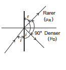
Sol. From Snell's law, we have
 or, m =
  ...(i)
According to the given problem,
i + r + 90° = 180° or, r = 90°- i
Substituting the above value of 'r' in equation (i), we get
μ =  or, μ = cot i ...(ii)
By definition C = 
or, C =  (using equation(ii) or,
16.2 Optical fibre cable :

Find out the range of n for which ray will show T.I.R through curved surface.
Sol. It is required that all possible r´ should be more than critical angle. This will be automatically fulfilled if minimum r´ is more than critical angle
Angle r´ is minimum when r is maximum i.e. C (Why ?). Therefore the minimum value of r' is 90°- C.
For T.I.R.
(90- r)min > C
90- rmax > C
for rmax ⇒ imax = 90°
when i = 90°, r = C
90°- C > C ⇒ C < 45°
⇒ sin C < sin 45°
⇒  ⇒
⇒ 
Graph between  :
:

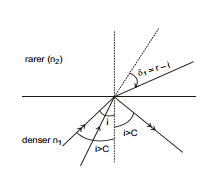

and n1 sin i = n2 sin r

so  ...(1)
when i > C :
then  ...(2)

Note : If the  is between
  , then there are 2 possible values of i.
Variable Refractive Index :
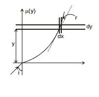
If R.I. is a function of y :
taking an small element of y of width dy
here 
Now 1 sin i = μ (y). sin r
tanθ =  = tan (90°- r)
or cot r = 
so 
⇒  =
= 

17. Prism
A homogeneous solid transparent and refracting medium bounded by two plane surfaces inclined at an angle is called a prism :
3-D View


Refraction through a prism :

(a) PQ and PR are refracting surfaces.
(b) = A is called refracting angle or the angle of prism (also called Apex angle.)
(c) 
(d) For refraction of a monochromatic (single wave length) ray of light through a prism;
 and r1 + r2 = A
Therefore, 
Note I. If ray crosses two surface which are inclined to each other then we use the concept of prism
II. If ray crosses two plain parallel surfaces then we use concept of slab.
Ex.49 A ray of light is incident on one face of a prism (μ = 1.5) at an angle of 60°. The refracting angle of the prism is also 60°. Find the angle of emergence and the angle of deviation. Is there any other angle of incidence, which will produce the same deviation?
Sol. Angle of incidence = i = 60°
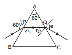
At point P,  ⇒ sin r1 =
or, r1 is not equal to 35°6´
Using r1 + r2 = A, we get
r2 = A- r1 = 60°- 35°6´ = 24°44´
At point Q, 
⇒ sin e = 1.5 sin 24° 44´ ⇒ sin e = 0.63
⇒ e = 39°
Therefore, deviation =  - A = 60° + 39°- 60° = 39°
If i and e are interchanged, deviation remains the same. Hence same deviation is obtained for angles of incidence 60° and 39°.
Ex.50 A ray of light makes an angle of 60° on one of the faces of a prism and suffers a total deviation of 30° on emergence from the other face. If the anlge of the prism is 30°, show that the emergent ray is perpendicular to the other face. Also calculate the refractive index of the material of the prism.
Sol. The angle of deviation 
Here,  , i1 = 60°; A = 30°
Hence 30° = 60° + i2 - 30° = 30° + i2
⇒ i2 = 0
The angle of emergence is zero. This means that the emergent ray is perpendicular to the second face.
Since i2 = 0, the anlge of incidence at the second face is zero.
Therefore, r2 = 0
Now, r1 + r2 = A
or, r1 = A = 30°
We know, μ =  =
=  =
= 
 = 1.732
17.1 Graph between 

(1) Variation of  (shown in diagram).
For one  there are two values of angle of incidence. If i and e are interchanged then we get the same
  because of reversibility principle of light
(2) There is one and only one angle of incidence for which the angle of deviation is minimum.
(3) Right hand side part of the graph is more tilted then the left hand side.
17.2 Minimum Deviation and Condition for Minimum Deviation :
The angle of deviation depends on the anlge of incidence in a particular way. When the angle of incidence is small, the deviation is large. As i increase, d decreases rapidly and attains a minimum value and then increases slowly with increase of i. The minimum value of d so attained is called the minimum deviation  .
.


Condition
Theory and experiment shows  will be minimum when the path of the light ray through the prism is symmetrical.
i.e., angle of incidence = angle of emergence
or, 
For the refraction at the face AB, we have
 or, sin i = μ sin r1,
and,  or, sin e = μ sin r2
Therefore, m sin r1 = μ sin r2
or, r1 = r2
Hence, the condition for minimum deviation is
i = e and r1 = r2 ....(19)
17.3 Relation Between Refractive index and the angle of Minimum Deviation
When  we have
e = i and r1 = r2 = r (say)
We know
A = r1 + r2 = r + r = 2r or, r =
Also,
or, 
The refractive index of the material of the prism is given by
 or, μ =
  ...(20)
If surrounding medium has refractive index = ns
then  =
= 
Ex.51 A ray of light incident at 49° on the face of an equilateral prism passes symmetrically Calculate the refractive index of the material of the prism.
Sol. As the prism is an equilateral one, A = 60°. As the ray of light passes symmetrically, the prism is in the position of minimum deviation.
So, r =  =
=  = 30°
= 30°
also, i = 49°
Therefore, μ =  =
=  =
=  = 1.5
= 1.5
Ex.52 The refracting angle of the prism is 60° and the refractive index of the material of the prism is 1.632. Calculate the angle of minimum deviation.
Sol. Here, A = 60° ; μ = 1.632
Now, 
or, 
or,  = 1.632 × sin 30° = 1.632 × 0.5
or,  = 0.816 or,

17.4 Condition for prism :
(a) Relation between prism angle A & critical angle C such that ray will always show T I R at BC :
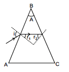
For this (r2)min > C ...(i)
For (r2)min, r1 should be maximum and
for (r1)max ⇒ imax = 90°


Now from eq. (i) A- C > C
A > 2C
i.e. A > 2C, all rays are reflected back from the second surface.
(b) The relation between A & C such that ray will always cross surface BC.
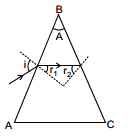
For this (r2)max < C
(A- r1)max < C
A- (r1)min < C ..(2)
(r1)min = 0 when imin = 0
from eq. (2) A- 0 < C
A < C
i.e. If A £ C, no rays are reflected back from the second surface i.e. all rays are refracted from second surface.
(c) If 2C ³ A > C, some rays are reflected back from the second surface and some rays are refracted from second surface, depending on the angle of incidence.


⇒ imin (corresponding to e = 90º) and i = 90º
(corresponding to emin).
For imin : ns sin imin = np sin (A- C)
If i < imin then T.I.R. takes place at second refracting surface PR.

i = 90° or e = 90°


n sin (A- C) = sin e

e = 


Ex.53 Find the minimum and maximum angle of deviation for a prism with angle A = 60° and μ = 1.5
Sol. Minimum deviation
The angle of minimum deviation occurs when i = e and r1 = r2 and is given by
 ⇒
⇒  =
= 
Substituting μ = 1.5 and A = 60°, we get
 = 2 sin-1 (0.75)- 60° = 37°
Maximum deviation (Grazing incidence or Grazing emergence) :
The deviation is maximum when i = 90° or e = 90° that is at grazing incidence or grazing emergence.
Let i = 90°
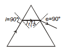
⇒ r1 = C =  ⇒ r1 =
⇒ r2 = A- r1 = 60°- 42° = 18°
Using  , we have
sin e = μ sin r2 = 1.5 × sin 18°
⇒ sin e = 0.463 ⇒ e = 28°
Therefore, Deviation = = (i + e)- A
= 90° + 28°- 60° = 58°
17.5 Deviation Through a Prism of Small Angle
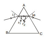
If the angle of the prism A is small, r1 and r2
(as r1 + r2 = A) and i and e will be small.
For the refraction at the face AB, we have μ=
or, μ =  (since i and r1 are small angles, sin i1 is not equal to i1 and sin r1 is not equal to r1 )
⇒ For refraction at the face AC, we have
μ =  or, μ =
  (Q e and r2 are small angles, so sin e
  e and sin r2
  r2)
r2)
⇒ e = mr2
Now, deviation produced by a prism

The above formula is valid for all positions of the prism provided the angle of the prism A is small 
Ex.54 A prism having a refracting angle 4° and refractive index 1.5 is located in front of a vertical plane mirror as shown. A horizontal ray of light is incident on the prism. What is the angle of incidence at the mirror?

Sol. The deviation suffered by refraction through the small angled prism is given by

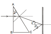
This gives the angle of incidence 2° at the mirror.
Ex.55 Refracting angle of a prism A = 60º and its refractive index is, n = 3/2, what is the angle of incidence i to get minimum deviation. Also find the minimum deviation. Assume the surrounding medium to be air (n = 1).
Sol. For minimum deviation,
r1 = r2 =  = 30º
= 30º
Applying snell's law at I surface
1 × sin i =  sin 30º ⇒
  ⇒
⇒
Ex.56 For a prism, A = 60º,  . Find the minimum possible angle of incidence, so that the light ray is refracted from the second surface. Also find
  .
.
Sol. In minimum incidence case the angles will be as shown in figure
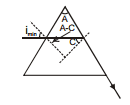
Applying snell's law :
1 × sin  sin (A- C)
 (sin A cos C- cos A sin C)

Therefore, imin = 30º
Therefore,  = imin + 90º- A = 30º + 90º- 60º = 60º.
18. Dispersion of Light
The angular splitting of a ray of white light into a number of components and spreading in different directions is called Dispersion of Light. [It is for whole Electro Magnetic Wave in totality]. This phenomenon takes place because waves of different wavelength move with same speed in vacuum but with different speeds in a medium.
Therefore, the refractive index of a medium depends slightly on wavelength also. This variation of refractive index with wavelength is given by Cauchy's formula.
Cauchy's formula n(l) = a + 
where a and b are positive constants of a medium.

Note :
Such phenomenon is not exhibited by sound waves.
Angle between the rays of the extreme colour in the refracted (dispersed) light is called angle of dispersion
θ = dv - dr (Fig. (a))
Fig (a) and (c) represents dispersion, whereas in fig. (b) there is no dispersion.


For prism of small 'A' and with small 'i'.

Ex.57 The refractive indices of flint glass for red and violet light are 1.613 and 1.632 respectively. Find the angular dispersion produced by a thin prism of flint glass having refracting angle 5°.
Sol. Deviation of the red light is  and deviation of the violet light is
The dispersion =
= (1.632- 1.613) × 5° = 0.095°
Note : Deviation of beam (also called mean deviation)

nv, nr and ny are R.I. of material for violet, red and yellow colours respectively.
Numerical data reveals that if the average value of μ is small μv - μr is also small and if the average value of μ is large μv - μr is also large. Thus, larger the mean deviation, larger will be the angular dispersion.
18.1 Dispersive power (ω) of the medium of the material of prism is given by :

ω is the property of a medium.
For small angled prism  with light incident at small angle i :
 =
=  =
=  =
= 
[ny =  if ny is not given in the problem]
n- 1 = refractivity of the medium for the corresponding colour.
Ex.58 Refractive index of glass for red and violet colours are 1.50 and 1.60 respectively. Find
(a) the refractive index for yellow colour, approximately
(b) Dispersive power of the medium.
Sol. (a)  =
=  = 1.55
(b)  =
=  = 0.18.
Ex.59 Calculate the dispersive power of crown and flint glass-prism from the following data. For crown glass
μv = 1.522 ; μR = 1.514
For flint glass
μv = 1.662 ; μR = 1.644
Sol. For crown glass
μv = 1.522 ; μR : 1.514
Therefore, μY =  =
=  = 1.518
Hence, the dispersive power of crown glass
ω=  =
=  = 0.01544
Therefore, ω= 0.01544
For flint glass : μ´v = 1.662 ; μ´R = 1.644
Therefore,  =
=  = 1.653
Therefore,  =
=  = 0.0276
18.2 Dispersion without average deviation and average deviation without dispersion

Figure shows two thin prisms placed in contact in such a way that the two refracting angles are reversed with respect to each other. Suppose, the refracting angles of the two prisms are A and A´ and their dispersive power and ω and ω´ respectively.
Consider a ray of light for which the refractive indices of the materials of the two prisms are μ and μ´. Assuming that the ray passes through the prisms in symmetrical situation, the deviations produceed by the two prisms are

and 
As the two deviations are opposite to each other, the net deviation is

 ...(1)
If white light passes through the combination, the net deviation of the violet ray is

and that of the red ray is

The angular dispersion produced by the combination is
 ...(2)
The dispersive power are given by
 and
and 
Thus, by (2), the net angular dispersion is
 ...(3)
The net deviation of the yellow ray i.e., the average deviation, is, by (1)
 ...(4)
Dispersion without Average Deviation
If the combination is not to produce a net average deviation in the beam, dy should by 0. By (4), the required condition is
 ...(5)
Using this in (3), the net angular dispersion produced is
 ...(6)
By choosing ω and ω´ different and the refracting angles to satisfy (5), one can get dispersion without average deviation.
Average Deviation without Dispersion.
If the combination is not to produe a net dispersion,  , By (iii)
 ....(7)
By (2), this condition may also be written as
 ....(8)
The net average deviation produced is, by (1),


By (7)

so that the net average deviation produced by the combination is
 ...(9)
Ex.60 Find the angle of the flint glass prism which should be combined with a crown glass prism of 5° so as to give dispersion but no deviation.
For crown glass : μv = 1.523; μR = 1.515
For flint glass : μv´ = 1.688 ; μR´ = 1.650
Sol. For no deviation
 or,
or, 
Now, μ =  =
=  = 1.519
 Therefore,
  = 3.94°
Ex.61 Find the angle of a prims of dispersive power 0.021 and refractive index 1.53 to form an achromatic combination with the prism of angle 4.2° and dispersive power 0.045 having refractive index 1.65. Also calculate the resultant deviation.
Sol. ω = 0.021 ; μ = 1.53 ; ω´ = 0.045; μ´ = 1.65
A´ = 4.2°
For no dispersion

or, 
or, 
Net deviation d + d´ = (m- 1) A + (m´- 1) A´
=- 11.04° (1.53- 1) + 4.2° (1.65- 1) =- 3.12°
19. Refraction from a Spherical Surface
Consider two transparent media having indices of refraction μ1 and μ2, where the boundary between the two media is a spherical surface of radius R. We assume that μ1 < μ2. Let us consider a single ray leaving point O and focussing at point I. Snell's law applied to this refracted ray gives,
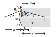
μ1 sin q1 = μ2 sin q2
Because θ1 and θ2 are assumed to be small,
we can use the small angle approximation
sin θ is not equal to θ
(angles in radians) and say that
μ1 θ1 = μ2 θ2 ...(1)
From the geometry shown in the figure.
θ1 = α + β ...(2)
and β = θ2 + γ ...(3)
Eqs. (1) and (3) can be combined to express θ2 in terms of α and β. Substituting the resulting expression into Eq. (2) then yields.
β = 
So  ...(4)
Since, the arc PM (of length S) subtends an angle β at the centre of curvature
β = 
Also in the paraxial approxiamation
α =  and γ =
Using these expressions in Eq. (4) with proper signs, we are left with,

or  ...(5)
Although the formula (5) is derived for a particular situation, it is valid for all other situations of refraction at a single spherical surface.
Important point for above formula
Above formula is valid only for paraxial ray.
u,v,R should be put along with sign
μ2 is r.i. of medium in which rays is going and μ1 is the r.i. of medium from which rays are coming.
Ex.62 Findout the position of the image formed and draw the appropriate ray diagram
u =- 30 cm
R = + 10 cm

Sol. ⇒ 
⇒ 
⇒ 

 ⇒ v =
⇒ v =  = 90 cm (Real)
Ex.63 Findout the position of the image formed and draw the appropriate ray diagram

Sol. n2 = 1.5, n1 = 1
u =- 5cm R =- 10 cm

⇒  ⇒
⇒ 

⇒  ⇒ v =- 6 cm
Ex.64 Findout the position where parallel rays will meet after coming out of the sphere and draw the appropriate ray diagram
Sol. 
⇒  ⇒
⇒ 
⇒ v = 
For IInd
 =
=  ⇒ v = + 5

19.1 Velocity of spherical refrection

differentiate with respect to time


Ex.65 Find the velocity of image in the shown below

⇒  ⇒
⇒ 
⇒ v =  = 90 cm

By differentiating :

⇒ 
⇒  = + 12 m/sec
19.2 Transverse Magnification
If i and r are very small
tan i is not equal to sin i is not equal to i
tan r is not equal to sin r is not equal to r
⇒ tan r =  ⇒ r is not equal to
  ...(1)
tan i =  ⇒ i is not equal to
  ...(2)
Again, by applying snells law :
n1 sin i = n2 sin r
⇒ n1 i is not equal to n2 r ...(3)
⇒ From (1), (2), (3)
m = 
Ex.66 Findout the position of the image formed and draw the appropriate ray diagram.

u =-30 cm
R = + 10 cm
Sol. 
⇒  =
= 
⇒ 

⇒ 
⇒ v = + 90
Mirror will form the image of I1 30 cm behind it as shown in the figure.
For the second refraction :
u =- 150 cm, R =- 10 cm, n1 = 1.5, n2 = 1
 ⇒
⇒ 
⇒  ⇒ v = 25 cm (Real)
Ex.67 Find out the value of x for which the image is formed on the object itself.

Sol. Case I : for first Refraction
 =
= 
⇒  =
=  ⇒
⇒ 

⇒  ⇒
⇒ 
v = ∞ ⇒ x = 20 cm
case II :
n2 = 1.5, n1 = 1
R = + 10, u =- x 
v = 90 cm, x = 30 cm
20. REFRACTION THROUGH THIN LENSES
Lens : A lens is a transparent medium bounded by two refracting surfaces such that at least one of the refracting surfaces is curved. (or spherical)
Types of lenses. : Broadly, lenses are of the following types :


(ii) Principal axis : The line joining the centres of curvature of the two bounding surfaces is called the principal axis.

20.1 Lens Maker formula
For first refraction :

 =
=  ...(1) thickness of lens t is negligible
For second refraction :
 ...(2)
Adding (1) and (2) equation we get

Impoartant points for the above formula :
(1) Rays should be paraxial
(2) v, u, R1 and R2 should be put with the sign.
(3) R1 is the radius of curvature of that surface on which the ray strikes first.
(4) Lens should be thin.
(5) Medium on both sides of the lens should be same.
20.2 Sign Convention (consider pole as origin)
(i) Whenever and wherever possible, rays of light are taken to travel from left to right.
(ii) Distances are measured along the principal axis from the optical centre of the lens.
(iii) Distances measured along the principal axis in the direction of the incident rays are taken as positive while those measured against the direction of the incident rays are taken negative.
(iv) Distances measured above the principal axis are taken as positive and those measured below the principal axis are taken as negative.


20.3 Focus :
If the rays are parallel to optical axis and paraxial then the point where they meet or appears to meet is known as focus of the system.
In the lens maker formula if u →∞, v = f.


Substituting in the lens maker formula :
 (lens formula)
Lenses have two focii called first and second focus

Ex.68 Calculate the focal length of a biconvex lens in air if the radii of its surfaces are 60 cm and 15 cm. Refractive index of glass = 1.5
Sol. Consider a light ray going through the lens as shown. It strikes the convex side of 60 cm radius and concave side of 15 cm radius while coming out.


- Since for converging and diverging lenses
- Focal length of lens depends on surrounding medium.
- If f = + ve implies converging and if f = - ve implies diverging lens.

Ex.69 Calculate the focal length of the lens shown in the figure.

Sol.

⇒ f = 120 cm
If in the above case direction of rays is reversed.


f = + 120 cm
This Illustration shows that focal length does not depend on the incident ray direction.
20.4 RULES FOR IMAGE FORMATION
(i) A ray passing through the optical centre of the lens proceeds undeviated through the lens. (By definition of optical centre)

Pole is the intersection of the ray which goes undeviated through the lens and the optical axis.
(ii) A ray passing parallel to the principal axis after refraction through the lens passes or appear to pass through the focus. (By the definition of the focus)

(iii) A ray through the focus or directed towards the focus, after refraction from the lens, becomes parallel to the principal axis. (Principle of reversibility of light)

Only two rays from the same point of an object are needed for image formation and the point where the rays after refraction through the lens intersect or appear to intersect, is the image of the object. If they actually intersect each other, the image is real and if they appear to intersect the image is said to be virtual.
Ex.70 Findout the position of the image formed.
u = + 30 cm, f = + 10 cm
Sol.  20.5 Transverse Magnification
Converging lens.

Ex.71 Findout the position, height and nature of the image formed.

Therefore, Real, inverted, diminished
21. IMAGE FORMATION BY A CONVEX LENS OF THE LINEAR OBJECT
(i) When the object is at infinity :
 The image is formed at F. It is real, inverted and highly diminished.
(ii) When the object is beyond 2F :

The image is formed between F and 2F. It is real, inverted and diminished
(iii) When the object is at 2F :

The image is formed at 2F. It is real, inverted and the same size as the object.
(iv) When the object is between F and 2F :

The image is formed beyond 2F (i.e., between 2F and →). It is real, inverted and enlarged.
(v) When the object is at F :

The image is formed at infinity. It is real, inverted and highly magnified.
(vi) When the object is between F and O :

The image is on the same side as the object is. It is virtual, erect and magnified.

Graphs for converging lens

21.1 IMAGE FORMATION BY A CONCAVE LENS OF A LINEAR OBJECT
(a) Real object case

Graphs for diverging lenses.
 Ex.72 An object is placed in front of a converging lens of focal length 10 cm and image formed is double the size of object. Then find out the position of object.
Case I : If the image formed is real

Ex.73 Findout the linear length of the image of the object AB shown in figure.


Ex.74 Findout the linear length of the image of the object shown in figure.

Note : Differentiating in solving 73 & 74 (Trick)
21.2 Velocity of the image formed by a lens


FAQs on GEOMETRICAL OPTICS, Class 12, Physics (IIT-JEE & AIPMT) Chapter Notes
| 1. What is geometrical optics? |  |
| 2. What is the difference between reflection and refraction in geometrical optics? |  |
| 3. What is the principle of least time in geometrical optics? |  |
| 4. What is the difference between a real and a virtual image in geometrical optics? |  |
| 5. What are the applications of geometrical optics? |  |

|
Explore Courses for Class 12 exam
|

|


