Design For Static Loading - 1


Introduction
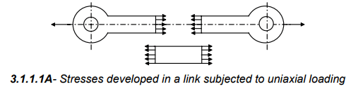
Machine parts fail when the internal stresses produced by external forces exceed the material strength. External loads produce internal stresses in elements; the required component size is determined from these stresses. Stresses developed in a link subjected to uniaxial loading are illustrated in figure-3.1.1.1. Loading on machine elements may arise from several sources:
- The energy transmitted by a machine element.
- Dead weight of the part or assembly.
- Inertial forces due to acceleration or deceleration.
- Thermal loading from temperature gradients or expansion.
- Frictional forces between contact surfaces.
Classification of loading - static and dynamic
Load may also be classified in terms of its variation with time and direction. Two basic categories are:
- Static load - the load does not change significantly in magnitude or direction and usually increases gradually to a steady value.
- Dynamic load - the load varies in magnitude and/or direction with time. Examples are varying traffic loads on a bridge and alternating pressure on a double-acting piston.
Vibration and shock are special types of dynamic loading. Figure-3.1.1.2 shows typical load versus time characteristics for static and dynamic loading of machine elements.
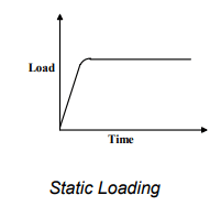
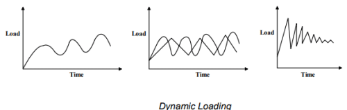
3.1.1.2F - Types of loading on machine elements.
Allowable Stresses and Factor of Safety
Determination of stresses in structural or machine components is useful only when compared to the material strength. If the induced stress is less than or equal to an adopted limiting material strength value, the component can be considered safe and its size can be estimated. Material strengths are determined in laboratory tests on standard specimens. For tension and compression tests a round rod of specified dimensions is loaded in a tensile test machine until fracture. The final load at fracture is the ultimate load, and the ratio of this load to the original cross-sectional area is the ultimate stress.
Similar standard tests are available for bending, shear and torsion; handbook data summarise these results for common engineering materials. In design practice an allowable stress (also called permissible stress) is used instead of the measured critical stress to allow for various uncertainties. Sources of uncertainty and causes for reducing the working stress include:
- Uncertainty in the magnitude and nature of applied loading.
- Material inhomogeneity and scatter of material properties.
- Material behaviours such as corrosion, plastic flow and creep.
- Residual stresses produced by manufacturing processes.
- Fluctuating loads (fatigue) - experimental S-N curves show ultimate strength depends on the number of cycles.
- Required safety and reliability levels for the application.
For ductile materials the yield strength is usually taken as the critical stress for design; for brittle materials the ultimate (or tensile) strength is used. The allowable stress is set well below these critical strengths. The factor of safety (n) is defined as the ratio of strength to allowable stress as shown in the following relation:
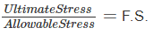
The factor of safety must always be greater than unity. It is common to express the ratio in terms of stresses so that the same relation applies irrespective of whether the limiting strength is ultimate or yield.
Theories of Failure
When a machine element experiences a complex system of stresses (multi-axial stress state), an appropriate failure criterion is needed to predict the mode of failure. Theories of failure provide design-ready criteria to decide whether a component will fail under the specified loading. In machine design a part is considered to have failed when it no longer performs its intended function. There are two primary mechanical failure modes:
- Yielding - excessive inelastic (permanent) deformation that renders the part unfit for service; common in ductile materials.
- Fracture - the component separates into two or more parts; common in brittle materials.
There is no sharp boundary between ductile and brittle behaviour. As a practical guideline, materials with percentage elongation less than about 5% are often treated as brittle, and those with elongation greater than 15% are treated as ductile. However, ductile materials may fail by fracture under certain conditions such as:
- Cyclic (fatigue) loading.
- Long-term static loading at elevated temperature (creep leading to eventual fracture).
- Impact or shock loading.
- Work hardening causing embrittlement.
- Severe quenching producing brittle microstructures.
Appropriate failure theories are chosen depending on whether yielding or fracture is the governing failure mode and on the state of stress (tension, compression, shear, torsion, or combined). Common criteria used in practice include the maximum normal stress theory, maximum shear stress theory (Tresca), and the distortion energy theory (von Mises). Selection depends on material ductility and nature of the stress state.
Stress-Strain Behaviour and Typical Diagrams
The stress-strain response of a material under tensile loading illustrates the difference between yielding and fracture behaviours. A typical engineering stress-strain curve for a ductile material (for example, low-carbon steel) is shown in figure-3.1.3.1 (a). A number of important points appear on this diagram:
- Proportional limit - up to this point stress is proportional to strain and Hooke's law applies.
- Yield point (σy) - material begins to deform plastically; beyond this point permanent deformation remains when load is removed.
- Ultimate tensile stress (σu) - the peak engineering stress the specimen reaches.
- Necking and fracture - after the ultimate stress the specimen undergoes local reduction in area (necking) and finally fractures.
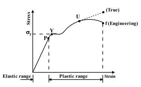
3.1.3.1F - (a) Stress-strain diagram for a ductile material e.g. low-carbon steel.
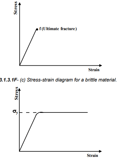
3.1.3.1F - (d) Stress-strain diagram for an elastic-perfectly plastic material.
For an elastic-perfectly plastic material, yielding continues at essentially constant stress beyond the yield point; the engineering stress-strain curve is nearly parallel to the strain axis after yield. For most real ductile materials the stress rises beyond yield until it reaches the ultimate tensile stress σu, beyond which the engineering stress falls because the original cross-sectional area is used in the stress calculation even though the instantaneous area decreases during necking. If instantaneous area were used, the true stress curve would continue to rise until fracture.
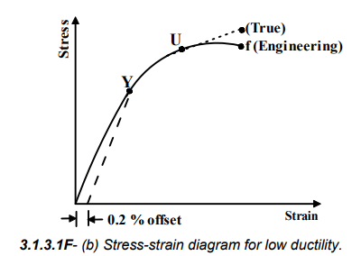
For brittle materials the stress-strain curve is essentially linear up to fracture with little or no plastic deformation. When a material has no distinct yield point, a convenient offset yield (for example 0.2% proof stress) is defined for design reference.
Design for Static Loading - Practical Procedure
A typical design procedure for a component under static (steady) loading is:
- Identify the maximum external loads and load directions.
- Determine the internal stress or the governing stress formula for the component geometry and loading (axial stress, bending stress, shear stress, torsional shear stress, or combined stresses).
- Select an appropriate failure criterion and the relevant material strength (yield or ultimate) based on material behaviour and service conditions.
- Choose a suitable factor of safety and compute the allowable stress = material strength / factor of safety.
- Size the component so that the calculated working stresses do not exceed allowable stresses. Provide details for manufacturing, surface finish, fit, residual stresses and corrosion protection as required.
Simple worked example (axial member)
Design the diameter of a solid circular rod carrying an axial tensile static load P = 20 kN if allowable tensile stress is 80 MPa. Use the usual relation between tensile stress and area.
Sol.
Calculate required cross-sectional area A from σ = P / A.
A = P ÷ σ
A = 20 000 N ÷ 80 000 N·m⁻²
A = 0.25 × 10⁻³ m² = 250 mm²
For a circular section A = πd² / 4; solve for d.
d² = 4A ÷ π
d² = 4 × 250 mm² ÷ π
d² = 1000 ÷ π mm²
d = √(1000 ÷ π) mm
d ≈ 17.84 mm
Choose a convenient standard diameter greater than computed value; for example, d = 18 mm or d = 20 mm depending on manufacturing and fit considerations.
Applications and Design Considerations
Design for static loading is the foundation for many machine elements and structures where loads are steady or change slowly. Typical applications include columns, struts, shafts subject to constant torque, unshocked pressure vessels under internal pressure (if no cyclic loading), and structural members carrying steady loads.
Practical points for safe static design include:
- Selecting a conservative factor of safety appropriate for the consequence of failure and the reliability required.
- Accounting for stress concentrations due to holes, fillets, keyways and notches by using stress concentration factors or improving geometry.
- Considering manufacturing effects and surface finish since these affect fatigue even if primary load is static.
- Specifying corrosion protection or material selection for the service environment.
- Verifying that secondary effects (thermal stresses, residual stresses) do not reduce the effective allowable stress below the design assumption.
Summary
Design for static loading requires identification of loads, calculation of induced stresses, selection of appropriate material strength (yield or ultimate), adoption of a factor of safety, and selection of dimensions so that working stresses remain below allowable values. Understanding stress-strain behaviour, failure modes (yielding and fracture) and proper application of failure theories are essential for safe and economical machine-element design.
FAQs on Design For Static Loading - 1
| 1. What is static loading in mechanical engineering? |  |
| 2. What are the key considerations in the design for static loading? | |
| 3. How can I calculate the maximum load a structure can withstand under static loading? | |
| 4. What are the common failure modes in static loading? | |
| 5. How can I ensure the reliability and safety of a structure under static loading? | |


