Design and Construction of Concrete Gravity Dams (Part -7)

Introduction
An embankment dam, as defined earlier, is one that is built of natural materials. In its simplest and oldest form, the embankment dam was constructed with low-permeability soils to a nominally homogeneous profile. The section featured neither internal drainage nor a cutoff to restrict seepage flow through the foundation. Dams of this type proved vulnerable associated with uncontrolled seepage, but there was little progress in design prior to the nineteenth century. It was then increasingly recognized that, in principle, larger embankment dams required two component elements.
- An impervious water-retaining element or core of very low permeability of soil, for example, soft clay or a heavily remoulded 'puddle' clay, and
- Supporting shoulders of coarser earthfill(or of rockfill), to provide structural stability
As a further enhancement to the design, the shoulders were frequently subject to a degree of simple zoning, with finer more cohesive soils placed adjacent to the core element and coarser fill material towards either face. Present embankment dam design practice retains both principles. Compacted fine grained silty or clayey earthfills, or in some instances manufactured materials, like asphalt or concrete, are employed for the impervious core element. Subject to their availability, coarser fills of different types ranging up to coarse rockfill are compacted into designated zones within either shoulder, where the characteristics of each can best be deployed within an effective and stable profile.
Although the loads acting on the concrete gravity dam (discussed in lesson 4.6) is the same acting on the embankment dam, the method of design and analysis of the two differ considerably. This is mostly because the gravity dam acts as one monolithic structure, and it has to resist the destabilizing forces with its own self weight mainly. Failure to do so may lead to its topping, sliding or crushing of some of the highly stressed regions. An embankment dam, on the other hand, cannot be considered monolithic. It is actually a conglomerate of particles and on the action of the various modes, which are much different from those of a gravity dam. Hence, the design of an embankment dam is done in a different way than that of a gravity dam. In fact, the design procedures are targeted towards resisting the failure of an embankment dam under different modes, which are explained in the next section.
Embankment dam and appurtenant structures-basic types and typical layouts
An embankment dam, whether made of earth completely or of rock in-filled with earth core, has a trapezoidal shape with the shoulder slopes decided from the point of stability against the various possible modes of failure, discussed in section 4.7.2. The top crest is kept wide so as to accommodate roadway (Figure1). In order to check the seepage through the body of the dam, a number of variations are provided. For earthen embankment dams, these range from the following types:
- Homogeneous dam with toe drain (Figure 2)
- Homogeneous dam with horizontal blanket (Figure 3)
- Homogeneous dam with chimney drain and horizontal blanket (Figure 4)
- Zoned dam with central vertical core and toe drain (Figure 5)
- Zoned dam with central vertical core, chimney filter and horizontal blanket (Figure 6)
- Zoned dam with inclined core, chimney filter and horizontal blanket (Figure 7)
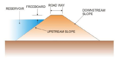
Figure 1. General shape of an embankment dam
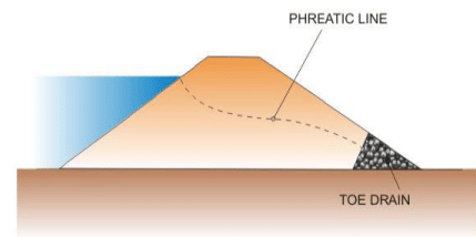
Figure 2. Homogeneons earthen embankment dam with toe drain
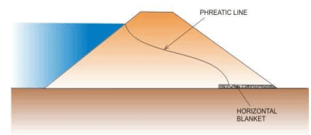
Figure 3.Homogeneous dam with horizontal blanket
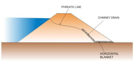
Figure 4. Homogeneous dam with inclined chimney drain connected to horizontal blanket
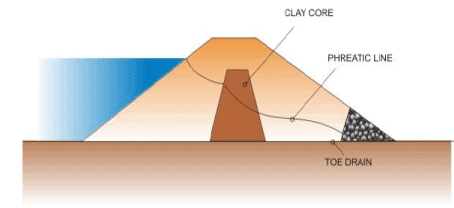
Figure 5. Zoned dam with central vertical day core and toe drain
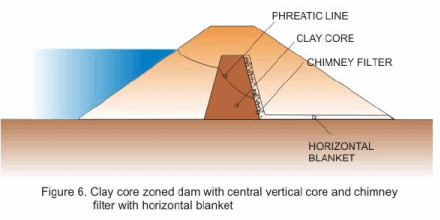
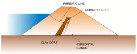
Figure 7. Inclined Clay core 2oned dam with chimney filter and horizontal blanket.
An embankment dam is not as impervious as a concrete dam and water continuously seeps through the dam body. In Figures 2 to 7, the position of the phreatic line (that is, the line corresponding to the phreatic surface lying above the saturated zone when seen in a vertical plane) has been marked in the respective figures. It may be noticed how the phreatic line is forced to remain within the dam body by providing the clay core (with relatively less permeability) to reduce the amount of seepage water and the chimney filter with the horizontal blanket, composed of materials with very high permeability, that is used to drain out the seepage water safely through the body of the dam.
For the rockfill embankment dams, the following variants are common:
- Central vertical clay core (Figure 8)
- Inclined clay core with drains (Figure 9)
- Decked with asphalt or concrete membrane on upstream face with drains (Figure 10)
All are provided with a chimney filter connected to a horizontal blanket.
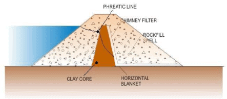
Figure 8. Rockfill dam with vertical clay core, chimney filter and horizontal blanket.
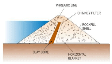
Figure 9 . Rock fill dam with inclined clay core, chimney drain and horizontal blanket
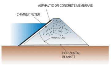
Figure 10. Decked rock fill dam with upstream asphaltic or concrete membrane with chimney drain and horizontal blanket. The phreatic live is for the small amount of water that leaks through the cracks of the upstream membrane.
Here, too it may be observed that the clay core with relatively very low permeability or the asphaltic and concrete membranes serve to reduce the quantity of seepage water. The rockfill shell only serves as a support to the core or membrane. The phreatic line through the rock fill is very gently inclined due to the materials of high permeability.
Since both the upstream and downstream faces of an embankment are inclined, usually varying in the ratio of 1V:1.5H to 1V:2.0H, the plan view of such a dam in a river valley would look as shown in Figure 11.
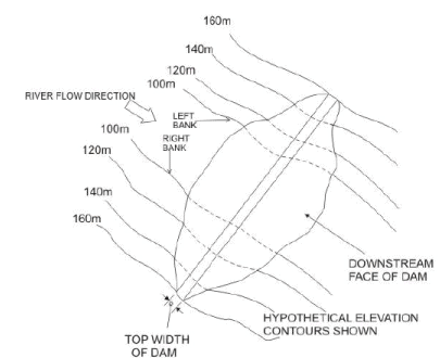
Figure 11. Layout of an embankment dam within a river valley
Though this is entirely satisfactory, the problem remains in providing a spillway to let out flood flows. This cannot be done through an embankment dam, since that would lead to its washout. Instead the spillway portion is usually made as a concrete gravity dam section, as shown in Figure 12 for the layout of Konar Dam on Konar river, in Jharkhand.
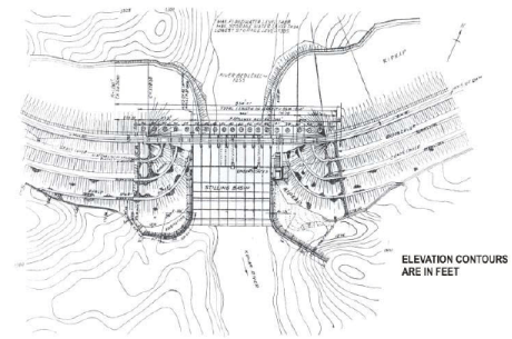
Figure 12. Layout of Konar Dam on River Konar, and located in Jharkhand (Drawing courtesy: CBIP Publication 138, volume II)
Typical cross section through the embankment portion and the spillway portion are shown in Figure13.
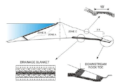
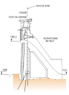
Figure 13. Cross sections of embankment dam and concrete gravity dam spillway of Konar dam shown in Figure 12
Another layout of the combination of an earthen embankment dam and a concrete spillway is shown in Figure14, for Ukai dam on Tapi river, in Gujarat.
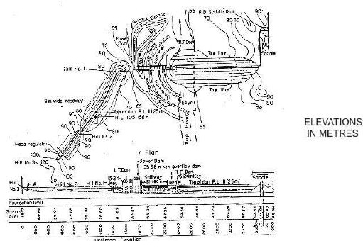
Figure 14 . Layout of Ukai dam- showing concrete spillway and embankment dam
Typical cross sections of the two types of embankment dam section used in the project is shown in Figure 15.
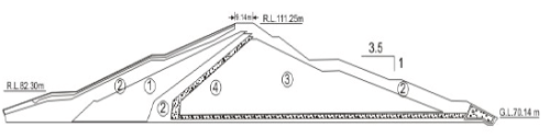
Legend
1, Impervious material
2, Semi-previous material
3, Random fill (material available from excavation)
4, Filter

Legend
1. Impervious zone 6. Silt zone
2. Semi-previous zone 7. Sand zone 3- Random zone
4. Sand Filter
5. Rock zone
Figure 15. Typical section of embankment dams constructed in Ukai project
Both the spillway section and the power dam section conveying penstock for power houses are made of concrete and are shown in Figures 16 and 17 respectively.
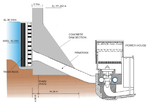
Figure 16. Typical power-dam section Ukai project
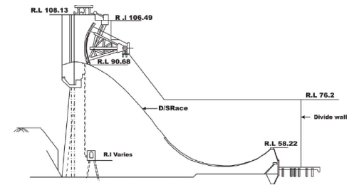
Figure 17. Cross-Section of Spillway Section of Ukai Dam Project
The example of Beas Dam at Pong (Figure 18) may be cited to show a typical layout for outlet work through the embanked section (Figure19).
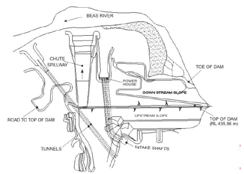
Figure 18 . Layout of Beas dam at Pong
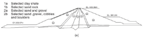
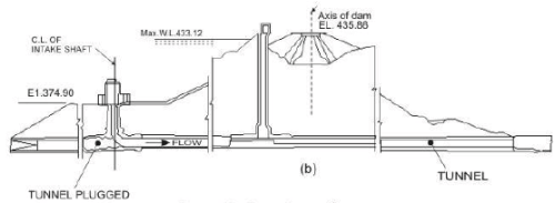
Figure 19. Beas dam at Pong
(a) Maximum section of earth dam
(b) Outlet work for power house through earth dam section
Another example is given in Figure 20 of the Wasco Dam, on Clear Creek, U.S.A, which shows an emergency spillway excavated out of left abutment hills and outlet work using rectangular duct through the bottom of the embankment dam (Figure 21).
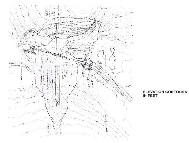
Figure 20. General layout of Wasco Dam, Clear Creek,USA Image courtesy: "Design of Small Dams", published by USBR
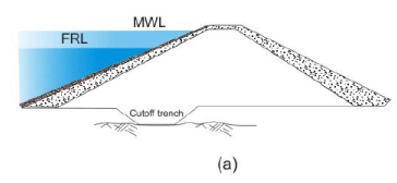
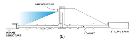
Figure 21. Cross sectional details of embankment dam shown in Figure 19.
(a) Through maximum section
(b) Through outlet work
FAQs on Design and Construction of Concrete Gravity Dams (Part -7)
| 1. What is the purpose of a concrete gravity dam and how does it resist water pressure? |  |
| 2. How do you calculate the stability of a concrete gravity dam against sliding and overturning? | |
| 3. What are the main construction challenges when building a concrete gravity dam in the field? | |
| 4. Why do concrete gravity dams develop cracks and how can they be prevented during design? | |
| 5. What is the difference between uplift pressure and seepage in concrete gravity dam foundations? | |

