Inductive Transducers | Sensor & Industrial Instrumentation - Electronics and Communication Engineering (ECE) PDF Download
Inductive Transducers
Inductive transducer is a simple and most popular type of displacement transducer in which variation of inductance as a function of displacement is achieved by variation in self inductance or mutual inductance. In general the value of self inductance of an inductor is given by:
L = N2 / S....(1)
where, N = Number of the coil
S = Reluctance of the coil (A/Wb)
But the reluctance S is given by
S = ℓ / μa....(2)
Hence self inductance L is given by,
L =N2μa....(3)
where N = Number of turns of coil.
μ = Permeability of core (H/m)
a = Area of magnetic circuit through which flux is passing (m2)
ℓ = Length of the magnetic circuit (m)
Thus the variation in the self inductance may be due to:
(i) Change in number of turns
(ii) Change in reluctance
(iii) Change in permeability.
The mutual inductance between the two coils is given by .... (4)
where M = mutual inductance between two coils.
k = coefficient of coupling
The mutual inductance between two coils can be varied by varying either self inductances of the coils or coefficient of coupling.
In general, inductive transducers are used for the measurement of physical quantities such as displacement, force, pressure, velocity, position, vibration etc. Let us study few types of inductive transducers.
Transducer Based on Principle of Change in Self Inductance with Number of Turns
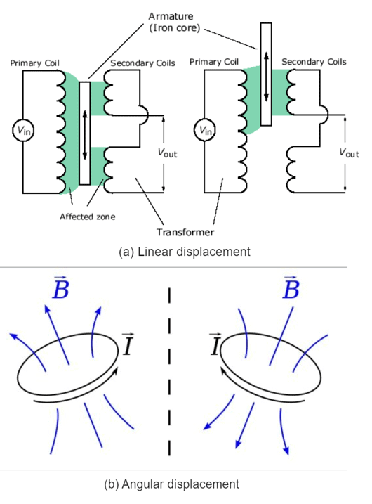
From the expression of the self inductance it is clear that L is directly proportional to N2 i.e. square of the number of turns. This property can be used to measure linear as well as angular displacement as shown in the Fig. 9.13. Fig. 9.13 Inductive transducer based on change in self inductance
Variable Permeability Inductive Transducer
The value of self inductance of a coil also depends on the permeability π. The transducer based on variable permeability is as shown in the Fig. 9.14. Fig. 9.14 Variable permeability inductive transducer. In this transducer, the displacement to be measured is applied to the rod which moves in and out of ferrite core according to the direction of the displacement. When iron core moves in, the effective permeability increases, while when iron core moves out, the effective permeability decreases and accordingly output voltage changes.
Variable Reluctance Inductive Transducer
The self inductance L is inversely proportional to the reluctance S. A variable reluctance type inductive transducer is as shown in the Fig. 9.15. It is a self generating type transducer. Fig. 9.15 Variable reluctance inductive transducerFig. 9.15 Variable reluctance inductive transducer A coil is wound by C shaped ferromagnetic core with a target plate placed above core with a small air gap. The size of this air gap determines the reluctance of the magnetic circuit, which in turn decides the self inductance. The displacement to be measured is applied to the target plate. According to the displacement, the target plate moves which changes the air gap and hence the self inductance. Thus for different air gaps we get different values of inductance hence we get different output voltage.
Eddy Current Type Inductive Transducer
An eddy current type inductive transducer is as shown in the Fig. 9.16. It is a self generating type transducer.
A non-ferrous plate moves in a direction perpendicular to the lines of flux of a magnet. The eddy currents are generated in a plate which are proportional to the velocity of the plate. These currents set up a magnetic field in a direction opposing the magnetic field producting these currents. Thus the output is proportional to the change in eddy current or the acceleration of the plate. As the air gap between the magnet and the plate remains constant, the transducer characteristics are linear. Fig. 9.16 Eddy current type inductive transducer
Linear Variable Displacement Transducer (LVDT)
Displacement is a vector quantity representing a change in position of a body or a point with respect to a reference. It can be linear or angular (rotational) motion. With the help of displacement transducer, many other quantities, such as force, stress, pressure, velocity, and acceleration can be found. In case of linear displacement, the magnitude of measurement may range from a few micrometer to a few centimeters. A majority of displacement transducers detect the static or dynamic displacement by means of suitable mechanical links coupled to the point or body whose displacement is to be measured.
The main electrical displacement transducers work on the principle of:
(i) Variable resistance: transducer is strain gauge.
(ii) Variable inductance: transducer is linear variable differential transformer
(iii) Variable capacitance: transducer is parallel plate capacitor with variable gap
(iv) Synchros and resolvers: used to measure angular displacement.
A simple and more popular type of displacement transducer is the variable inductance type wherein the inductance is varied according to the displacement. This is achieved either by varying the mutual inductance between the two coils (linear variable differential transformer) or by varying self inductances (variable reluctance sensor).
The very fine resolution, high accuracy, and good stability make LVDT most suitable as a position - measuring device. LVDT forms the basic sensing element in the measurement of pressure, load, and acceleration. It is also a basic element of electronic comparators, thickness - measuring units, and level indicators.
➢ Construction and Working of LVDT
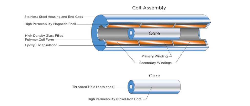
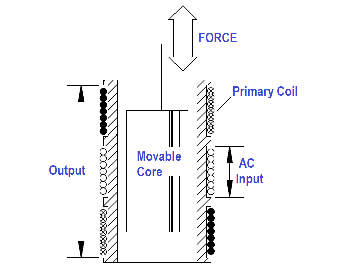
As illustrated in the Fig. 9.17, the linear variable differential transformer consists of a single primary winding Pi and two secondary windings Si and S2 wound on a hollow cylindrical former. The secondaries have an equal number of turns but they are connected in series opposition so that the e.m.f.s induced in the coils oppose each other. The primary winding is connected to an a.c. source, whose frequency may range from 50 Hz to 20 kHz. A movable soft iron core slides inside the hollow former. The position of the movable core determines the flux linkage between the a.c. excited primary winding and each of the two secondary windings. The core made up of nickel-iron alloy is slotted longitudinally to reduce eddy current losses. The displacement to be measured is applied to an arm attached to the core. With the core in the center, or reference, position, the induced e.m.f.s in the secondaries are equal, and since they oppose each other, the output voltage will be zero volt. Fig. 9.17 Linear variable differential transformer When an externally applied force moves the core to the left-hand position, more magnetic flux links the left-hand coil than the right-hand coil. The e.m.f. induced in the left-hand coil, Es1, is therefore larger than the induced e.m.f. of the right-hand coil, Es2. The magnitude of the output voltage is then equal to the difference between the two secondary voltages and it is in phase with the voltage of the left-hand coil.
Similarly, when the core is forced to move to the right, more flux links the right-hand coil than the left-hand coil and the resulting output voltage, which is the difference between Es2 and Es1, is now in phase with the e.m.f. of the right-hand coil. Fig. 9.18 Output voltage of LVDT at different core positions
Thus the LVDT output voltage is a function of the core position. The amount of a voltage change in either secondary winding is proportional to the amount of movement of the core. By noting which output is increasing or decreasing, the direction of motion can be determined. The output a.c. voltage inverts in phase as the core passes through the central null position. Further as the core moves from the center, the greater is the difference in value between E,, and and consequently the greater the output voltage. Therefore the amplitude of the output voltage is a function of the distance the core moves, while the polarity or phase indicates the direction of the motion.
The amount of output voltage of an LVDT is a linear function of the core displacement within a limited range of motion.
➢ Advantages and Disadvantages of LVDT
Advantages of LVDT:
- Linearity: The output voltage of LVDT is almost linear for displacement upto 5 mm.
- Infinite resolution: The change in output voltage is continuous, stepless. The effective resolution depends more on the equipment used for the measurement rather than on the LVDT.
- High output: LVDT gives reasonably high output, and hence requires less amplification afterwards.
|
23 videos|24 docs|29 tests
|
FAQs on Inductive Transducers - Sensor & Industrial Instrumentation - Electronics and Communication Engineering (ECE)
| 1. What is an inductive transducer? |  |
| 2. How does an inductive transducer work? |  |
| 3. What are the advantages of using inductive transducers? |  |
| 4. What are the applications of inductive transducers? |  |
| 5. How to calibrate an inductive transducer? |  |

|
Explore Courses for Electronics and Communication Engineering (ECE) exam
|

|


