Introduction to Additive Manufacturing | Manufacturing Engineering - Mechanical Engineering PDF Download
| Table of contents |

|
| Introduction |

|
| Prototype |

|
| Rapid Prototyping |

|
| Classification of Rapid Prototyping Systems |

|
| Liquid-based RP Systems |

|
| Additive manufacturing Techniques |

|
Introduction
The current marketplace is experiencing a rapid pace of change, compelling companies to develop new techniques to quickly adapt to the ever-evolving global environment. A country's economic health significantly relies on the creation of innovative products with shorter development cycles. Organizations' success or failure now hinges on their ability to swiftly meet changing customer demands and leverage new, cutting-edge technologies.
Prototype
A prototype is the initial or preliminary version of a product from which other versions are developed. It serves as a model from which further models and eventually the final product will be derived.
Rapid Prototyping
Rapid prototyping (RP) encompasses a range of technologies that can automatically create physical models from Computer-Aided Design (CAD) data. It involves quickly producing a representation of a system or part before its final release or commercialization. This process allows for the fabrication of a physical, three-dimensional part of any shape directly from a numerical description (usually a CAD model) through a fast, fully automated, and highly flexible method.
Alternative names for RP
- Additive Manufacturing
- Layer Manufacturing
- Direct CAD Manufacturing
- Solid Freeform Fabrication
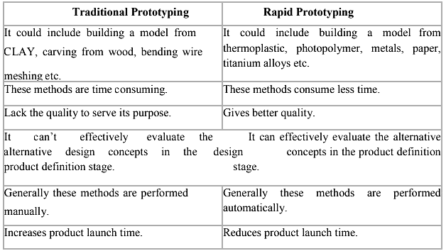
Traditional Prototyping Vs. Rapid Prototyping
Classification of Rapid Prototyping Systems
The development of rapid prototyping (RP) can be categorized into four main areas. These key aspects are illustrated in the Rapid Prototyping Wheel shown below. They include: Input, Method, Material, and Applications.
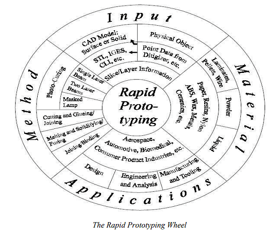
While there are many ways in which one can classify the numerous RP systems in the market, one of the better ways is to classify RP systems broadly by the initial form of its material, i.e. the material that the prototype or part is built with.
In this manner, all RP systems can be easily categorized into
(1) liquid-based (2) solid- based and (3) powder-based.
Liquid-based RP Systems
Liquid-based RP systems utilize materials in a liquid state as their initial form. Through a process known as curing, the liquid material is transformed into a solid state.
The following RP systems fall into this category:
- 3D Systems’ Stereolithography Apparatus (SLA)
- Cubital’s Solid Ground Curing (SGC)
- Sony’s Solid Creation System (SCS)
- CMET’s Solid Object Ultraviolet-Laser Printer (SOUP)
- Autostrade’s E-Darts
- Teijin Seiki’s Soliform System
- Meiko’s Rapid Prototyping System for the Jewelry Industry
- Denken’s SLP
- Mitsui’s COLAMM
- Fockele & Schwarze’s LMS
- Light Sculpting
- Aaroflex
- Rapid Freeze
- Two Laser Beams
- Microfabrication
Each of these RP systems will be described in more detail in the following chapters. The table below shows some key RP systems and the materials used for each particular technology.
RP systems and related base materials
Additive manufacturing Techniques
1. Laser Engineered Net Shaping (LENS):
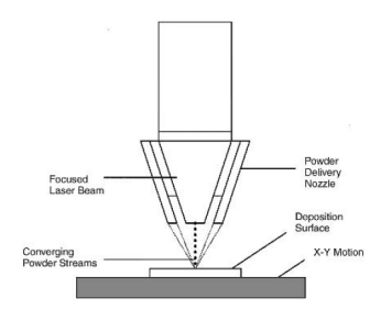
The LENSTM process constructs components additively from powdered metals using a Nd: YAG laser to fuse the powder into a solid, as illustrated in Figure 5.15. This method represents a freeform metal fabrication process that results in fully dense metal components. The LENSTM process includes the following steps.
Steps:
- A deposition head delivers metal powder to the focus of a high-powered Nd
- laser beam, which melts the powder. This laser is typically guided by fiber optics or precision-angled mirrors.
- The laser is focused on a specific spot using a series of lenses, while a motion system beneath the platform moves horizontally and laterally as the laser beam traces the cross-section of the part being produced.
- The fabrication process occurs in a low-pressure argon chamber to ensure an oxygen-free environment in the melting zone, promoting good adhesion.
- Once a layer is completed, the deposition head moves up to continue with the next layer. This process repeats layer by layer until the part is finished. The entire process is usually enclosed to isolate it from the atmosphere. Generally, the prototypes require additional finishing but are fully dense products with good grain formation.
Principle:
A high-powered Nd
- laser focused onto a metal substrate creates a molten puddle on the substrate surface. Powder is then injected into the molten puddle to increase the material volume.
- A "printing" motion system moves a platform horizontally and laterally as the laser beam traces the cross-section of the part being produced. After forming a layer, the machine’s powder delivery nozzle moves upwards before building the next layer.
Advantages:
- Superior material properties: The LENS process can produce fully dense metal parts with embedded structures and superior material properties, including a good microstructure.
- Complex parts: The LENS system excels at producing functional metal parts with complex features.
- Reduced post-processing requirements: Post-processing is minimized, reducing cycle time.
Disadvantages:
- Limited materials: The process is currently limited to producing only metal parts.
- Large physical unit size: The unit requires a relatively large area.
- High power consumption: The laser system requires very high wattage.
2. Direct Metal Deposition (DMD):
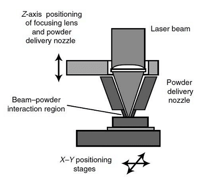
Direct laser deposition (DLD) or direct metal deposition (DMD) is a laser-assisted direct metal manufacturing process that uses computer-controlled lasers to weld air-blown streams of metallic powders into custom parts and manufacturing molds within hours. Some processes use wire instead of powder, but the concept is similar.
A representative process called Laser Engineered Net Shaping (LENS) uses CAD file cross-sections to control the forming process developed by Optomec Inc. The DLD process can be used throughout the entire product life-cycle for applications ranging from materials research to adding material to existing components for service and repair applications.
Powder-metal particles are delivered in a gas stream into the focus of a laser to form a molten pool of metal. This layer-by-layer additive rapid prototyping process allows the production of parts, molds, and dies made from the actual end-material, such as aluminum or tool steel.
The laser beam moves back and forth across the part, creating a molten pool of metal where a precise stream of metal powder is injected to increase its size. This process is a hybrid of several technologies: lasers, CAD, CAM, sensors, and powder metallurgy. It improves on other methods of metalworking by eliminating waste material and subtractive processes. Additionally, it can mix metals to specific standards and specifications in a way not previously possible.
Advantages:
- The strength of DLD lies in its ability to fabricate fully dense metal parts with excellent metallurgical properties at reasonable speeds.
- DLD is an efficient approach that reduces production costs and accelerates time to market for high-value components.
- DLD systems enable the fabrication of novel shapes, hollow structures, and material gradients that are otherwise infeasible.
Disadvantages:
Traditional DLD or RP processes use three-axis tables, often requiring support structures to build overhanging parts. These structures are undesirable in laser-based processes involving metals. High melting-point materials can be used to build support structures, which can then be removed using other processes, such as chemical etching.
3. Sheet Lamination (Laminated Object Manufacturing (LOM)):
There are two approaches to the LOM process:
I. Cut and then paste:
- Handling the cut pieces is difficult, if not impossible, because:
- More than one piece may need to be handled for each layer.
- The pieces may be oddly shaped.
- Paper, being flexible, further complicates handling.
- A support mechanism is required.
- This method is suitable for laminated tooling.
II. Paste and then cut:
- Handling is easy; indexing of the reel is all that is required.
- The remaining stock acts as the support material.
- The only drawback is the time-consuming decubing operation.
- This method is suitable for paper-like flexible materials.
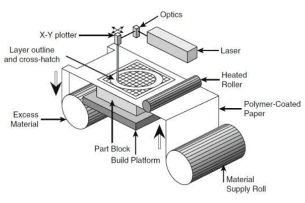
Steps:
- If multiple parts are to be made, an optimal packing arrangement must be determined (an automatic program for this is still not available). It is preferable to pack as many pieces as possible in processes such as LOM, SLS, SGC, and 3D Printing.
- Position and orient the object/cluster in the desired place. Some users tilt it by 10 to 15 degrees to avoid any surface becoming horizontal.
- Set the machine with the desired process parameters such as beam diameter, beam offset flag, grid sizes, number of dummy layers, bridging gap between two cuts, etc.
- Load the paper roll of appropriate width.
- Identify the location for the build on the table and feed it to the machine. Apply a double-sided adhesive in that zone.
- Each slice or layer is created using the following steps:
- The paper reel indexes by a fixed distance and has adhesive on the bottom surface.
- The table rises to the required height.
- A hot roller (laminating tool) rolls over it, causing it to stick to the previous layer.
- The height is measured and passed on to the slicing software.
- The loops of the slice are cut by the laser, with possible offsetting of the laser beam by the beam radius to compensate for it.
- Grid cutting around the bounding box of the stock follows, ensuring that the grids of all layers coincide. Finally, a parting off cut is made.
- The table lowers by a considerable distance so that the cut portion can be stripped off from the reel.
- The part is finished and painted as required. It can be given a lacquer coat to prevent moisture absorption.
Advantages:
- Only boundaries need to be addressed, not their interiors.
- It employs a CO2 laser, which is cheaper and does not require a protective environment.
- Paper is very cheap.
- It produces strong, wood-like parts, making it ideal for casting patterns.
Limitations:
- Grid cutting takes much more time than object cutting.
- Decubing is also time-consuming.
- Horizontal surfaces pose problems; although it is solvable, it has not been fully addressed to date.
4. 3D Printing:
This process is very similar to SLS, but instead of using a laser, a binder liquid is sprayed in selected regions. The raw material is powder. Concept models can be rapidly prepared using a multi-jet, multi-color spray over starch (ZCorp). Green parts will require sintering in another furnace.
When a binder is sprayed through thin nozzles on the selected region over a layer of powder, the particles in that region stick together. The remaining powder acts as a support, similar to LOM. The binder spray uses mechanical movement, and multiple jets make it faster. Explicit support structures are not required, and a wide variety of powders can be used.
Steps:
- The raw material is powder.
- The binder liquid is selectively deposited on the layer of powder.
- After deposition, the layer is cured, and then the unbound powder is separated.
5. Fused Deposition Modeling (FDM):
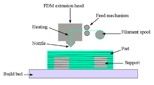
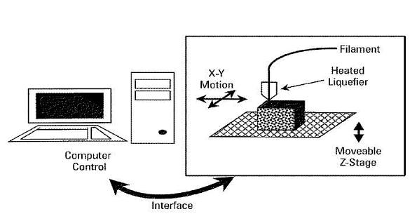
In this process, molten material inside a hot chamber is extruded through a nozzle. Using raw material in wire form as a consumable piston is an effective approach. The nozzle size alone does not determine the layer thickness and road width; these depend on the speed of the head and the wire feed speed. Their relationship can be understood through the principle of conservation of mass (similar to applying toothpaste to a brush).
Explicit support structures are required, so twin heads are used: one for the model and one for support.
Steps:
- The starting material is melted, and small droplets are shot by a nozzle onto the previously formed layer.
- The droplets cold weld to the surface to form a new layer.
- Deposition for each layer is controlled by a moving x-y nozzle, following a path based on a cross-section of a CAD geometric model that is sliced into layers.
- Work materials include wax and thermoplastics.
Advantages
- Any thermoplastic material can be used as long as the appropriate head is available.
- It does not employ lasers and hence no safety related issues.
- It does not use liquid.
- Powder raw materials and hence clean. It can be kept in an office environment as a3D printer.
- Very easy to remove the support. This is probably the easiest of all RP processes.
- This is the cheapest machine. However, this is also due to their business policy since the costs of all RP machines are comparable.
Limitations
- As every point of the volume is addressed by a „mechanical device“, it is very slow.
- Not very accurate compared SLA, SGC etc.
6. Electron Beam Melting (EBM):
Electron beam melting (EBM) has become a successful approach to Powder Bed Fusion (PBF). Unlike laser-based systems, EBM uses a high-energy electron beam to fuse metal powder particles. This process was developed at Chalmers University of Technology in Sweden and was commercialized by Arcam AB in 2001.
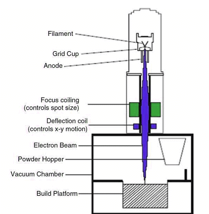
Laser beams heat the powder by photon absorption, while electron beams heat powder through the transfer of kinetic energy from incoming electrons to powder particles. As powder particles absorb electrons, they gain a negative charge, leading to two potential issues:
- If the repulsive force of neighboring negatively charged particles overcomes the gravitational and frictional forces holding them in place, it can cause a rapid expulsion of powder particles from the powder bed, creating a powder cloud (more problematic for fine powders than coarser powders).
- Increasing negative charges in the powder particles will repel incoming negatively charged electrons, creating a more diffuse beam.
These issues are not present with photons. Thus, the conductivity of the powder bed in EBM must be high enough to prevent powder particles from becoming highly negatively charged, and scanning strategies must avoid regions of negatively charged particles. In practice, electron beam energy is more diffuse to prevent excessive negative charge buildup in any one location, resulting in a larger heat-affected zone. Consequently, the minimum feature size, median powder particle size, layer thickness, resolution, and surface finish of an EBM process are typically larger than those of a mLS process.
As EBM requires a conductive powder bed, it can only process conductive materials (e.g., metals), whereas lasers can work with any material that absorbs energy at the laser wavelength (e.g., metals, polymers, and ceramics). Electron beam generation is generally more efficient than laser beam generation.
7. Selective Laser Sintering (SLS):
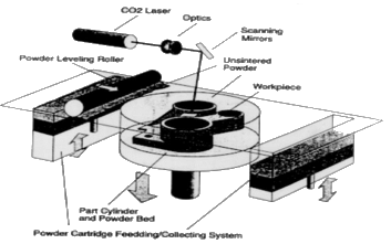
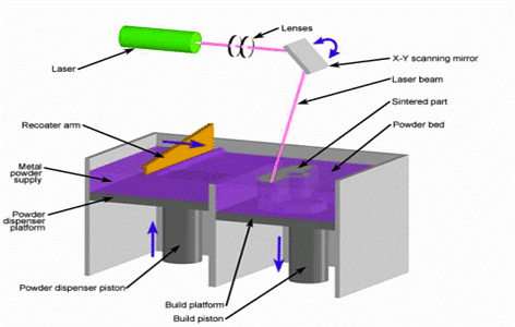
Developed by the University of Texas at Austin, SLS is marketed by DTM in the USA and EOS in Germany. The raw material is powder. The principle is similar to Powder Metallurgy but without compaction. A green part is prepared on the RP machine after partial sintering, and complete sintering occurs in another furnace.
Like SLA, laser light is used in SLS. When the laser is scanned over the selected region of a powder layer, the particles fuse together. The remaining powder acts as support, similar to LOM. The laser beam is positioned using a small mirror that can deflect in two directions, resulting in low inertia and thus high speed and accuracy. The laser's power determines the layer thickness. Explicit support structures are not required, and a wide variety of powders can be used.
Steps:
- Once slicing is complete, the working volume is maintained at an appropriate temperature so that the laser supplies the energy required to exceed the threshold sintering temperature. An inert environment is created using a continuous supply of gas, such as nitrogen, to minimize fire hazards since fine particles have high activation.
- Each slice or layer is created using the following steps:
- The table lowers by one layer thickness.
- A layer of powder is spread and leveled using a contra-rotating roller.
- The laser beam scans the layer of powder, selectively sintering the required region.
- After all layers are created, the table rises completely, revealing a block of cake with the part inside.
- The surrounding powder, which remains soft, is removed using suitable brushes and is reusable.
- The part is placed in a suitable hot chamber to complete the sintering process.
- Metallic prototypes may require copper impregnation in another furnace to improve their polishability.
- The part is finished and painted as required.
Advantages:
- A wide variety of powders can be used.
- The process is fast due to the tiny moving mirror parts, similar to SLA.
- Metallic parts can be produced.
- Suitable for making injection molding tools.
Limitations:
- Surface finish is less refined and dictated by the particle size.
- Z-axis accuracy is poor due to the absence of milling.
8. Photopolymerization (Stereolithography (SL)):
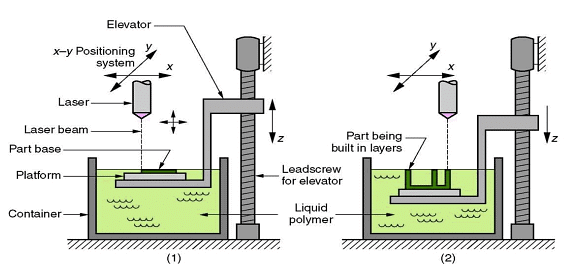
When light of an appropriate wavelength falls on a liquid photopolymer, the energy absorbed causes polymerization, solidifying the photopolymer. Laser light is used to scan the selected region over a layer of liquid polymer, solidifying that region. The remaining liquid can be drained.
The laser beam is positioned using a small mirror capable of deflecting in two directions, resulting in low inertia and thus high speed and accuracy. The power of the laser determines the layer thickness. Explicit support structures are required, achieved by modifying the geometry of the prototype, typically adding bristles and thin structures.
Steps:
- At the beginning of the process, the initial layer is added to the platform.
- As additional layers are added, the part geometry gradually takes form.
Process Details:
Support structures are automatically added to the model wherever necessary. Slicing is then performed.
Each slice or layer is created through the following steps:
- The table (known as a vat) dips and rises to the required Z level.
- A blade wipes off excess liquid.
- The laser beam scans the liquid layer, creating borders first and then filling areas in a grid pattern.
- After all layers are completed, the table rises completely, revealing the finished part.
Once the liquid has drained, it is removed from the table, and the support structure is carefully removed.
The part undergoes post-curing in an apparatus where it is exposed to UV radiation for approximately an hour, completing the polymerization process.
|
52 videos|86 docs|29 tests
|


