Logic Gates & Truth Tables | Digital Logic - Computer Science Engineering (CSE) PDF Download

Introduction

These are important digital devices that are mainly based on the Boolean function. Logic gates are used to carry out logical operations on single or multiple binary inputs and give one binary output. In simple terms, logic gates are the electronic circuits in a digital system.

Types of Basic Logic Gates

There are several basic logic gates used in performing operations in digital systems. The common ones are;

  • OR Gate
  • AND Gate
  • NOT Gate
  • XOR Gate

Additionally, these gates can also be found in a combination of one or two. Therefore we get other gates such as NAND Gate, NOR Gate, EXOR Gate, and EXNOR Gate.

OR Gate
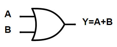
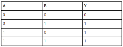
In an OR gate, the output of an OR gate attains state 1 if one or more inputs attain state 1.
Logic Gates & Truth Tables | Digital Logic - Computer Science Engineering (CSE)

The Boolean expression of the OR gate is Y = A + B, read as Y equals A ‘OR’ B.

The truth table of a two-input OR basic gate is given as;
Logic Gates & Truth Tables | Digital Logic - Computer Science Engineering (CSE)

AND Gate
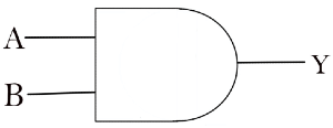
In the AND gate, the output of an AND gate attains state 1 if and only if all the inputs are in state 1.
Logic Gates & Truth Tables | Digital Logic - Computer Science Engineering (CSE)

The Boolean expression of AND gate is Y = A.B

The truth table of a two-input AND basic gate is given as;
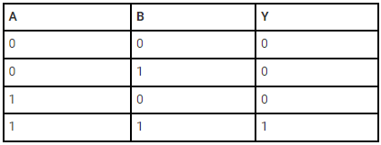
Logic Gates & Truth Tables | Digital Logic - Computer Science Engineering (CSE)

NOT Gate
In a NOT gate, the output of a NOT gate attains state 1 if and only if the input does not attain state 1.

Logic Gates & Truth Tables | Digital Logic - Computer Science Engineering (CSE)

The Boolean expression is:

Logic Gates & Truth Tables | Digital Logic - Computer Science Engineering (CSE)

It is read as Y equals NOT A.

The truth table of NOT gate is as follows;

Logic Gates & Truth Tables | Digital Logic - Computer Science Engineering (CSE)

When connected in various combinations, the three gates (OR, AND and NOT) give us basic logic gates such as NAND, and NOR gates, which are the universal building blocks of digital circuits.

NAND Gate
This basic logic gate is the combination of AND and NOT gates.

Logic Gates & Truth Tables | Digital Logic - Computer Science Engineering (CSE)

The Boolean expression of the NAND gate is:

Logic Gates & Truth Tables | Digital Logic - Computer Science Engineering (CSE)

The truth table of a NAND gate is given as;
Logic Gates & Truth Tables | Digital Logic - Computer Science Engineering (CSE)

NOR Gate
This gate is the combination of OR and NOT gate.
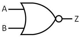
Logic Gates & Truth Tables | Digital Logic - Computer Science Engineering (CSE)

The Boolean expression of NOR gate is:
Logic Gates & Truth Tables | Digital Logic - Computer Science Engineering (CSE)

The truth table of a NOR gate is as follows;
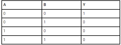
Logic Gates & Truth Tables | Digital Logic - Computer Science Engineering (CSE)

Exclusive-OR gate (XOR Gate)
In an XOR gate, the output of a two-input XOR gate attains state 1 if one adds only input attains state 1.

Logic Gates & Truth Tables | Digital Logic - Computer Science Engineering (CSE)

The Boolean expression of the XOR gate is:
Logic Gates & Truth Tables | Digital Logic - Computer Science Engineering (CSE)
The truth table of an XOR gate is;
Logic Gates & Truth Tables | Digital Logic - Computer Science Engineering (CSE)

Exclusive-NOR Gate (XNOR Gate)
In the XNOR gate, the output is in state 1 when both inputs are the same, that is, both 0 or both 1.

Logic Gates & Truth Tables | Digital Logic - Computer Science Engineering (CSE)

The Boolean expression of the XNOR gate

Logic Gates & Truth Tables | Digital Logic - Computer Science Engineering (CSE)

The truth table of an XNOR gate is given below;

Logic Gates & Truth Tables | Digital Logic - Computer Science Engineering (CSE)

Application Of Logic Gates

Logic gates have a lot of applications, but they are mainly based upon their mode of operations or their truth table. Basic logic gates are often found in circuits such as safety thermostats, push-button locks, automatic watering systems, light-activated burglar alarms and many other electronic devices.

One of the primary benefits is that basic logic gates can be used in various combinations if the operations are advanced. Besides, there is no limit to the number of gates that can be used in a single device. However, it can be restricted due to the given physical space in the device. In digital integrated circuits (ICs), we will find an array of the logic gate area unit.

De Morgan’s Theorem

First theorem – It states that the NAND gate is equivalent to a bubbled OR gate.
Logic Gates & Truth Tables | Digital Logic - Computer Science Engineering (CSE)

Second theorem – It states that the NOR gate is equivalent to a bubbled AND gate.

Logic Gates & Truth Tables | Digital Logic - Computer Science Engineering (CSE)

Important Conversions

(1) The ‘NAND’ gate: From ‘AND’ and ‘NOT’ gate
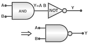
Logic Gates & Truth Tables | Digital Logic - Computer Science Engineering (CSE)

Boolean expression and truth table:

Logic Gates & Truth Tables | Digital Logic - Computer Science Engineering (CSE)

(2) The ‘NOR’ gate: From ‘OR’ and ‘NOT’ gate

Logic Gates & Truth Tables | Digital Logic - Computer Science Engineering (CSE)

Boolean expression and truth table:
Logic Gates & Truth Tables | Digital Logic - Computer Science Engineering (CSE)

(3) The ‘XOR’ gate: From ‘NOT’, ‘AND’ and  ‘OR’ gate.
The logic gate, which gives a high output (i.e., 1) if either input A or input B but not both are high (i.e. 1), is called the exclusive OR gate or the XOR gate. It may be noted that if both the inputs of the XOR gate are high, then the output is low (i.e., 0).

Logic Gates & Truth Tables | Digital Logic - Computer Science Engineering (CSE)

Logic Gates & Truth Tables | Digital Logic - Computer Science Engineering (CSE)

Boolean expression and truth table:
Logic Gates & Truth Tables | Digital Logic - Computer Science Engineering (CSE)

Logic Gates & Truth Tables | Digital Logic - Computer Science Engineering (CSE)

(4) The Exclusive nor (XNOR) gate XOR + NOT
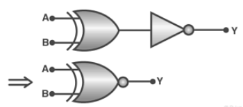
Logic Gates & Truth Tables | Digital Logic - Computer Science Engineering (CSE)

Boolean expression:
Logic Gates & Truth Tables | Digital Logic - Computer Science Engineering (CSE)

Logic Gates & Truth Tables | Digital Logic - Computer Science Engineering (CSE)

The document Logic Gates & Truth Tables | Digital Logic - Computer Science Engineering (CSE) is a part of the Computer Science Engineering (CSE) Course Digital Logic.
All you need of Computer Science Engineering (CSE) at this link: Computer Science Engineering (CSE)
32 docs|15 tests

Top Courses for Computer Science Engineering (CSE)

FAQs on Logic Gates & Truth Tables - Digital Logic - Computer Science Engineering (CSE)

1. What are logic gates and truth tables in computer science engineering?
Ans. Logic gates are basic building blocks of digital circuits that perform logical operations on one or more binary inputs to produce a single binary output. Truth tables, on the other hand, are tables that represent the relationship between inputs and outputs of logic gates, showing all possible input combinations and their corresponding outputs.
2. How many types of logic gates are there?
Ans. There are seven basic types of logic gates: AND, OR, NOT, NAND, NOR, XOR, and XNOR. Each gate has its own unique logic and truth table.
3. What is the purpose of logic gates in computer science engineering?
Ans. Logic gates are used to design and build digital circuits that perform various logical operations, such as arithmetic computations, data processing, and decision making. They are fundamental in constructing complex digital systems like microprocessors and computer memory.
4. How do logic gates work?
Ans. Logic gates work by combining binary inputs (0s and 1s) based on their specific logic and producing a binary output. Each gate follows a predefined truth table that defines the output based on the input combination. For example, an AND gate outputs 1 only when both inputs are 1; otherwise, it outputs 0.
5. Can logic gates be combined together?
Ans. Yes, logic gates can be combined together to create more complex logic functions. This is achieved by connecting the output of one gate to the input of another gate, forming a cascaded circuit. By combining different gates, engineers can design circuits that perform more sophisticated operations and fulfill specific requirements.
32 docs|15 tests
Download as PDF
Explore Courses for Computer Science Engineering (CSE) exam

Top Courses for Computer Science Engineering (CSE)

Signup for Free!
Signup to see your scores go up within 7 days! Learn & Practice with 1000+ FREE Notes, Videos & Tests.
10M+ students study on EduRev
Related Searches

past year papers

,

practice quizzes

,

study material

,

Viva Questions

,

Summary

,

shortcuts and tricks

,

mock tests for examination

,

Important questions

,

MCQs

,

Objective type Questions

,

pdf

,

Sample Paper

,

video lectures

,

Previous Year Questions with Solutions

,

Semester Notes

,

Exam

,

Free

,

Logic Gates & Truth Tables | Digital Logic - Computer Science Engineering (CSE)

,

Logic Gates & Truth Tables | Digital Logic - Computer Science Engineering (CSE)

,

Extra Questions

,

Logic Gates & Truth Tables | Digital Logic - Computer Science Engineering (CSE)

,

ppt

;