Measurement of Mutual Inductance | GATE Notes & Videos for Electrical Engineering - Electrical Engineering (EE) PDF Download
Heaviside Mutual Inductance Bridge
Heaviside Bridge measures mutual inductance in terms of a known self-inductance. The same bridge, slightly modified, was used by Campbell to measure a self-inductance in terms of a known mutual inductance.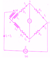
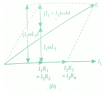
Measurement of Mutual Inductance By Heaviside Bridge
Let M = unknown mutual inductance,
L1 = self-inductance of secondary of mutual inductance,
L2 =known self-inductance, and
R1, R2, R3, R4 = non-inductive resistors.
At balance voltage drop between b and c must equal the voltage drop between d and c. Also, the voltage drop across a-b-c must equal the voltage drop across a-d-c. Thus we have the following equations at balance.
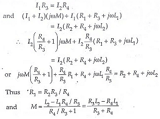
It is clear from the above equation, that L1, the self inductance of the secondary of the mutual inductor must be known in order that M be measured by this Heaviside Bridge method.
In case R3 = R4
we get M = (L2 - L1)/2 and R1= R2
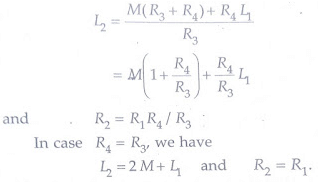
Heaviside Bridge method can be used for measurement of self-inductance. Supposing L2 is the self-inductance to be determined. From above equations, we get
Campbell’s Modification of Heaviside Bridge
- The below figure shows a modified Heaviside bridge. This modification is due to Campbell. This is used to measure a self-inductance in terms of a mutual inductance. In this case, an additional balancing coil R is included in arm a-d in series with inductor under test. An additional resistance r is put in arm a-b. Balance is obtained by varying M and r.
- A short circuiting switch is placed across the coil R2, L2 under measurement. Two sets of readings are taken one with switch being open and the other with switch being closed. Let values of M and r, be M1 and r1 with switch open, and M2 and r2 with switch closed.
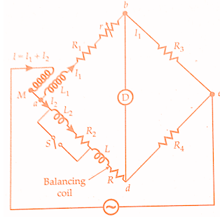
With switch open from above equation we have,

Hence L2 = (M1 M2)(1 + R4/R3)
With switch open, we have, R2+ R = (R1 + r1)R4/R3
and with the switch closed
R = (R1 + r2)R4/R3
R2 = (r1 - r2) R4/R3
This method is a good example of the methods adopted to eliminate the effects of leads etc.
When we have equal ratio arms R3 = R4
and therefore from above equations we get,
L2 = (M1 - M2) and R2 = (r1 - r2)
Heaviside Campbell Equal Ratio Bridge
The use of balancing coil in the above method reduces the sensitivity of the bridge.The below figure shows Heaviside Campbell equal ratio bridge. This is a better arrangement which improves sensitivity and also dispenses with the use of a balancing coil.In this method, the secondary of the mutual inductor is made up of two equal coils each having a self-inductance.
- One of the coils is connected in arm ab and the other in arm a-d.The primary of mutual inductance reacts with both of them.L2, R2 is the coil whose self-inductance and resistance is to be determined.The resistances R3 and R4 are made equal.Balance is obtained by varying the mutual inductance and resistance r.
At balance I1R3 = I2R4 but R3 = R4
and therefore I1 = I2 = I/2 as I = I1 + I2
Writing the other equation for balance

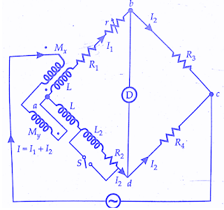 Equating the real and imaginary terms
R2 = R1 + r and L2 =2(Mx + My)=2M
Thus the magnitude of inductance measured with this method is twice the range of the mutual inductor. The values calculated above include the effects of leads etc. In order to eliminate these effects, we take two readings with the switch open circuited and another with the switch closed. Let M1, r1 be the readings of M, r with open circuit and M2, r2 with the short circuit.
R1 = (r1-r2) and L1 = 2(M1-M2)
|
27 videos|333 docs
|


