Measuring Flow Rate | Sensor & Industrial Instrumentation - Electronics and Communication Engineering (ECE) PDF Download
Flow Rate
Many flow measurement instruments use indirect measurements, such as differential pressures, to measure the flow rate. These instruments measure the differential pressures produced when a fluid flows through a restriction. Differential pressure measuring sensors were discussed in Chapter 7. The differential pressure produced is directly proportional to flow rate. Such commonly used restrictions are the (a) orifice plate, (b) Venturi tube, (c) flow nozzle, and (d) Dall tube. ➢ The orifice plate is normally a simple metal diaphragm with a constricting hole. The diaphragm is normally clamped between pipe flanges to give easy access. The differential pressure ports can be located in the flange on either side of the orifice plate, or alternatively, at specific locations in the pipe on either side of the flange, as
Table 9.4 Typical Drag Coefficient Values for Objects Immersed in Flowing Fluid
determined by the flow patterns (named vena contracta), as shown in Figure 9.5. Shown also is the pressure profile. A differential pressure gauge is used to measure the difference in pressure between the two ports. The differential pressure gauge can be calibrated in flow rates. The lagging edge of the hole in the diaphragm is beveled to minimize turbulence. In fluids, the hole is normally centered in the diaphragm, as shown in Figure 9.6(a). However, if the fluid contains particulates, the hole could be placed at the bottom of the pipe, as shown in Figure 9.6(b), to prevent a buildup of particulates. The hole also can be in the form of a semicircle having the same diameter as the pipe, and located at the bottom of the pipe, as shown in Figure 9.6(c).
The flow rate Q in a differential flow rate meter is given by:
where K is the flow coefficient constant, dS is the diameter of the orifice, dP is the pipe diameter, and h is the difference in height between PH and PL.
➢ The Venturi tube, shown in Figure 9.7(a), uses the same differential pressure principal as the orifice plate. The Venturi tube normally uses a specific reduction in tube size, and is normally well suited for use in larger diameter pipes, but it becomes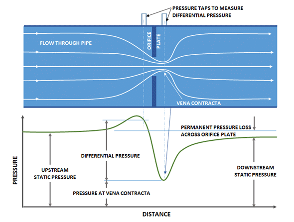 Figure 9.5 Orifice constriction plate with pressure profile.
 Figure 9.6 Orifice shapes and locations used (a) with fluids, and (b, c) with suspended solids.
heavy and excessively long. One advantage of the Venturi tube is its ability to handle large amounts of suspended solids. It creates less turbulence and insertion loss than the orifice plate. The differential pressure taps in the Venturi tube are located at the minimum and maximum pipe diameters. The Venturi tube has good accuracy, but is expensive.
➢ The flow nozzle is a good compromise on cost and accuracy between the orifice plate and the Venturi tube for clean liquids. It is not normally used with suspended particles. Its main use is the measurement of steam flow. The flow nozzle is shown in Figure 9.7(b).
➢ The Dall tube, as shown in Figure 9.7(c), has the lowest insertion loss, but is not suitable for use with slurries.
➢ A typical ratio (i.e., a beta ratio, which is the diameter of the orifice opening (d) divided by the diameter of the pipe (D)) for the size of the constriction of pipe size in flow measurements is normally between 0.2 and 0.6. The ratios are chosen to give sufficiently high pressure drops for accurate flow measurements, but not high enough to give turbulence. A compromise is made between high beta ratios (d/D), which give low differential pressures, and low ratios, which give high differential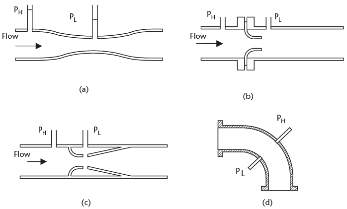 Figure 9.7 Types of constrictions used to measure flow: (a) Venturi tube, (b) flow nozzle, (c) Dall tube, and (d) elbow.
pressures but can create high losses. The Dall tube has the advantage of having the lowest insertion loss, but it cannot be used with slurries.
➢ The elbow can be used as a differential flow meter. Figure 9.7(d) shows the cross section of an elbow. When a fluid is flowing, there is a differential pressure between the inside and outside of the elbow, due to the change in direction of the fluid. The pressure difference is proportional to the flow rate of the fluid. The elbow meter is good for handling particulates in solution, and has good wear and erosion resistance characteristics, but has low sensitivity.
In an elbow, the flow is given by:
where C is a constant, R is the center line radius of the elbow, PD is the differential pressure, D is the diameter of the elbow, and is the density of the fluid.
➢ The pilot static tube, as shown in Figure 9.8, is an alternative method of measuring flow rate, but has a disadvantage, in that it really measures fluid velocity at the nozzle. Because the velocity varies over the cross section of the pipe, the pilot static tube should be moved across the pipe to establish an average velocity, or the tube should be calibrated for one area. Other disadvantages are that the tube can become clogged with particulates, and that the differential pressure between the impact and static pressures for low flow rates may not be enough to give the required accuracy. The differential pressures in any of the above devices can be measured using the pressure measuring sensors.
In a pilot static tube, the flow Q is given by:
where K is a constant, ps is the static pressure, and p1 is the impact pressure.
➢ Variable-area meters, such as the rotameter shown in Figure 9.9(a), are often used as a direct visual indicator for flow rate measurements. The rotameter is a vertical tapered tube with a T (or similar) shaped weight, and the tube is graduated in flow rate for the characteristics of the gas or liquid flowing up the tube. The velocity of a fluid or gas flowing decreases as it goes higher up the tube, due to the increase in the bore of the tube. Hence, the buoyancy on the weight reduces as it goes higher up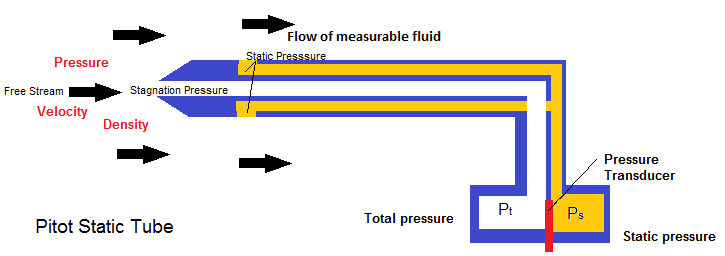 Figure 9.8 Pilot static tube.
the tube. An equilibrium point is eventually reached, where the force on the weight due to the flowing fluid is equal to that of the weight (i.e., the higher the flow rate, the higher the weight goes up the tube). The position of the weight also is dependent on its size and density, the viscosity and density of the fluid, and the bore and taper of the tube. The rotameter has low insertion loss, and has a linear relationship to flow rate. In cases where the weight is not visible, such as an opaque tube used to reduce corrosion, it can be made of a magnetic material, and tracked by a magnetic sensor on the outside of the tube. The rotameter can be used to measure differential pressures across a constriction or flow in both liquids and gases [3].
➢ Vortex flow meters are based on the fact that an obstruction in a fluid or gas flow will cause turbulence or vortices. In the case of the vortex precession meter (for gases), the obstruction is shaped to give a rotating or swirling motion forming vortices, which can be measured ultrasonically. See Figure 9.9(b). The frequency of the vortex formation is proportional to the rate of flow. This method is good for high flow rates. At low flow rates, the vortex frequency tends to be unstable.
➢ Rotating flow rate devices are rotating sensors. One example is the turbine flow meter, which is shown in Figure 9.10(a). The turbine rotor is mounted in the center of the pipe and rotates at a speed proportional to the rate of flow of the fluid or gas passing over the blades. The turbine blades are normally made of a magnetic material or ferrite particles in plastic, so that they are unaffected by corrosive liquids. A Hall device or an MRE sensor attached to the pipe can sense the rotating blades. The turbine should be only used with clean fluids, such as gasoline. The rotating flow devices are accurate, with good flow operating and temperature ranges, but are more expensive than most of the other devices.
➢ Pressure flow meters use a strain gauge to measure the force on an object placed in a fluid or gas flow. The meter is shown in Figure 9.10(b). The force on the object is proportional to the rate of flow. The meter is low-cost, with medium accuracy. A moving vane type of device can be used in a pipe configuration or an open channel flow. The vane can be spring loaded and have the ability to pivot. By measuring the angle of tilt, the flow rate can be determined.
➢ Electromagnetic flow meters only can be used in conductive liquids. The device consists of two electrodes mounted in the liquid on opposite sides of the pipe. A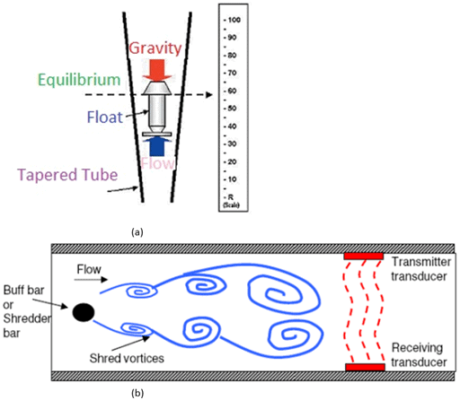 Figure 9.9 Other flow measuring devices: (a) rotameter, and (b) vortex flow meter.
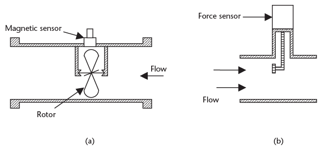 Figure 9.10 Flow rate measuring devices: (a) turbine, and (b) pressure flow meter.
magnetic field is generated across the pipe perpendicular to the electrodes, as shown in Figure 9.11. The conducting fluid flowing through the magnetic field generates a voltage between the electrodes, which can be measured to give the rate of flow. The meter gives an accurate linear output voltage with flow rate. There is no insertion loss, and the readings are independent of the fluid characteristics, but it is a relatively expensive instrument [4].
➢ Ultrasonic flow meters can be transit-time flow meters, or can use the Doppler effect. In the transit-time flow meter, two transducers with receivers are mounted diametrically opposite to each other, but inclined at 45° to the axis of the pipe, as shown in Figure 9.12. Each transducer transmits an ultrasonic beam at a frequency of approximately 1 MHz, which is produced by a piezoelectric crystal. The transit time of each beam is different due to the liquid flow. The difference in transit time of the two beams is used to calculate the average liquid velocity. The advantage of this type of sensor is that the effects of temperature density changes cancel in the two beams. There is no obstruction to fluid flow, and corrosive or varying flow rates are not a problem, but the measurements can be affected by the Reynolds number or velocity profile. The transmitters can be in contact with the liquid, or can be clamped externally on to the pipe.
The Doppler flow meter measures the velocity of entrapped gas (>30μ)or small particles in the liquid, as shown in Figure 9.13. A single transducer and receiver are mounted at 45° to the axis of the pipe. The receiver measures the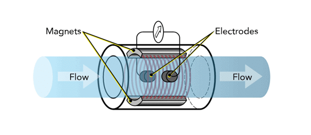 Figure 9.11 Magnetic flow meter.
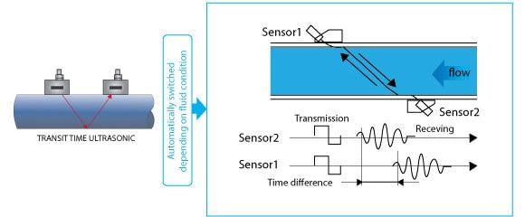 Figure 9.12 Ultrasonic transit-time flow meter.
difference in frequency of the transmitted and received signals, from which the flow velocity can be calculated. The meter can be mounted externally, and is not affected by changes in liquid viscosity.
➢ Ultrasonic flow meters are normally used to measure flow rates in large diameter, nonporous pipes (e.g., cast iron, cement, or fiberglass), and they require periodic recalibration. Meters must not be closer than 10m to each other to prevent interference. This type of meter has a temperature operating range of −20° to +250°C and an accuracy of ±5% FSD.
|
26 videos|28 docs|29 tests
|


