Q1: The number of junctions in the circuit is (2024)
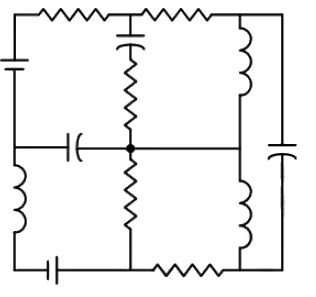 (a) 6
(a) 6
(b) 7
(c) 8
(d) 9
Ans: (a)
Sol:
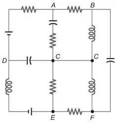 A point at which more than two elements are joints together is called Junction.
A, B, C, D, E and F are junction.
Q2: For the circuit shown in the figure, V1 = 8 V, DC and I1 = 8A, DC. The voltage Vab in Volts is ___ (Round off to 1 decimal place). (2023)

(a) 4.2
(b) 6
(c) 8
(d) 10.6
Ans: (b)
Sol: Reraw the circuit:
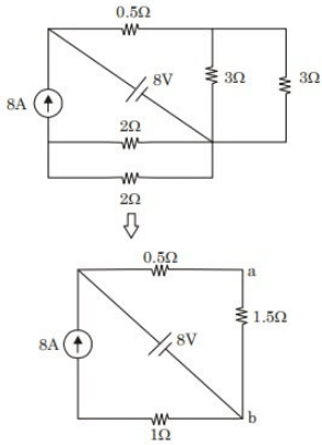 Now, using voltage division,

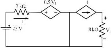
Q3: In the circuit shown below, the magnitude of the voltage V1 in volts, across the 8kΩ resistor is ______________. (round off to nearest integer) (2022)
 (a) 100
(b) 120
(c) 150
(d) 175
Ans: (a)
Sol: Apply kVL :

Q4: In the given circuit, the value of capacitor C that makes current I = 0 is _________ μF. (2021)
 (a) 15
(b) 50
(c) 5
(d) 20
Ans: (d)
Sol: 


 ⇒
⇒ 
⇒ Xc = 10Ω

⇒ 

Q5: The current I flowing in the circuit shown below in amperes (round off to one decimal place) is ____ (2019)
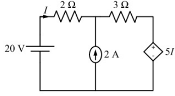 (a) 0.8
(b) 1.1
(c) 1.4
(d) 1.9
Ans: (c)
Sol: 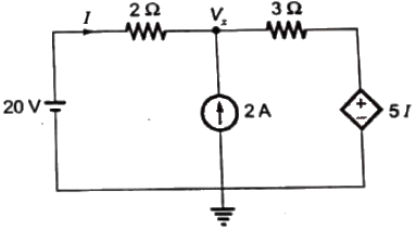 Applying nodal at node x,
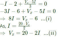 Substituting (ii) in (i),

Q6: The equivalent impedance Zeq for the infinite ladder circuit shown in the figure is (2018)

(a) j12Ω
(b) -j12 Ω
(c) j13 Ω
(d) 13 Ω
Ans: (a)
Sol:


 By solving above equation,
Zeq = j12
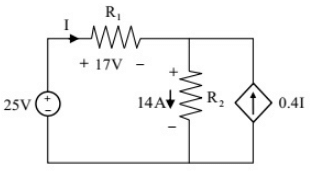
Q7: The power supplied by the 25 V source in the figure shown below is ________W. (SET-1 (2017))
 (a) 25
(b) 250
(c) 2.5
(d) 100
Ans: (b)
Sol: Using KCL at node , we get
I + 0.4I = 14
I = 10A
Now, power supplied,
P = 25×10 = 250W
Q8: The equivalent resistance between the terminals A and B is ______ Ω. (SET-1 (2017))
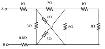 (a) 2.2
(b) 1.2
(c) 1
(d) 3
Ans: (d)
Sol: Consider the following circuit diagram,
 After rearrangement we get
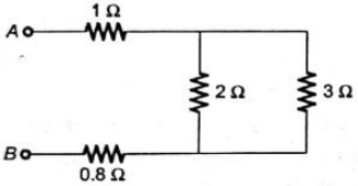 Now,
Now, 
Q9: In the circuit shown below, the voltage and current sources are ideal. The voltage (Vout) across the current source, in volts, is (SET-2 (2016))
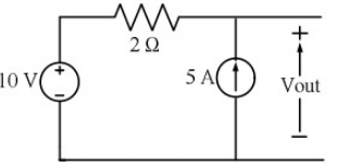 (a) 0
(a) 0
(b) 5
(c) 10
(d) 20
Ans: (d)
Sol: 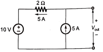 So, Vout = (5 x 2) + 10 = 20V
Q10: In the circuit shown below, the node voltage In the circuit shown below, the node voltage VA is ___________ V. (SET-1 (2016))
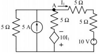 (a) 11.42
(b) 5.55
(c) 7.25
(d) 15.25
Ans: (a)
Sol: 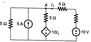 Applying KCL at node A, we get

Q11: In the given circuit, the current supplied by the battery, in ampere, is _______. (SET-1(2016))
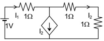 (a) 0.1
(b) 0.5
(c) 1
(d) 1.5
Ans: (b)
Sol:
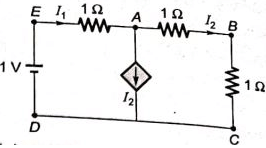 Applying KCL at node A,
 and applying KVL in loop ABCD,
 From equation (i) and (ii),

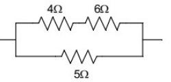
Q12: In the portion of a circuit shown, if the heat generated in 5 Ω resistance is 10 calories per second, then heat generated by the 4 Ω resistance, in calories per second, is _______. (SET-1 (2016))
 (a) 1
(a) 1
(b) 2
(c) 3
(d) 4
Ans: (b)
Sol: 

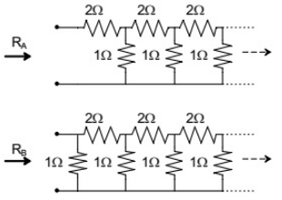
Q13: RA and RB are the input resistances of circuits as shown below. The circuits extend infinitely in the direction shown. Which one of the following statements is TRUE? (SET-1 (2016))
 (a) RA = RB
(b) RA = RB = 0
(c) RA < RB
(d) RB = RA/(1+RA)
Ans: (d)
Sol: If the equavalent resistance of first figure is RA then from the second figure, we can see that RB = RA∣∣1Ω.

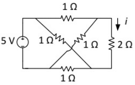
Q14: The current i (in Ampere) in the 2Ω resistor of the given network is ______. (SET-2 (2015))
 (a) 0
(a) 0
(b) 1
(c) 2
(d) 4
Ans: (a)
Sol: Redrawing the circuit,
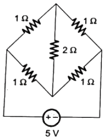 Bridge is balance, so current flowing through 2Ω resistor is 0A.
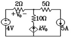
Q15: In the given circuit, the parameter k is positive, and the power dissipated in the 2 Ω resistor is 12.5W. The value of k is _________. (SET-1(2015))
 (a) 0.25
(b) 0.50
(c) 0.72
(d) 0.9
Ans: (b)
Sol: 

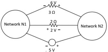
Q16: The voltages developed across the 3 Ω and 2 Ω resistors shown in the figure are 6 V and 2V respectively, with the polarity as marked. What is the power (in Watt) delivered by the 5V voltage source? (SET-1(2015))
 (a) 5
(a) 5
(b) 7
(c) 10
(d) 14
Ans: (a)
Sol:
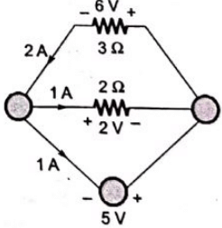 Power = 5 x 1 = 5 Watt
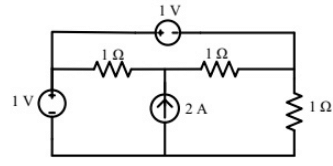
Q17: The power delivered by the current source, in the figure, is ____. (SET-3 (2014))
 (a) 1
(a) 1
(b) 2
(c) 3
(d) 4
Ans: (c)
Sol: 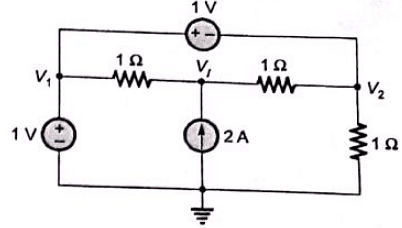 Applying nodal analysis at node P, we have

 ∴ Power delivered by the current source

Q18: In the figure, the value of resistor R is (25 + I/2) ohms, where I is the current in amperes. The current I is _____. (SET-1 (2014))
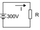 (a) 25
(b) 15
(c) 12
(d) 10
Ans: (d)
Sol: 
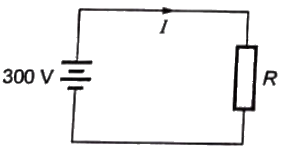 Applying KVL in given loop, we have
300 = IR
300 = (2R − 50) × R
we get, R = 30Ω or −5Ω
Since, resistance can't be negative. therefore,
R = 30Ω

Q19: An incandescent lamp is marked 40 W, 240 V. If resistance at room temperature (26°C) is 120 Ω, and temperature coefficient of resistance is 4.5 × 10⁻³/°C, then its 'ON' state filament temperature in °C is approximately_____. (SET-1 (2014))
(a) 1220.24
(b) 1860.36
(c) 2470.44
(d) 2960.96
Ans: (c)
Sol: Let the resistance of incandescent lamp
 Let, RT be the resistance of the filament in ON state at temperature T.
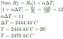 Therefore, ON state temperature of filament = 2470.44°C
Q20: The three circuit elements shown in the figure are part of an electric circuit. The total power absorbed by the three circuit elements in watts is _____. (SET-1 (2014))
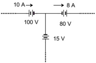 (a) 110
(b) 250
(c) 330
(d) 360
Ans: (c)
Sol: Given electrical circuit is shown below:
Applying KCL at node, current through 15V voltage source = 2 A
Power absorbed by 100 V voltage source = 10x100 = 1000 Watt.
Power absorbed by 80 V voltage source =-(80x8) = -640 Watts and power absorbed by 15 V voltage source = -(15x2) = -30 Watt.
Therefore, total power absorbed by the three circuit element = (100-640-30_ watts = 330 Watts
Q21: Three capacitors C1, C2 and C3 whose values are 10μF, 5μF, and 2μF respectively, have breakdown voltages of 10 V, 5 V and 2 V respectively. For the interconnection shown below, the maximum safe voltage in Volts that can be applied across the combination, and the corresponding total charge in μC stored in the effective capacitance across the terminals are respectively, (2013)
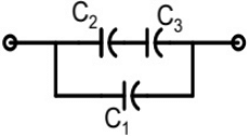 (a) 2.8 and 36
(b) 7 and 119
(c) 2.8 and 32
(d) 7 and 80
Ans: (c)
Sol:  Capacitor C2 and C3 are in series.
In series charge is same.
So, maximum charge on C2 and C3 will be minimum of
 In series the equivalent capacitance of C2 and C3 is
 In parallel, the voltage is same.
V1 = V23 = 2.8V
Change in capacitor C1
 In parallel, the total charge

Q22: Consider a delta connection of resistors and its equivalent star connection as shown below. If all elements of the delta connection are scaled by a factor k, k > 0, the elements of the corresponding star equivalent will be scaled by a factor of (2013)
 (a) k2
(b) k
(c) 1/k
(d) √k
Ans: (b)
Sol: 
Q23: If VA−VB = 6V then VC−VD is (2012)
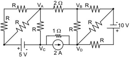 (a) -5V
(b) 2V
(c) 3C
(d) 6V
Ans: (a)
Sol: 

Q24: In the circuit shown below, the current through the inductor is (2012)
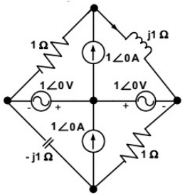 (a)
(a) 
(b)
(c)
(d) 0A
Ans: (c)
Sol:
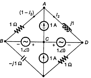 Apply KCL node at 'A'
so, current flowing through 1Ω is (1 − I2)
Applying KVL in ABCD loop,

Q25: If the 12 Ω resistor draws a current of 1 A as shown in the figure, the value of resistance R is (2010)
(a) 4Ω
(b) 6Ω
(c) 8Ω
(d) 18Ω
Ans: (b)
Sol: Assuming voltage of the node Va


Q26: If the electrical circuit of figure (b) is an equivalent of the coupled tank system of figure (a), then (2010)
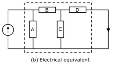 (a) A, B are resistances and C, D capacitances
(b) A, C are resistances and B, D capacitances
(c) A, B are capacitances and C, D resistances
(d) A, C are capacitances and B, D resistances
Ans: (d)
Sol: In such system, volumetric flow rate C is analogous to current and pressure is analogous to voltage
The hydraulic capacitance due to storage in gravity field is defined as
C = A/pg
where, A = Area of the tank
ρ = Density of the fluid
g = Acceleration due to gravity
The hydraulic capacitance is represented by A and C. Liquid trying to flow out of a container,can meet with resistance in several ways. If the outlet is a pipe, the friction between the liquid and the pile wall produces resistance to flow. Such resistance is represented by B and D.
Q27: As shown in the figure, a 1 Ω resistance is connected across a source that has a load line v+i=100. The current through the resistance is (2010)
 (a) 25A
(b) 50A
(c) 100A
(d) 200A
Ans: (b)
Sol: A resistor has linear characteristics
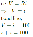 current through resistance,
i = 100/2 = 50A
Q28: For the circuit shown, find out the current flowing through the 2 Ω resistance. Also identify the changes to be made to double the current through the 2 Ω resistance. (2009)
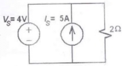 (a) (5 A; Put VS = 30 A)
(b) (2 A; Put VS = 8 A)
(c) (5 A; Put IS = 10 A)
(d) (7 A; Put IS = 12 A)
Ans: (b)
Sol: Voltage across 2Ω resistance = Vs = 4 V
Current through 2Ω resistance 
Current cource has no effect, when connected across voltage source.
So, to double current through 2Ω resistance, voltage source is doubled i.e.
V - s = 8V
Q29: The equivalent capacitance of the input loop of the circuit shown is (2009)
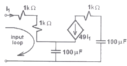 (a) 2 μF
(b) 100 μF
(c) 200 μF
(d) 4 μF
Ans: (a)
Sol: 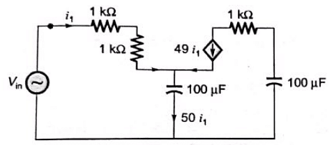 Applying KVL,
 As imaginary part is negative, input impedance has equivalent capacitive reactance XC eq.

Q30: How many 200 W/220 V incandescent lamps connected in series would consume the same total power as a single 100 W/220 V incandescent lamp ? (2009)
(a) not possible
(b) 4
(c) 3
(d) 2
Ans: (d)
Sol: Let resistance of a single incandescent lamp = R.
Power consumed by a single lamp, P = 200W.
When connected across voltage, V = 220V.
 Let, n number of lamps are connected in series across voltage V = 200V.
So total resistance of lamps
Req.= nR = 242n
Total power consumed,

 (a) 6
(a) 6 A point at which more than two elements are joints together is called Junction.
 Now, using voltage division,
 (a) 100
 (a) 15


 ⇒
⇒ 


 (a) 0.8
 Applying nodal at node x,
 Substituting (ii) in (i),


 By solving above equation,
 (a) 25
 (a) 2.2
 After rearrangement we get
 Now,
Now, 
 (a) 0
(a) 0 So, Vout = (5 x 2) + 10 = 20V
 (a) 11.42
 Applying KCL at node A, we get
 (a) 0.1
 Applying KCL at node A,
 and applying KVL in loop ABCD,
 From equation (i) and (ii),
 (a) 1
(a) 1

 (a) RA = RB
 (a) 0
(a) 0 Bridge is balance, so current flowing through 2Ω resistor is 0A.
 (a) 0.25

 (a) 5
(a) 5 Power = 5 x 1 = 5 Watt
 (a) 1
(a) 1 Applying nodal analysis at node P, we have
 ∴ Power delivered by the current source
 (a) 25
 Applying KVL in given loop, we have
 Let, RT be the resistance of the filament in ON state at temperature T.
 Therefore, ON state temperature of filament = 2470.44°C
 (a) 110
 (a) 2.8 and 36
 Capacitor C2 and C3 are in series.
 In series the equivalent capacitance of C2 and C3 is
  In parallel, the voltage is same.
 In parallel, the total charge
 (a) k2
 (a) -5V

 (a)
(a) 


 Apply KCL node at 'A'


 (a) A, B are resistances and C, D capacitances
 (a) 25A
 current through resistance,
 (a) (5 A; Put VS = 30 A)
 (a) 2 μF
 Applying KVL,
 As imaginary part is negative, input impedance has equivalent capacitive reactance XC eq.
 Let, n number of lamps are connected in series across voltage V = 200V.


