Previous Year Questions- Fault Analysis - 2 | Power Systems - Electrical Engineering (EE) PDF Download
Q21: A 2-bus system and corresponding zero sequence network are shown in the figure.
 The transformers T1 and T2 are connected as (SET-1 (2014))
(a) 
(b) 
(c) 
(d) 
Ans: (b)
Sol: We have to use switch diagram for the zero-sequence network of transformer.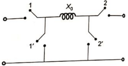 Switch 1 or 2 is closed when winding in Yand neutral grounded.
Switch 1 or 2 is closed when winding is in Δ.
Given, for transformer T1, switch 1 is closed and 2 is open.
Therefore, transformer will be connected in primary with grounded neutral and secondary in star with isolated neutral.
For transformer T2, switch 1 is closed and 2 is closed, therefore, primary winding is star connected with neutral grounded whereas secondary will be delta connected.
Q22: Three-phase to ground fault takes place at locations F1 and F2 in the system shown in the figure. If the fault takes place at location F1, then the voltage and the current at bus A are VF1 and IF1 respectively. If the fault takes place at location F2, then the voltage and the current at bus A and VF2 and IF2 respectively. The correct statement about voltages and currents during faults at F1 and F2 is (SET-1 (2014))
(a) VF1 leads IF1 and VF2 leads IF2
(b) VF1 leads IF1 and VF2 lags IF2
(c) VF1 lags IF1 and VF2 leads IF2
(d) VF1 lags IF1 and VF2 lags IF2
Ans: (c)
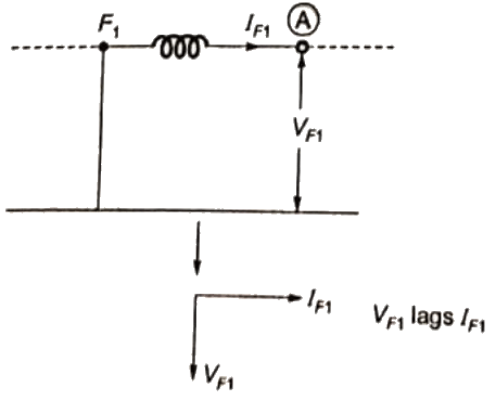
Sol: 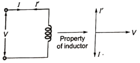 For the fault at location F1 the equivalent circuit is shown below.
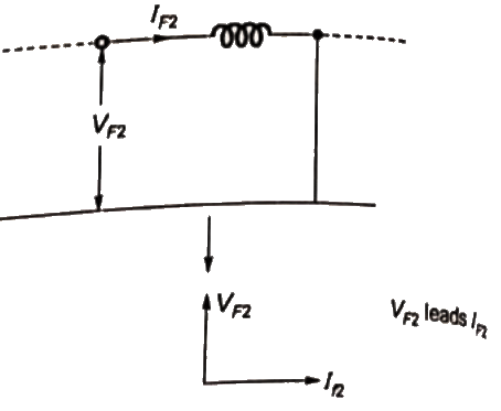
 For the fault at location F2 the equivalent circuit is shown below.
Q23: For a power system network with n nodes, Z33 of its bus impedance matrix is j0.5 per unit. The voltage at node 3 is 1.3 ∠ −10° per unit. If a capacitor having reactance of -j3.5 per unit is now added to the network between node 3 and the reference node, the current drawn by the capacitor per unit is (2013)
(a) 0.325 ∠ −100°
(b) 0.325 ∠80°
(c) 0.371 ∠ −100°
(d) 0.433 ∠80°
Ans: (d)
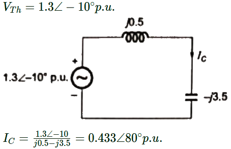
Sol: Thevenin's equivalent circuit between bus (3) and reference bus = Z33 = j0.5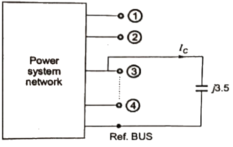 Thevenin's equivalent circuit between 3rd bus (3) and reference
Q24: The sequence components of the fault current are as follows :
Ipositive = j1.5 pu, Inegative = −j0.5, Izero = −j1 pu.
The type of fault in the system is (2012)
(a) LG
(b) LL
(c) LLG
(d) LLLG
Ans: (c)
Sol: Only LLG fault has a unique property that the sum of all sequence components of the fault current is zero.
Q25: Two generator units G1 and G2 are connected by 15 kV line with a bus at the mid-point as shown below G1 = 250 MVA, 15kV, positive sequence reactance X = 25% on its own base
G2 = 100 MVA, 15kV, positive sequence reactance X = 10 % on its own base
L1 and L2 = 10km, positive sequence reactance X = 0.225 Ω/km
In the above system, the three-phase fault MVA at the bus 3 is (2011)
(a) 82.55 MVA
(b) 85.11 MVA
(c) 170.91 MVA
(d) 181.82 MVA
Ans: (d)
Sol: 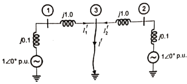
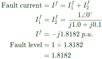
 = 181.82 MV A
Q26: Two generator units G1 and G2 are connected by 15 kV line with a bus at the mid-point as shown below G1 = 250 MVA, 15kV, positive sequence reactance X = 25% on its own base
G2 = 100 MVA, 15kV, positive sequence reactance X = 10 % on its own base
L1 and L2 = 10km, positive sequence reactance X = 0.225 Ω/km
For the above system, the positive sequence diagram with the p.u. values on the 100 MVA common base is (2011)
(a)  (b)
(b)  (c)
(c)  (d)
(d)  Ans: (a)
Sol: 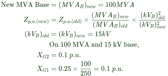 Positive sequence reactance of
Base impedance 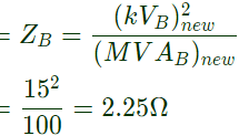
 Hence, option (A) is correct.
Q27: The zero-sequence circuit of the three phase transformer shown in the figure (2010)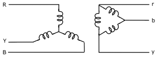 (a)
(a) 
(b) 
(c) 
(d) 
Ans: (c)
Sol: Equivalent circuit for the zero sequence network depends upon the impedances met by the zero sequence currents flowing through the three phases and their sum, 3Ia0, flowing through the neutral impedance and returning through the ground or a neutral conductor.
If there is no complete path for zero sequence currents in a circuit, the zero sequence impedance is infinite.
Thus a Y-connected circuit with ungrounded neutral has infinite impedance to zero sequence currents.
A delta-connected circuit provides no path for zero sequence currents flowing in the line. The zero sequence currents being single phase, circulate within the winding. Hence viewed from its terminals its zero sequence impedance is infinite.
Q28: Consider a power system shown below: Given that: Vs1 = Vs2 = 1 + j0 p.u;
The positive sequence impedance are
Zs1 = Zs2 = 0.001 + j0.01 p.u and ZL = 0.006 + j0.06 p.u
3-phase Base MVA = 100
voltage base = 400 kV(Line to Line)
Nominal system frequency = 50 Hz.
The reference voltage for phase 'a' is defined as V(t) = Vmcos (ωt).
A symmetrical three phase fault occurs at centre of the line, i.e. point 'F' at time 't0'. The positive sequence impedance from source S1 to point 'F' equals 0.004 + j0.04 p.u. The wave form corresponding to phase 'a' fault current from bus X reveals that decaying d.c. offset current is negative and in magnitude at its maximum initial value, Assume that the negative sequence impedances are equal to postive sequence impedance and the zero sequence impedances are three times positive sequence impedances.
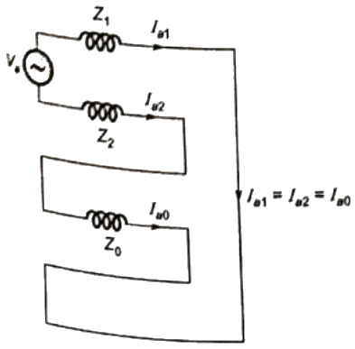
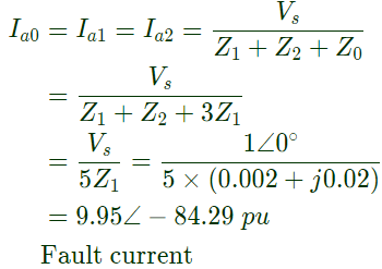
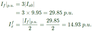
Instead of the three phase fault, if a single line to ground fault occurs on phase 'a' at point 'F' with zero fault impedance, then the rms of the ac component of fault current (Ix) for phase 'a' will be (2008)
(a) 4.97 p.u
(b) 7.0 p.u
(c) 14.93 p.u
(d) 29.85 p.u
Ans: (c)
Sol: 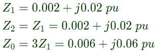
Q29: Consider a power system shown below: Given that: Vs1 = Vs2 = 1 + j0 p.u;
The positive sequence impedance are
Zs1 = Zs2 = 0.001 + j0.01 p.u and ZL = 0.006 + j0.06 p.u
3-phase Base MVA = 100
voltage base = 400 kV(Line to Line)
Nominal system frequency = 50 Hz.
The reference voltage for phase 'a' is defined as V(t) = Vmcos (ωt).
A symmetrical three phase fault occurs at centre of the line, i.e. point 'F' at time 't0'. The positive sequence impedance from source S1 to point 'F' equals 0.004 + j0.04 p.u. The wave form corresponding to phase 'a' fault current from bus X reveals that decaying d.c. offset current is negative and in magnitude at its maximum initial value, Assume that the negative sequence impedances are equal to postive sequence impedance and the zero sequence impedances are three times positive sequence impedances.
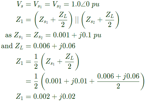
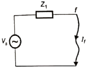
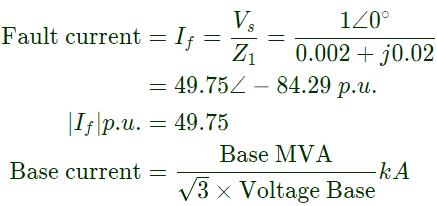
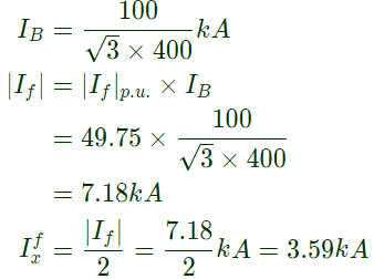
The rms value of the component of fault current (Ix) will be (2008)
(a) 3.59 kA
(b) 5.07 kA
(c) 7.18 kA
(d) 10.15 kA
Ans: (a)
Sol: Fault occurs at mid point 'F'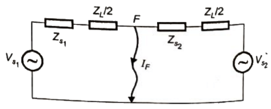 Thevenins equivalent,
Q30: Consider a power system shown below: Given that: Vs1 = Vs2 = 1 + j0 p.u;
The positive sequence impedance are
Zs1 = Zs2 = 0.001 + j0.01 p.u and ZL = 0.006 + j0.06 p.u
3-phase Base MVA = 100
voltage base = 400 kV(Line to Line)
Nominal system frequency = 50 Hz.
The reference voltage for phase 'a' is defined as V(t) = Vmcos (ωt).
A symmetrical three phase fault occurs at centre of the line, i.e. point 'F' at time 't0'. The positive sequence impedance from source S1 to point 'F' equals 0.004 + j0.04 p.u. The wave form corresponding to phase 'a' fault current from bus X reveals that decaying d.c. offset current is negative and in magnitude at its maximum initial value, Assume that the negative sequence impedances are equal to postive sequence impedance and the zero sequence impedances are three times positive sequence impedances.
The instant (t0) of the fault will be (2008)
(a) 4.682 ms
(b) 9.667 ms
(c) 14.667 ms
(d) 19.667 ms
Ans: (a)
Sol: 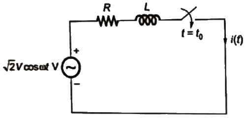 To find i(t) and t(0+) we can convert the above circuit in following way
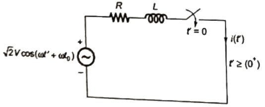
 Symmetrical short circuit current,
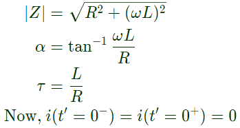

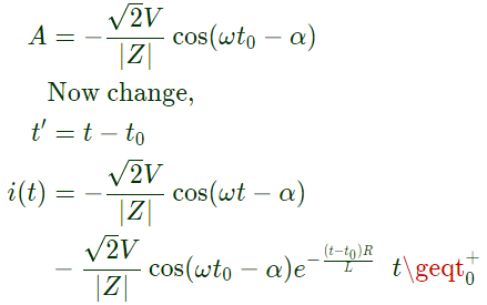 Now, if the initial value of dc of set (A) is
it requires that cos (ωt0 − α) = 1  In problem given the circuit for 3 − ϕ fault be drawn as:
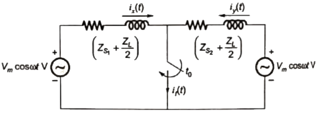
According to the derrivation
For initial value of dc off set to be 

Q31: A-3-phase transmission line is shown in figure :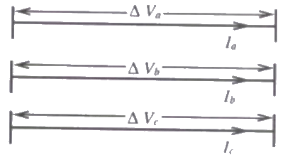 Voltage drop across the transmission line is given by the following equation :
 Shunt capacitance of the line can be neglect. If the has positive sequence impedance of 15 Ω and zero sequence impedance of 48 Ω, then the values of Zs and Zm will be (2008)
(a) Zs = 31.5Ω; Zm = 16.5Ω
(b) Zs = 26Ω; Zm = 11Ω
(c) Zs = 16.5Ω; Zm = 31.5Ω
(d) Zs = 11Ω; Zm = 26Ω
Ans: (b)
Sol: Positive sequence impedance = Negative sequence impedance
= Zs − Zm = 15...(i)
Zero-sequence impedance = Zs + 2Zm = 48...(ii)
Solving equation (i) and (ii), we get,
Zs = 26Ω and Zm = 11Ω
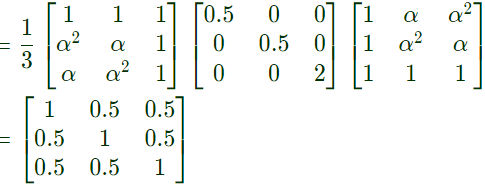
Q32: Suppose we define a sequence transformation between "a - b - c" and "p - n - o" variables as follows: (2007) where
where  and k and is a constant.
Now, if it is given that : 
 (a)
(a) 
(b) 
(c) 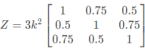
(d) 
Ans: (b)
Sol: Here, where,
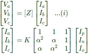
 similarly,
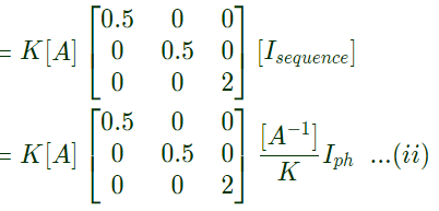 comparing eq. (i) with (ii),
Q33: A three phase balanced star connected voltage source with frequency ω rad/s is connected to a star connected balanced load which is purely inductive. The instantaneous line currents and phase to neutral voltages are denoted by (ia, ib, ic) and (van, vbn, vcn) respectively, and their rms values are denoted by V and I.
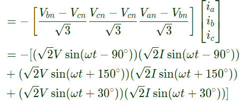
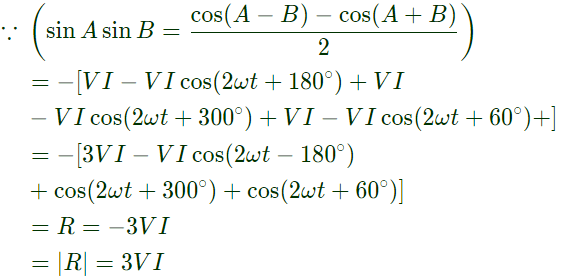
If  then the magnitude of R is (2007)
(a) 3VI
(b) VI
(c) 0.7VI
(d) 0
Ans: (a)
Sol:  Assuming phase sequence abc, taking Van as the reference,
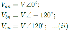 V is the rms value of Van, Vbn and Vcn
I is the rms value of ia, ib and ic
From equation (ii), we can say  and similarly due to lagging load
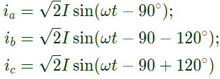 From equation (iii) by considering line values of voltage
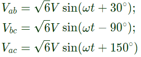 From equation (i), we have
Q34: Three identical star connected resistors of 1.0 pu are connected to an unbalanced 3-phase supply. The load neutral is isolated. The symmetrical components of the line voltages in pu. are:
Vab1 = X∠θ1, Vab2 = Y∠θ2.
If all the pu calculations are with the respective base values, the phase to neutral sequence voltages are (2006)
(a) Van1 = X∠(θ1 + 30°), Van2 = Y(θ2 − 30°)
(b) Van1 = X∠(θ1 − 30°), Van2 = Y(θ2 + 30°)
(c) 
(d) 
Ans: (b)
Sol: Positive (negative ) sequence component of line voltage is √3 time of positive (negative) sequence component of phase voltage and leads (lags) by 30° in actual value but in p.u. on respective base value they are equal.,
Q35: At a 220 kV substation of a power system, it is given that the three-phase fault level is 4000 MVA and single-line to ground fault level is 5000 MVA Neglecting the resistance and the shunt suspectances of the system.
The zero sequence driving point reactance at the bus is (2005)
(a) 2.2 Ω
(b) 4.84 Ω
(c) 18.18 Ω
(d) 22.72 Ω
Ans: (b)
Sol: Let negative sequence reactance = X2
Assuming, X2 = X1
and zero sequence reactance = X0
In single-line to ground fault,
 In SLG fault
Positive sequence current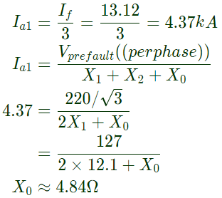
Q36: At a 220 kV substation of a power system, it is given that the three-phase fault level is 4000 MVA and single-line to ground fault level is 5000 MVA Neglecting the resistance and the shunt suspectances of the system.
The positive sequence driving point reactance at the bus is (2005)
(a) 2.5 Ω
(b) 4.033 Ω
(c) 5.5 Ω
(d) 12.1 Ω
Ans: (d)
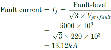
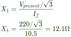
Sol: Fault level (in MVA) = √3 × prefault line voltage (kV) × fault current (in kA)
Pre-fault line voltage = Vprefault = 220kV
3 − ϕ fault level = 4000 MVA
 Let positive sequence driving point reactance = X1
Q37: The parameters of a transposed overhead transmission line are given as :
Self reactance Xs = 0.5Ω/km and Mutual reactance Xm = 0.1Ω/km
The positive sequence reactance X1 and zero sequence reactance X0, respectively in Ω/km are (2005)
(a) 0.3, 0.2
(b) 0.5, 0.2
(c) 0.5, 0.6
(d) 0.3, 0.6
Ans: (d)
Sol: For transmission line
Positive sequence impedance,
X1 = Xs − Xm = 0.4 − 0.1 = 0.3Ω/km
Zero sequence impedance,
X0 = Xs + 2Xm = 0.4 + 0.2 = 0.6Ω/km
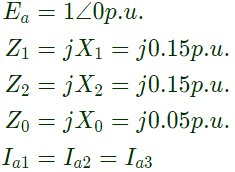
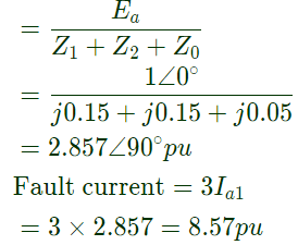
Q38: A 500 MVA, 50 Hz, 3-phase turbo-generator produces power at 22 kV. Generator is Y-connected and its neutral is solidly grounded. It sequence reactances are X1 = X2 = 0.15 pu and X0 = 0.05 pu.It is operating at rated voltage and disconnected from the rest of the system (no load). The magnitude of the sub-transient line current for single line to ground fault at the generator terminal in pu will be (2004)
(a) 2.851
(b) 3.333
(c) 6.667
(d) 8.553
Ans: (d)
Sol: For single-line to ground fault,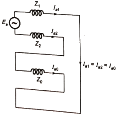 Since, the generator is operating at no-load and rated voltage
Q39: A 3-phase transmission line supplies Δ-connected load Z. The conductor 'c' of the line develops an open circuit fault as shown in figure. The currents in the lines are as shown on the diagram. The positive sequence current component in line 'a' will be (2004)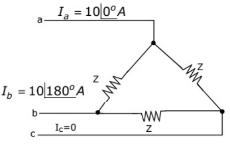 (a) 5.78∠ − 30°
(b) 5.78 ∠ 90°
(c) 6.33 ∠ 90°
(d) 10.0 ∠ −30°
Ans: (a)
Sol: 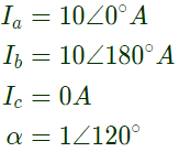 Positive sequence current component in line 'a'
Q40: A 3-phase generator rated at 110 MVA, 11 kV is connected through circuit breakers to a transformer. The generator is having direct axis sub-transient reactance  transient reactance
  and synchronous reactance = 130%. The generator is operating at no load and rated voltage when a three phase short circuit fault occurs between the breakers and the transformer. The magnitude of initial symmetrical rms current in the breakers will be (2004)(a) 4.44 kA
(b) 22.20 kA
(c) 30.39 kA
(d) 38.45 kA
Ans: (c)
Sol: The generator is operating at no-load and rated voltage
So, Eg = 1.0∠0°p.u.
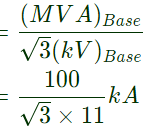
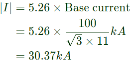
Initial symmetrical current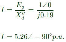 Base current
Q41: Three-phase alternator generating unbalanced voltages is connected to an unbalanced load through a 3-phase transmission line as shown in figure. The neutral of the alternator and the star point of the load are solidly grounded. The phase voltages of the alternator are Ea = 10∠0°V, Eb = 10∠−90°V, Ec = 10∠120°V. The positive sequence component of the load current is (2003) (a) 1.310∠ − 107°A
(b) 0.332∠ − 120°A
(c) 0.996∠ − 120°A
(d) 3.510∠ − 81°A
Ans: (d)
Sol: Since both sides are grounded, we can take it as 3 independent circuit.
Hence,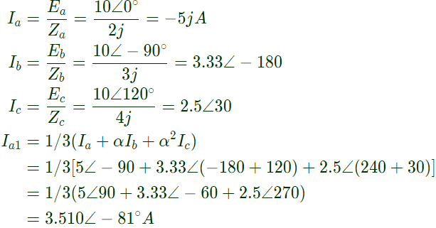
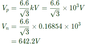
Q42: A 20-MVA, 6.6-kV, 3-phase alternator is connected to a 3-phase transmission line. The per unit positive sequence, negative sequence and zero sequence impedances of the alternator are j0.1, j0.1 and j0.04 respectively. The neutral of the alternator is connected to ground through an inductive reactor of j0.05 p.u. The per unit positive, negative and zero sequence impedances of transmission line are j0.1, j0.1 and j0.3, respectively. All per unit values are based on the machine ratings. A solid ground fault occurs at one phase of the far end of the transmission line. The voltage of the alternator neutral with respect to ground during the fault is (2003)
(a) 513.8 V
(b) 889.9 V
(c) 1112.0 V
(d) 642.2 V
Ans: (d)
Sol: For alternator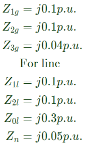 Equivalent sequence impedance:
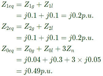 For single line to ground fault
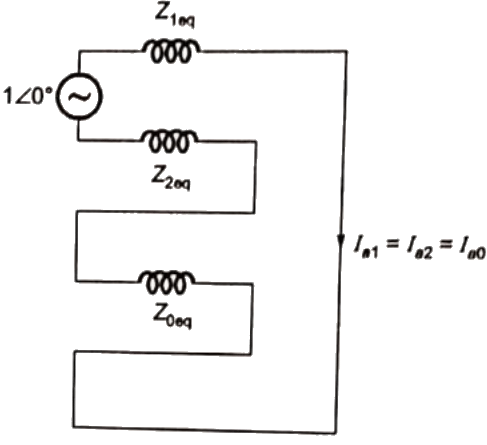
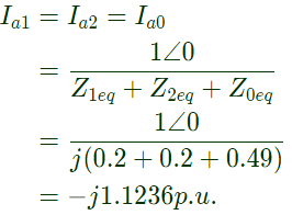 Fault current = If = 3Ia1 = −j3.3708p.u.
Voltage of neutral w.r.t. ground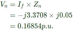 Per phase base voltage
Q43: A generator is connected to a transformer which feeds another transformer through a short feeder(as shown in figure). The zero sequence impedance values are expressed in pu on a common base and are indicated in figure. The Thevenin equivalent zero sequence impedance at point B is (2002)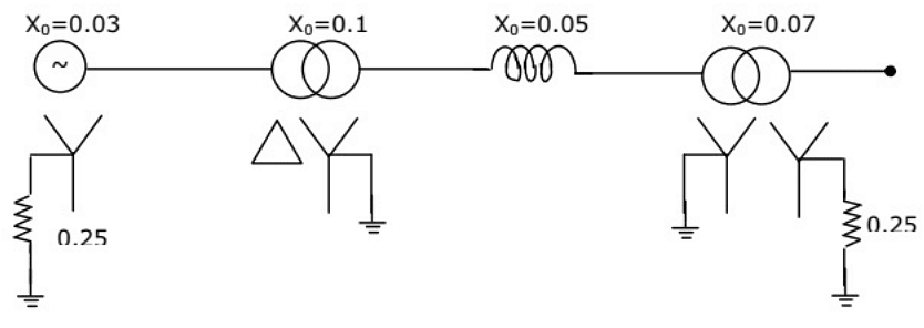 (a) 0.8 + j0.6
(b) 0.75 + j0.22
(c) 0.75 + j0.25
(d) 1.5 + j0.25
Ans: (b)
Sol: 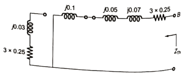 ZTh = 0.75 + j0.22
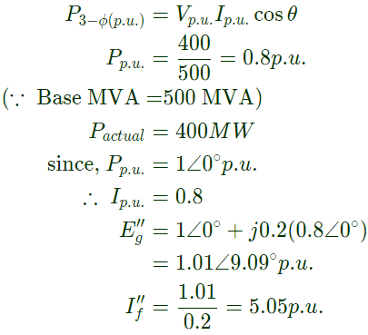
Q44: A 50 Hz alternator is rated 500 MVA, 20 kV, with Xd = 1.0 per unit and  per unit. It supplies a purely resistive load of 400 MW at 20 kV. The load is connected directly across the generator terminals when a symmetrical fault occurs at the load terminals. The initial rms current in the generator in per unit is (2001)(a) 7.22
(b) 6.4
(c) 3.22
(d) 2.2
Ans: (b)
Sol: 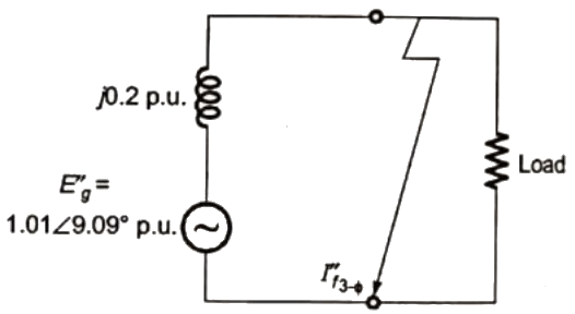
|
30 videos|101 docs|45 tests
|
FAQs on Previous Year Questions- Fault Analysis - 2 - Power Systems - Electrical Engineering (EE)
| 1. What is fault analysis in electrical engineering? |  |
| 2. What are the common types of faults in electrical systems? |  |
| 3. How is fault analysis carried out in electrical systems? |  |
| 4. Why is fault analysis important in electrical engineering? |  |
| 5. What are the consequences of neglecting fault analysis in electrical systems? |  |


