Electrical Engineering (EE) Exam  >  Electrical Engineering (EE) Notes  >  Electrical and Electronic Measurements  >  Previous Year Questions- Measurement of Resistance and Potentiometers

Previous Year Questions- Measurement of Resistance and Potentiometers | Electrical and Electronic Measurements - Electrical Engineering (EE) PDF Download

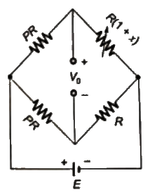
Q1: An unbalanced DC Wheatstone bridge is shown in the figure. At what value of p will the magnitude of Vo be maximum? (SET-1(2015))
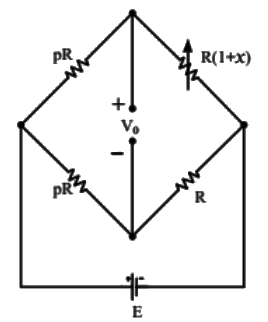
Previous Year Questions- Measurement of Resistance and Potentiometers | Electrical and Electronic Measurements - Electrical Engineering (EE)(a) Previous Year Questions- Measurement of Resistance and Potentiometers | Electrical and Electronic Measurements - Electrical Engineering (EE)

(b) (1 + x)
(c) Previous Year Questions- Measurement of Resistance and Potentiometers | Electrical and Electronic Measurements - Electrical Engineering (EE)

(d) Previous Year Questions- Measurement of Resistance and Potentiometers | Electrical and Electronic Measurements - Electrical Engineering (EE)
Ans: (a)
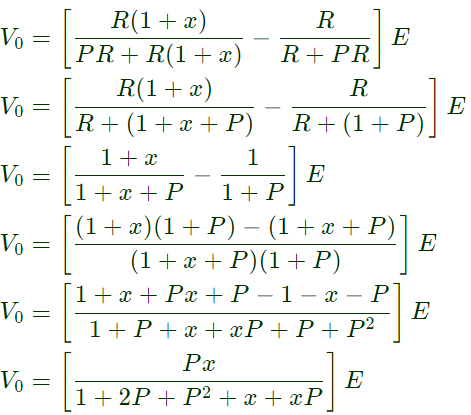
Sol: Previous Year Questions- Measurement of Resistance and Potentiometers | Electrical and Electronic Measurements - Electrical Engineering (EE)Previous Year Questions- Measurement of Resistance and Potentiometers | Electrical and Electronic Measurements - Electrical Engineering (EE)For maximum V0,
dV0/dP = 0  
Previous Year Questions- Measurement of Resistance and Potentiometers | Electrical and Electronic Measurements - Electrical Engineering (EE)⇒ [1 + x + P(2+P+x)] = P(2P+x+2)
⇒ 1 + x + 2P + P2 + Px = 2p2 + Px + 2P
⇒ 1 + x = P2
⇒ P = Previous Year Questions- Measurement of Resistance and Potentiometers | Electrical and Electronic Measurements - Electrical Engineering (EE)
Q2: Suppose that resistors R1 and R2 are connected in parallel to give an equivalent resistor R. If resistors R1 and R2 have tolerance of 1% each, the equivalent resistor R for resistors R1 = 300Ω and R2 = 200Ω will have tolerance of   (SET-2 (2014))
(a) 0.50%
(b) 1%
(c) 1.20%
(d) 2%
Ans:
(b)
Sol: Given, R1=300Ω,  R2=200Ω
Equivalent resistance of parallel combination of R1 and R2
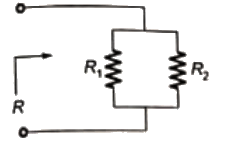
Previous Year Questions- Measurement of Resistance and Potentiometers | Electrical and Electronic Measurements - Electrical Engineering (EE)Previous Year Questions- Measurement of Resistance and Potentiometers | Electrical and Electronic Measurements - Electrical Engineering (EE)

= 120Ω = RT 
Given tolerance of R1 = 1%
∴ R= 300 ± 3
R= 303Ω or 297Ω
Tolerance of R2 = 1%
∴ R2 = 200 ± 2
R2 = 202Ω or 198Ω
Equivalent resistance of the parallel combination of R1 and  R2 in high range is:
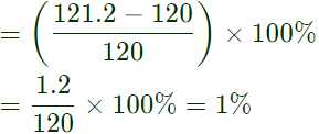
Previous Year Questions- Measurement of Resistance and Potentiometers | Electrical and Electronic Measurements - Electrical Engineering (EE)∴ Tolerance for equivalent resistance R in high range of R1 and R2 is  
Previous Year Questions- Measurement of Resistance and Potentiometers | Electrical and Electronic Measurements - Electrical Engineering (EE)Previous Year Questions- Measurement of Resistance and Potentiometers | Electrical and Electronic Measurements - Electrical Engineering (EE)Note: In low range of R1 and R2,
Previous Year Questions- Measurement of Resistance and Potentiometers | Electrical and Electronic Measurements - Electrical Engineering (EE)∴ Tolerance of equivalent resistance, R in low range is,  
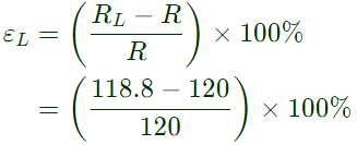
Previous Year Questions- Measurement of Resistance and Potentiometers | Electrical and Electronic Measurements - Electrical Engineering (EE)= -1%

Q3: A strain gauge forms one arm of the bridge shown in the figure below and has a nominal resistance without any load as Rs = 300Ω. Other bridge resistances are R1 = R2 = R3 = 300Ω. The maximum permissible current through the strain gauge is 20 mA. During certain measurement when the bridge is excited by maximum permissible voltage and the strain gauge resistance is increased by 1% over the nominal value, the output voltage V0 in mV is (2013)
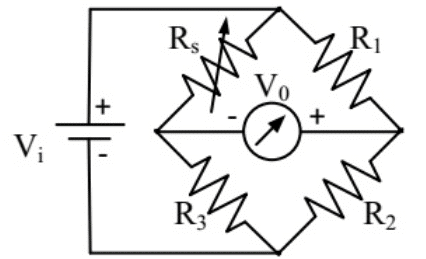
Previous Year Questions- Measurement of Resistance and Potentiometers | Electrical and Electronic Measurements - Electrical Engineering (EE)(a) 56.02
(b) 40.83
(c) 29.85
(d) 10.02
Ans: 
(c)
Sol: Previous Year Questions- Measurement of Resistance and Potentiometers | Electrical and Electronic Measurements - Electrical Engineering (EE)Vab = V− Vb
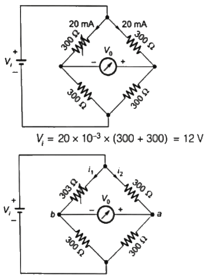
Using voltage division rule,
Previous Year Questions- Measurement of Resistance and Potentiometers | Electrical and Electronic Measurements - Electrical Engineering (EE)= 29.85mV

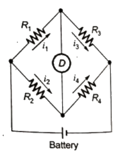
Q4: R1 and R4 are the opposite arms of a Wheatstone bridge as are R3 and R2. The source voltage is applied across R1 and R3. Under balanced conditions which one of the following is true  (2006)
(a) R1 = R3R4/R2
(b) R1=R2R3/R4R1 = R2R3/R4
(c) R1=R2R4/R3R1 = R2R4/R3
(d) R1 = R+ R+ R4 
Ans: 
(b)
Sol: Previous Year Questions- Measurement of Resistance and Potentiometers | Electrical and Electronic Measurements - Electrical Engineering (EE)Adjustment are made in various arms of the bridge so that the voltage across the detector is zero and hence no current slows through it, when no current flows through detector the bridge is said to be balanced.
Under condition of balance = R1 = R2(R3/R4)

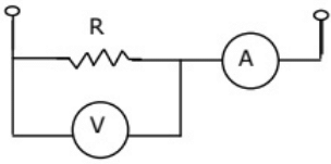
Q5: The set-up in the figure is used to measure resistance R. The ammeter and voltmeter resistances are 0.01 Ω and 2000 Ω, respectively. Their readings are 2A and 180V, respectively, giving a measured resistances of 90 Ω. The percentage error in the measurement is (2005)
Previous Year Questions- Measurement of Resistance and Potentiometers | Electrical and Electronic Measurements - Electrical Engineering (EE)(a) 2.25%
(b) 2.35%
(c) 4.50%
(d) 4.71%
Ans:
(c)
Sol: Measured value of resistance = 90Ω
Resistance of voltmeter, Rv = 2000Ω
Voltage across voltmeter,  V = 180
Current through voltmeter = V/Rv = 180/2000 = 0.09 A
Current through resistance,
(R) = IR = 2 − Iv = 2 − 0.09
⇒ IR = 1.91A
True value of resistance,
Previous Year Questions- Measurement of Resistance and Potentiometers | Electrical and Electronic Measurements - Electrical Engineering (EE)Previous Year Questions- Measurement of Resistance and Potentiometers | Electrical and Electronic Measurements - Electrical Engineering (EE)
Q6: A dc potentiometer is designed to measure up to about 2 V with a slide wire of 300 mm. A standard cell of emf 1.18 V obtains balance at 600 mm. A test cell is seen to obtain balance at 680 mm. The emf of the test cell is (2004)
(a) 1.00 V
(b) 1.34 V
(c) 1.50 V
(d) 1.70 V
Ans:
(b)
Sol: E1= standerd call of emf 1.18
l1 = 600 mm
E2 = emf of the test cell
i2 = 680 mm
The voltage of any point along the slide wire is proportional to length of slide wire.
E ∝ l
Previous Year Questions- Measurement of Resistance and Potentiometers | Electrical and Electronic Measurements - Electrical Engineering (EE)= (680/600) x 1.18 = 1.34 V

The document Previous Year Questions- Measurement of Resistance and Potentiometers | Electrical and Electronic Measurements - Electrical Engineering (EE) is a part of the Electrical Engineering (EE) Course Electrical and Electronic Measurements.
All you need of Electrical Engineering (EE) at this link: Electrical Engineering (EE)
3 videos|39 docs|22 tests

Top Courses for Electrical Engineering (EE)

3 videos|39 docs|22 tests
Download as PDF
Explore Courses for Electrical Engineering (EE) exam

Top Courses for Electrical Engineering (EE)

Signup for Free!
Signup to see your scores go up within 7 days! Learn & Practice with 1000+ FREE Notes, Videos & Tests.
10M+ students study on EduRev
Related Searches

Viva Questions

,

practice quizzes

,

Important questions

,

study material

,

Free

,

Summary

,

video lectures

,

Previous Year Questions- Measurement of Resistance and Potentiometers | Electrical and Electronic Measurements - Electrical Engineering (EE)

,

Semester Notes

,

Previous Year Questions- Measurement of Resistance and Potentiometers | Electrical and Electronic Measurements - Electrical Engineering (EE)

,

mock tests for examination

,

Extra Questions

,

shortcuts and tricks

,

past year papers

,

ppt

,

MCQs

,

Objective type Questions

,

Previous Year Questions with Solutions

,

Exam

,

pdf

,

Previous Year Questions- Measurement of Resistance and Potentiometers | Electrical and Electronic Measurements - Electrical Engineering (EE)

,

Sample Paper

;