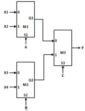
Q1: Consider a digital logic circuit consisting of three 2-to-1 multiplexers M1, M2, and M3 as shown below. X1 and X2 are inputs of M1. X3 and X4 are inputs of M2. A, B, and C are select lines of M1, M2, and M3, respectively. (2024 SET-1)
 For an instance of inputs XXI = X2 = 1, X3 = 0, and X4 = 0, the number of combinations of A, B, C that give the output Y = 1 is _______
(a) 2
(b) 4
(c) 5
(d) 6
Ans: (b)
Sol:
 As we know that the output equations of any 2 x 1 multiplexer is Yout =
where A is the selection line and I0, I1 act as input to the multiplexer.
The output of the first multiplexer: Q1 =
Similarly the output of the second multiplexer: Q2 =
Now this output is act as input to the third multiplexer. so output equations is:

As we know with the three inputs total eight combinations are possible, since output Y is independent from A, B and dependent on C.
it gives output as logic one when C = 0
so the correct combinations are as follows:

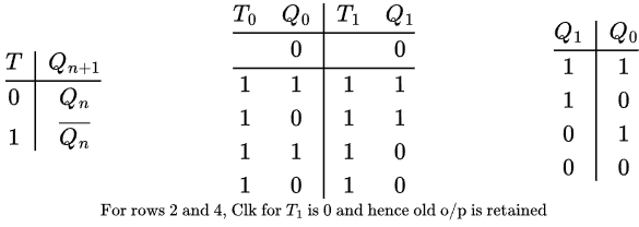
Q2: Consider a sequential digital circuit consisting of T flip-flops and D flip-flops as shown in the figure. CLKIN is the clock input to the circuit. At the beginning, Q1, Q2 and Q3 have values 0, 1 and 1, respectively.
 Which one of the given values of (Q1, Q2, Q3) can NEVER be obtained with this digital circuit? (2023)
(a) (0, 0, 1)
(b) (1, 0, 0)
(c) (1, 0, 1)
(d) (1, 1, 1)
Ans: (a)
Sol:
From the given 3 state counter made from T flipflops and D flipflops, the next input sequence are as follows:


we can see from the above table given counter count sequence like
011 → 000 → 100 → 010 → 101 → 111 → 110. The state 001 is missing.
Option (A) is correct.
Q3: Consider a 3-bit counter, designed using T flip-flops, as shown below:
 Assuming the initial state of the counter given by PQR as 000, what are the next three states? (2021 SET-1)
(a) 011, 101, 000
(b) 001, 010, 111
(c) 011, 101, 111
(d) 001, 010, 000
Ans: (a)
Sol:
From the given 3 state counter made from T flipflops, the next input sequence are as follows:

 In T flip flop for low input (0), the next state is Qn (current state) and for high input (1), it toggles/complements the present state
011, 101, 000
Option A is correct.
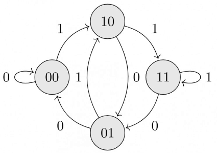
Q4: Consider the sequential circuit shown in the figure, where both flip-flops used are positive edge-triggered D flip-flops.
 The number of states in the state transition diagram of this circuit that have a transition back to the same state on some value of "in" is _______. (2018)
(a) 1
(b) 2
(c) 3
(d) 4
Ans: (b)
Sol:
 Here 00 on input 0 and 11 on input 1 have transition back to itself. So, answer is 2.
Q5: The next state table of a 2-bit saturating up-counter is given below. (2017 SET-2)

The counter is built as a synchronous sequential circuit using T flip-flops. The expression for T1 and T0 are
(a)
(b)
(c)
(d)
Ans: (b)
Sol:

By using above excitation table,
T1 = Q1' Q0,
T2 = (Q1 Q0)' = Q1' + Q0'
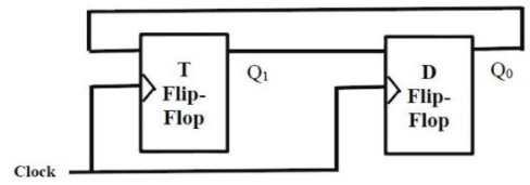
Q6: Consider a combination of T and D flip-flops connected as shown below. The output of the D flip-flop is connected to the input of the T flip-flop and the output of the T flip-flop is connected to the input of the D flip-flop
 Initailly, both Q0 and Q1 are set to 1 (before the 1st clock cycle). The outputs
(a) Q1 Q0 after 3rd cycle are 11 and after the 4th cycle are 00 respectively
(b) Q1 Q0 after 3rd cycle are 11 and after the 4th cycle are 01 respectively
(c) Q1 Q0 after 3rd cycle are 00 and after the 4th cycle are 11 respectively
(d) Q1 Q0 after 3rd cycle are 01 and after the 4th cycle are 01 respectively
Ans: (b)
Sol:
Since it is synchronous so, after every clock cycle T will toggle if input is 1 and will be in Hold State if input is 0. D flip-flop's output always follows input
- After 1 clock cycles: Q1 = 0 (Toggle) Q0 = 10
- After 2 clock cycles: Q1 = 1 (Toggle) Q0 = 0
- After 3 clock cycles: Q1 = 1 (Hold) Q0 = 1
- After 4 clock cycles: Q1 = 0(Toggle) Q0 = 1
Hence, option (B) is correct.
Q7: We want to design a synchronous counter that counts these quence 0-1-0-2-0-3 and then repeats. The minimum number of J-K flip flop srequired to implement this counter is ________. (2016 SET-1)
(a) 3
(b) 4
(c) 5
(d) 2
Ans: (b)
Sol:
We need four JK flipflops.
0 →1 → 0 → 2 → 0 →3
There are 6 states and 3 of them correspond to same states.
- To differentiate between 0, 1, 2, 3 we need 2 bits.
- To differentiate between 3 0's we need another 2 bits.
So, total 4-bits → 4 FFs
Q8: The minimum number of JK flip-flops required to construct a synchronous counter with the count sequence (0, 0, 1, 1, 2, 2 , 3, 3, 0, 0, ...) is ________. (2015 SET-2)
(a) 2
(b) 3
(c) 4
(d) 5
Ans: (b)
Sol:
First, lets design a counter for 0, 1, 2, 3. It is a MOD - 4 counter. Hence, number of Flip Flops required will be two. Count sequence will be:
00-01 10 11
Count sequence mentioned in question is:
00 → 00 → 01 → 01 → 10 → 10 →11 → 11
Now, two flip flops won't suffice. Since we are confronted with repeated sequence, we may
add another bit to the above sequence:
000 → 100 → 001 → 101 → 010 → 110 → 011 → 111
Now each and every count is unique, occurring only once. Meanwhile, our machine has been
extended to a MOD - 8 counter. Hence, three Flip Flops suffice.
Just neglect the MSB flip flop output and take the o/p of other two only. So, we have :
0, 0, 1, 1, 2, 2, 3, 3, . . .
So, correct answer: 3.
Q9: A positive edge-triggered D flip-flop is connected to a positive edge-triggered JK flip-flop as follows. The Q output of the D flip-flop is connected to both the J and K inputs of the JK flip-flop, while the Q output of the JK flip-flop is connected to the input of the D flip-flop. Initially, the output of the D flip-flop is set to logic one and the output of the JK flip-flop is cleared. Which one of the following is the bit sequence (including the initial state) generated at the Q output of the JK flip-flop when the flip-flops are connected to a free-running common clock? Assume that J=K=1 is the toggle mode and J=K=0 is the state-holding mode of the JK flip-flop. Both the flip-flops have non-zero propagation delays. (2015 SET-1)
(a) 0110110...
(b) 0100100...
(c) 0100100...
(d) 011001100...
Ans: (a)
Sol:
 D flipflop output will be same as its input and JK flipflop output toggles when 1 is given to both J and K inputs.
i.e., Q = Dprev (Qprev') + (Dprev') Qprev
Correct Answer. A
Q10: Consider a 4-bit Johnson counter with an initial value of 0000. The counting sequence of this counter is (2015 SET-1)
(a) 0, 1, 3, 7, 15, 14, 12, 8, 0
(b) 0, 1, 3, 5, 7, 9, 11, 13, 15, 0
(c) 0, 2, 4, 6, 8, 10, 12, 14, 0
(d) 0, 8, 12, 14, 15, 7, 3, 1, 0
Ans: (d)
Sol:
Counting procedure of a Johnson's Counter
1. Starting from all O's, each shift operation inserts 1's from the left until the register is filled with all 1's.
2. When the register has all 1s, each shift operation inserts O's from the left until the register is filled with all 0's.
3. Go to step 1.
0000 → 1000 → 1100 → 1110 → 1111 → 0111 → 0011 → 0001 → 0000
OR
0 → 8 → 12 → 14 → 15 → 7 → 3 → 1→0
∴ Option D is correct answer.
Q11:
 The above synchronous sequential circuit built using JK flip-flops is initialized with Q2Q1Q0 = 000. The state sequence for this circuit for the next 3 clock cycles is (2014 SET-3)
(a) 001, 010, 011
(b) 111, 110, 101
(c) 100, 110, 111
(d) 100, 011, 001
Ans: (c)
Sol:
 Option C
Q12: Let k = 2n. A circuit is built by giving the output of an n-bit binary counter as input to an n-to-2n bit decoder.
This circuit is equivalent to a (2014 SET-2)
(a) k-bit binary up counter
(b) k-bit binary down counter.
(c) k-bit ring counter.
(d) k-bit Johnson counter
Ans: (c)
Sol:
Binary counter of n bits can count up to 2n numbers. When this output from counter is fed as input (n bit) to decoder one out of 2n output lines will be activated. So, this arrangement of counter and decoder is behaving as 2n or k-bit ring counter.
Correct Answer: C
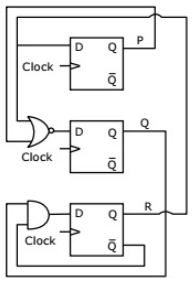
Q13: Consider the following circuit involving three D-type flip-flops used in a certain type of counter configuration.
 If all the flip-flops were reset to 0 at power on, what is the total number of distinct outputs (states) represented by PQR generated by the counter? (2011)
(a) 3
(b) 4
(c) 5
(d) 6
Ans: (b)
Sol:
Characteristic equation of D FF is, Q(t + 1) = D
So, P+ = R, and R+ = Q. R'
Sequence of states will be as:

4 is the number of distinct states.
Correct Answer: B
Q14: Consider the following circuit involving three D-type flip-flops used in a certain type of counter configuration.
 If at some instance prior to the occurrence of the clock edge, P. Q and R have a value 0, 1 and 0 respectively, what shall be the value of PQR after the clock edge? (2011)
(a) 000
(b) 001
(c) 010
(d) 011
Ans: (d)
Sol:
As in D-flip-flop, next output is Q+ = D
- Pi+1 = Ri
- Qi+1 = (Pi + Ri)'
- Ri+1 = R'i Qi
 So, total number of distinct outputs = 4
Q15: The minimum number of D flip-flops needed to design a mod-258 counter is (2011)
(a) 9
(b) 8
(c) 512
(d) 258
Ans: (a)
Sol:
Mod 258 counter has 258 states. We need to find no. of bits to represent 257 at max.
2n ≥ 258 ⇒ n ≥ 9.
Answer is A.
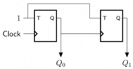
Q16: In the sequential circuit shown below, if the initial value of the output Q1Q0 is 00, what are the next four values of Q1Q0? (2010)
 (a) 11,10,01,00
(b) 10,11,01,00
(c) 10,00,01,11
(d) 11,10,00,01
Ans: (a)
Sol:
 2nd flip-flop will be active only when 1st flip flop produces output 1. For clocks 2 and 4 old output is retained by Flip-Flop 2.

 For an instance of inputs XXI = X2 = 1, X3 = 0, and X4 = 0, the number of combinations of A, B, C that give the output Y = 1 is _______
 As we know that the output equations of any 2 x 1 multiplexer is Yout =


 Which one of the given values of (Q1, Q2, Q3) can NEVER be obtained with this digital circuit? (2023)

 Assuming the initial state of the counter given by PQR as 000, what are the next three states? (2021 SET-1)
 In T flip flop for low input (0), the next state is Qn (current state) and for high input (1), it toggles/complements the present state
 The number of states in the state transition diagram of this circuit that have a transition back to the same state on some value of "in" is _______. (2018)
 Here 00 on input 0 and 11 on input 1 have transition back to itself. So, answer is 2.


 Initailly, both Q0 and Q1 are set to 1 (before the 1st clock cycle). The outputs
 D flipflop output will be same as its input and JK flipflop output toggles when 1 is given to both J and K inputs.
 The above synchronous sequential circuit built using JK flip-flops is initialized with Q2Q1Q0 = 000. The state sequence for this circuit for the next 3 clock cycles is (2014 SET-3)
 Option C
 If all the flip-flops were reset to 0 at power on, what is the total number of distinct outputs (states) represented by PQR generated by the counter? (2011)
 and R+ = Q. R'
 If at some instance prior to the occurrence of the clock edge, P. Q and R have a value 0, 1 and 0 respectively, what shall be the value of PQR after the clock edge? (2011)
 So, total number of distinct outputs = 4
 (a) 11,10,01,00
 2nd flip-flop will be active only when 1st flip flop produces output 1. For clocks 2 and 4 old output is retained by Flip-Flop 2.