Q21: Consider a system consisting of a synchronous generator working at a lagging power factor, a synchronous motor working at an overexcited condition and a directly grid-connected induction generator. Consider capacitive VAr to be a source and inductive VAr to be a sink of reactive power. Which one of the following statements is TRUE? (SET-1 (2016))
(a) Synchronous motor and synchronous generator are sources and induction generator is a sink of reactive power
(b) Synchronous motor and induction generator are sources and synchronous generator is a sink of reactive power
(c) Synchronous motor is a source and induction generator and synchronous generator are sinks of reactive power.
(d) All are sources of reactive power.
Ans: (a)
Sol: Synchronous generator working at a lagging power factor, will supply active power and lagging reactive power, so this is source.
Synchronous motor working at an overexcited condition i.e. leading p.f. operation so it will take active power and leading reactve power in other words taking active power and supplying lagging reactive power.
Induction generates active power but as there is no dc excitation in rotor so it takes lagging reactive power.
Q22: A three-phase, 11 kV, 50 Hz, 2 pole, star connected, cylindrical rotor synchronous motor is connected to an 11 kV, 50 Hz source. Its synchronous reactance is 50 Ω per phase, and its stator resistance is negligible. The motor has a constant field excitation. At a particular load torque, its stator current is 100 A at unity power factor. If the load torque is increased so that the stator current is 120 A, then the load angle (in degrees) at this load is ________. (SET-2 (2015))
(a) -24
(b) -63
(c) -98
(d) -48
Ans: (d)
Q23: A non-salient pole synchronous generator having synchronous reactance of 0.8 pu is supplying 1 pu power to a unity power factor load at a terminal voltage of 1.1 pu. Neglecting the armature resistance, the angle of the voltage behind the synchronous reactance with respect to the angle of the terminal voltage in degrees is _______. (SET-3 (2014))
(a) 19.82
(b) 28.42
(c) 33.49
(d) 48.35
Ans: (c)
Sol: 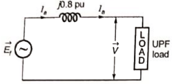 Given,
Xs = 0.8 pu
 Let, Ef ∠ δ be the excitation voltage
Now, power supplied = 1 pu

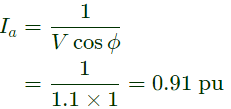 Now,
Now,
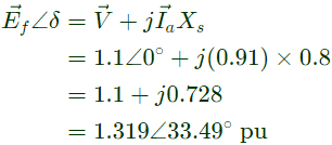
 Hence, the angle of the voltage behind the synchronous reactance = Power angle (δ)
δ = 33.49
Q24: In a synchronous machine, hunting is predominantly damped by (SET-3 (2014))
(a) mechanical losses in the rotor
(b) iron losses in the rotor
(c) copper losses in the stator
(d) copper losses in the rotor
Ans: (d)
Sol: Hunting is a phenomenon occuring in case of synchronous generator and motor where the machine oscillates about the equilibrium point. To reduce this phenomenon, damper bars are used which are embedded in the rotor pole faces of the synchronous machines. Thus, these damper bars causes additional copper loss in the rotor for damping the undesirable phenomenon of hunting.
Q25: A 20-pole alternators is having 180 identical stator slots with 6 conductors in each slot. All the coils of a phase are in series. If the coils are connected to realize single-phase winding, the generated voltage is V1. If the coils are reconnected to realize three phase star connected winding, the generated phase voltage is V2. Assuming full pitch, single-layer winding, the ratio V1/V2 is (SET-2 (2014))
(a) 1/√3
(b) 1/2
(c) √3
(d) 2
Ans: (d)
Q26: A three phase synchronous generator is to be connected to the infinite bus. The lamps are connected as shown in the figure for the synchronization. The phase sequence of bus voltage is R-Y-B and that of incoming generator voltage is R' - Y' - B'.
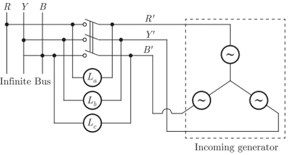 It was found that the lamps are becoming dark in the sequence La−Lb−Lc. It means that the phase sequence of incoming generator is (SET-1 (2014))
(a) opposite to infinite bus and its frequency is more than infinite bus
(b) opposite to infinite bus but its frequency is less than infinite bus
(c) same as infinite bus and its frequency is more than infinite bus
(d) same as infinite bus and its frequency is less than infinite bus
Ans: (a)
Sol: As,
La is connected between R - R’
Lb is connected between Y - Y’
Lc is connected between B - B’
therefore, the given method of synchronization is called "synchronization by dark lmap method".
In this method of synchronization, correct phase sequence of the incoming generator is obtain when all the three lamps become dark together and bright together. Since lamps are becoming dark in the sequence La− Lb− Lc therefore, the phase sequence of incoming generator is opposite to the infinite bus.
Q27: A star connected 400 V, 50 Hz, 4 pole synchronous machine gave the following open circuit and short circuit test results :
Open circuit test : Voc = 400 V (rms, line-to-line) at field current, If = 2.3 A
Short circuit test : Isc= 10 A (rms, phase) at field current, If = 1.5 A
The value of per phase synchronous impedance in Ω at rated voltage is_____. (SET-1 (2014))
(a) 5
(b) 10
(c) 15
(d) 20
Ans: (c)
Sol: Given, for VOC = 400 V(rms)
= 400/√3
= 230.94 (Phase value),
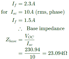 For finding the synchronous impedance at rated voltage, saturation effect of the machine has to be considered (i.e. the adjusted value of Zs)
short circuit ratio,
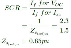 Therefore, actual value of Zs at rated voltage


Q28: The angle δ in the swing equation of a synchronous generator is the (2013)
(a) angle between stator voltage and current
(b) angular displacement of the rotor with respect to the stator
(c) angular displacement of the stator mmf with respect to a synchronously rotating axis
(d) angular displacement of an axis fixed to the rotor with respect to a synchronously rotating axis
Ans: (d)
Q29: The direct axis and quadrature axis reactance's of a salient pole alternator are 1.2 p.u and 1.0 p.u respectively. The armature resistance is negligible. If this alternator is delivering rated kVA at upf and at rated voltage then its power angle is (2011)
(a) 30°
(b) 45°
(c) 60°
(d) 90°
Ans: (b)
Sol: 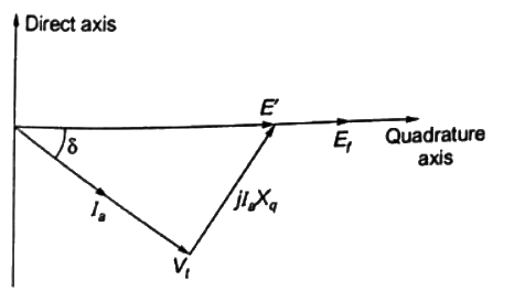 Power angle is the angle between Ef and Vt but as the E′ and Ef are in phase, angle between E′ and Vt = power-angle = δ
Rated power is delivered at upl, so Ia and Vt are in phase
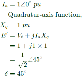
Q30: A three phase, salient pole synchronous motor is connected to an infinite bus. It is operated at no load a normal excitation. The field excitation of the motor is first reduced to zero and then increased in reverse direction gradually. Then the armature current (2011)
(a) Increases continuously
(b) First increases and then decreases steeply
(c) First decreases and then increases steeply
(d) Remains constant
Ans: (b)
Sol: As field current reduces, the flux will start reducing, to keep this flux constant, the armature draws high current from bus.
Ar zero field current the motor acts as synchronous reluctance motor in this case the magnetizing current fully taken from bus. Ie we increase field current in reverse direction to keep flux constant, motor draws more current. During this process the load angle increases at one point the reversed field force dominates reluctance torque and rotor slip one pole pitch anf align to opposite pole. The instant align to opposite pole the flux will be very high, to reduce this flux current drops steeply t synchronous motor value. Here torque is reluctance + synchronous motor torque.
Q31: A field excitation of 20 A in a certain alternator results in an armature current of 400 A in short circuit and a terminal voltage of 2000 V on open circuit. The magnitude of the internal voltage drop within the machine at a load current of 200 A is (2009)
(a) 1V
(b) 10V
(c) 100V
(d) 1000V
Ans: (d)
Sol: If Ra is neglected,
 For a given field current under short-circuit condition,
 But,
But, 
(open circuit voltage i.e. Ia = 0 with the same field current).
Then with the linearity assumption
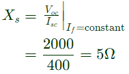 Internal voltage drop
IaXs = 200 × 5 = 1000V
Q32: A synchronous motor is connected to an infinite bus at 1.0 pu voltage and draws 0.6 pu current at unity power factor. Its synchronous reactance is 1.0 pu resistance is negligible.
Keeping the excitation voltage same, the load on the motor is increased such that the motor current increases by 20%. The operating power factor will become (2008)
(a) 0.995 lagging
(b) 0.995 leading
(c) 0.791 lagging
(d) 0.848 leading
Ans: (a)
Sol: Let power factor = cos∅ lagging


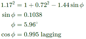
Q33: A synchronous motor is connected to an infinite bus at 1.0 pu voltage and draws 0.6 pu current at unity power factor. Its synchronous reactance is 1.0 pu resistance is negligible.
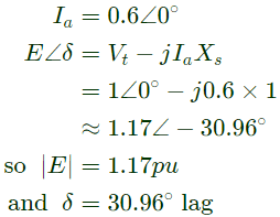
The excitation voltage (E) and load angle (δ) will respectively be (2008)
(a) 0.8 pu and 36.86° lag
(b) 0.8 pu and 36.86° lead
(c) 1.17 pu and 30.96° lead
(d) 1.17 pu and 30.96° lag
Ans: (d)
Sol: 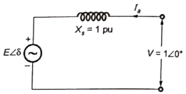 Motor draws 0.6 pu current at upf
Q34: Distributed winding and short chording employed in AC machines will result in (2008)
(a) increase in emf and reduction in harmonics
(b) reduction in emf and increase in harmonics
(c) increase in both emf and harmonics
(d) reduction in both emf and harmonics
Ans: (d)
Sol: Distribution factor in distributed winding 
kd is always less than 1, so emf reduces.
If, mnγ/2 is chosen in such a way that sin(mnγ/2) = 0, nth harmonic gets eliminated.
Similarly,
pitch factor = kp (nth harmonic) = cos (nα/2)
kp is always less than 1, so emf reduces.
If nα/2 is chosen in such a way that cos (nα/2) = 0, nth harmonic gets eliminated.
Q35: A 100 kVA, 415 V(line), star-connected synchronous machine generates rated open circuit voltage of 415 V at a field current of 15 A. The short circuit armature current at a field current of 10 A is equal to the rated armature current. The per unit saturated synchronous reactance is (2007)
(a) 1.731
(b) 1.5
(c) 0.666
(d) 0.577
Ans: (c)
Sol: 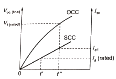 Rated open circuit voltage is obatined at of′′ = 15A
Rated armature current= 
Short-circuit characteristics is linear.
Short-circuit armature current at field current 15A
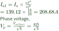 Saturated synchronous reactance
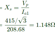
 Per unit saturated synchronous reactance
Q36: A three-phase synchronous motor connected to ac mains is running at full load and unity power factor. If its shaft load is reduced by half, with field current held constant, its new power factor will be (2007 )
(a) unity
(b) leading
(c) lagging
(d) dependent on machine parameters
Ans: (b)
Sol: 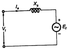 Neglecting armature resistance Ra

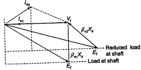 It can be seen from the phasor diagram that, when load is reduced at shaft keeping field current constant the new power factor becomes leading.
Q37: A 4 pole, 50 Hz, synchronous generator has 48 slots in which a double layer winding is housed. Each coil has 10 turns and is short pitched by an angle to 36° electrical. The fundamental flux per pole is 0.025 Wb.
The fifth harmonic component of phase emf(in volts), for a three phase star connection is (2006)
(a) 0
(b) 269
(c) 281
(d) 808
Ans: (a)
Sol: Pitch factor due to 5th harmonic component,
 [as pitch factor is zero, induced emf due to 5th harmonic component is zero]
Q38: A 4 pole, 50 Hz, synchronous generator has 48 slots in which a double layer winding is housed. Each coil has 10 turns and is short pitched by an angle to 36° electrical. The fundamental flux per pole is 0.025 Wb.
The line-to-line induced emf(in volts), for a three phase connection is approximately (2006)
(a) 1143
(b) 1332
(c) 1617
(d) 1791
Ans: (c)
Q39: A 4 pole, 50 Hz, synchronous generator has 48 slots in which a double layer winding is housed. Each coil has 10 turns and is short pitched by an angle to 36° electrical. The fundamental flux per pole is 0.025 Wb.
The line-to-line induced emf(in volts), for a three phase star connection is approximately (2006)
(a) 808
(b) 888
(c) 1400
(d) 1538
Ans: (c)
Sol: In double layer winding
No. of coil = No. of slots = 48
Each coil has 10 turns
Total no. of turns = 48×10 = 480
Tph = No. of turns/phase
= 480/3 = 160
Slots/pole/phase = m = 48/(4x3) = 4
γ = slot angle
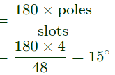 Distribution factor,
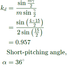 For the nth harmonic, pitch factor,
 pitch factor due to fundamental component
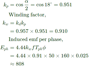 ⇒
⇒
Q40: A 3-phase, 400 V, 5 kW, star connected synchronous motor having an internal reactance of 10 Ω is operating at 50% load, unity p.f. Now, the excitation is increased by 1%. What will be the new load in percent, if the power factor is to be kept same? Neglect all losses and consider linear magnetic circuit. (2006)
(a) 67.90%
(b) 56.90%
(c) 51%
(d) 50%
Ans: (a)
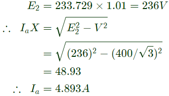
Sol: 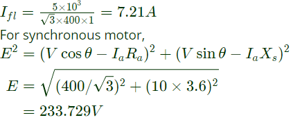 If there is 1% increase in E2, then E2 becomes,

 Given,
 Let, Ef ∠ δ be the excitation voltage
 Now,
Now,
 Hence, the angle of the voltage behind the synchronous reactance = Power angle (δ)
 It was found that the lamps are becoming dark in the sequence La−Lb−Lc. It means that the phase sequence of incoming generator is (SET-1 (2014))
 For finding the synchronous impedance at rated voltage, saturation effect of the machine has to be considered (i.e. the adjusted value of Zs)
 Therefore, actual value of Zs at rated voltage

 Power angle is the angle between Ef and Vt but as the E′ and Ef are in phase, angle between E′ and Vt = power-angle = δ
 For a given field current under short-circuit condition,
 But,
But, 
 Internal voltage drop


 Motor draws 0.6 pu current at upf

 Rated open circuit voltage is obatined at of′′ = 15A
 Saturated synchronous reactance
 Per unit saturated synchronous reactance
 Neglecting armature resistance Ra
 It can be seen from the phasor diagram that, when load is reduced at shaft keeping field current constant the new power factor becomes leading.
 [as pitch factor is zero, induced emf due to 5th harmonic component is zero]
 Distribution factor,
 For the nth harmonic, pitch factor,
  pitch factor due to fundamental component
 ⇒
⇒
 If there is 1% increase in E2, then E2 becomes,


