Resistance & Resistivity | Physics for Grade 12 PDF Download

Resistance
- Resistance is defined as the opposition to current
- For a given potential difference: The higher the resistance the lower the current
- Wires are often made from copper because copper has a low electrical resistance
- Materials with low resistance are known as good conductors
- The resistance R of a conductor is defined as the ratio of the potential difference V across to the current I in it
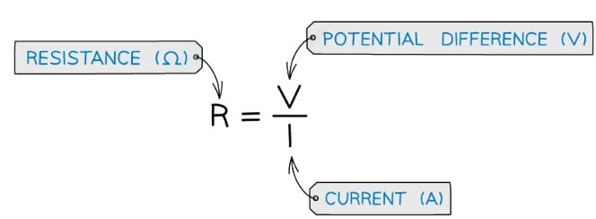
- Resistance is measured in Ohms (Ω)
- Ω is the Greek capital letter 'Omega'
- An Ohm is defined as one volt per ampere (1 V A-1)
- The resistance controls the size of the current in a circuit
- A higher resistance means a smaller current
- A lower resistance means a larger current
- All electrical components, including wires, have some value of resistance
Example: Calculate the potential difference through a resistor of resistance 10 Ω if there is a current of 0.3 A through it.
Step 1: List the known quantities
- Resistance, R = 10 Ω
- Current, I = 0.3 A
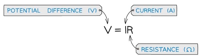
Step 2: Write the resistance equation
Step 3: Rearrange for V
V = IR
Step 4: Substitute in the values
V = 0.3 × 10 = 3 V

Ohm's Law & I-V Characteristics
- Ohm’s law states:
- For a conductor at a constant temperature, the current through it is proportional to the potential difference across it
- Constant temperature implies constant resistance
- Ohm's law is represented in the equation below:
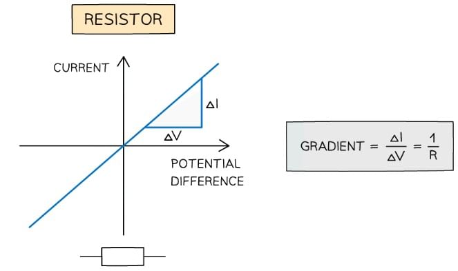
- Measuring the variation of current with potential difference through a fixed resistor will produce a straight line graph, such as the one below
 Circuit for plotting graphs of current against voltage
- Since the gradient is constant, the resistance R of the resistor can be calculated by using 1 ÷ gradient of the graph
- An electrical component obeys Ohm’s law if its graph of current against potential difference is a straight line through the origin
- A resistor does obey Ohm’s law
- A filament lamp does not obey Ohm’s law
- This applies to any metal wires, provided that the current isn’t large enough to increase their temperature
I–V Characteristics
- As the potential difference (voltage) across a component is increased, the current also increases (by Ohm’s law)
- The precise relationship between voltage and current is different for different components and can be shown on an I–V graph
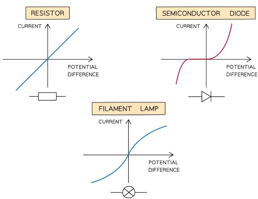
- For an ohmic conductor eg. a fixed resistor:
- The I–V graph is a straight line through the origin
- For a non-ohmic conductor, such as
- A semiconductor diode, the I–V graph is a horizontal line that goes sharply upwards
- An LED (light-emitting diode), the I–V graph is similar to the semiconductor diode, since it is a specific diode that emits visible light
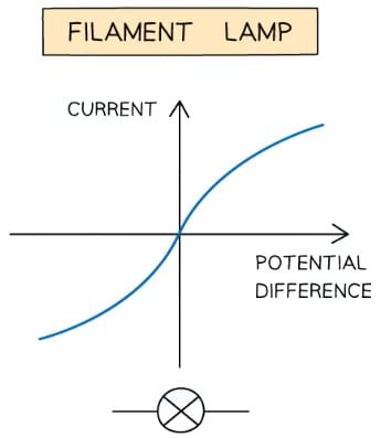
- A filament lamp, the I–V graph has an 'S' shaped curve
- A thermistor, the I–V graph is a curved line with increasing gradient through the origin
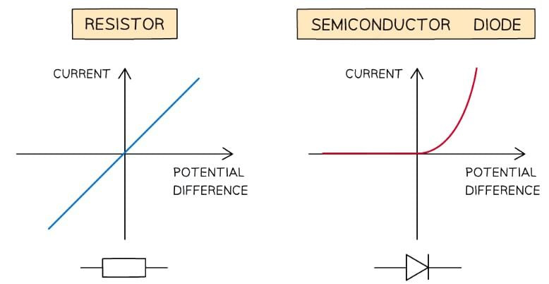
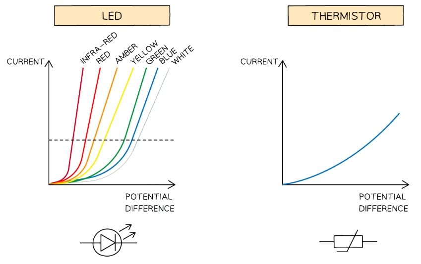 I–V characteristics for an ohmic conductor (e.g. resistor), semiconductor diode, filament lamp, LED and thermistor
Ohmic Conductor
- The I–V graph for an ohmic conductor at constant temperature e.g. a resistor is very simple:
- The current is directly proportional to the potential difference
- This is demonstrated by the straight-line graph through the origin
Semiconductor Diode
- The I–V graph for a semiconductor diode is slightly different. A diode is used in a circuit to allow current to flow only in a specific direction
- When the current is in the direction of the arrowhead symbol, this is forward bias
- This is shown by the sharp increase in potential difference and current on the right side of the graph
- When the diode is switched around, it does not conduct and is called reverse bias
- This is shown by a zero reading of current or potential difference on the left side of the graph which then goes steeply vertically down
- For an LED, the I–V graph is identical, except the sharp increase in p.d is further away from the origin as the frequency of the light increases
Filament Lamp
- The I–V graph for a filament lamp shows the current increasing at a proportionally slower rate than the potential difference
- This is because:
- As the current increases, the temperature of the filament in the lamp increases
- Since the filament is a metal, the higher temperature causes an increase in resistance
- Resistance opposes the current, causing the current to increase at a slower rate
- Where the graph is a straight line, the resistance is constant
- The resistance increases as the graph curves
- The filament lamp obeys Ohm's Law for small voltages
Thermistor
- The I–V graph for a thermistor is a shallow curve upwards
- The increase in the potential difference results in an increase in current which causes the temperature of the thermistor to rise
- As its temperature rises, its resistance decreases
- This means even more current is able to flow through
- Since the current is not directly proportional to the potential difference (the graph is still curved), the thermistor does not obey Ohm's Law
Example: The I–V characteristic of two electrical component X and Y are shown.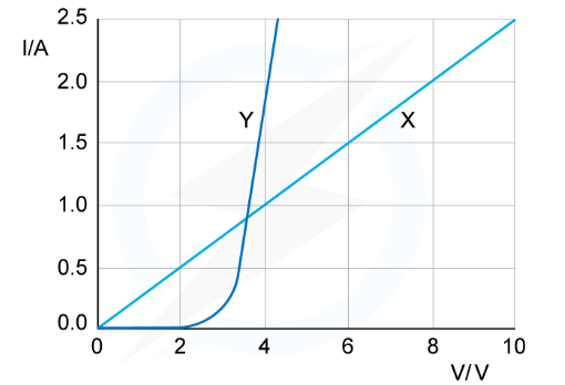 Which statement is correct?
(A) The resistance of X increases as the current increases
(B) At 2 V, the resistance of X is half the resistance of Y
(C) Y is a semiconductor diode and X is a resistor
(D) X is a resistor and Y is a filament lamp
- The I–V graph X is linear
- This means the graph has a constant gradient. I/V and the resistance is therefore also constant (since gradient = 1/R)
- This is the I–V graph for a conductor at constant temperature e.g. a resistor
- The I–V graph Y starts with zero gradient and then the gradient increases rapidly
- This means it has infinite resistance at the start which then decreases rapidly
- This is characteristic of a device that only has current in one direction e.g a semiconductor diode
- Therefore, the answer is C
Investigating Electrical Characteristics of Components
Aim of the Experiment
- The aim of the experiment is to investigate electrical characteristics for a range of ohmic and non-ohmic components
- These include a fixed resistor, lamp and diode
Variables:
- Independent variable = Potential difference, V
- Dependent variable = Current, I
- Control variables:
- E.m.f of the power supply
- Use of the same equipment eg. wires, diodes
Equipment List
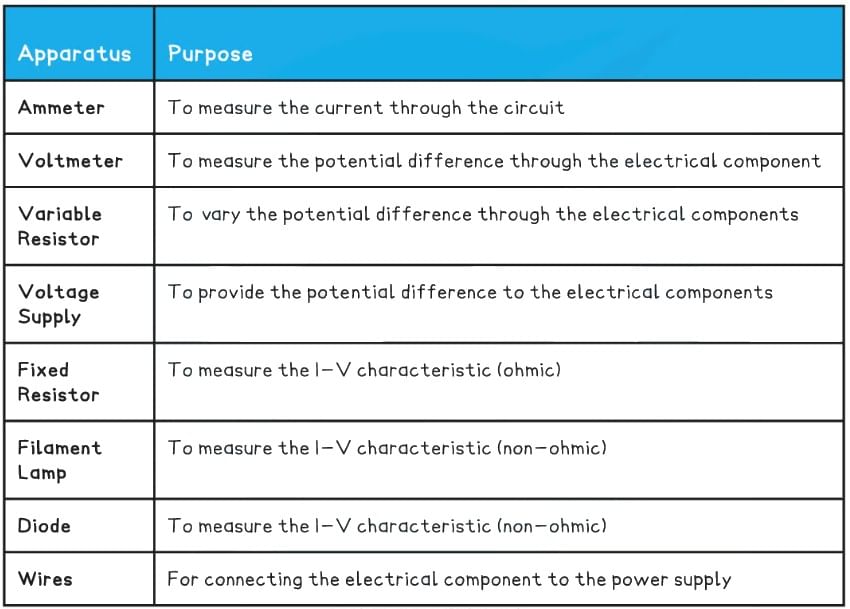
- Resolution of measuring equipment:
- Variable resistor = 0.005 Ω
- Voltmeter = 0.1 V
- Ammeter = 0.01 A
Method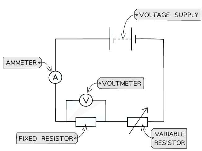 Circuit diagram of the apparatus set up. The fixed resistor will be replaced by a filament lamp and diode
- Set up the circuit as shown with the fixed resistor
- Vary the voltage across the component by changing the resistance of the variable resistor, using a wide range of voltages (between 8-10 readings). Check the appropriate voltage reading on the voltmeter
- For each voltage, record the value of the current from the ammeter 3 times and
- calculate the average current
- Increase the voltage further in steps of 0.5 V and repeat steps 2 and 3
- Make sure to switch off the circuit in between readings to prevent heating of the component and wires
- Reverse the terminals of the power supply and take readings for the negative voltage (and therefore negative current)
- Replace the fixed resistor with the filament lamp, then the diode, repeating the experiment for each
An example of a suitable table might look like this: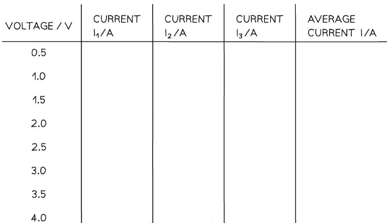
Analysis of Results
- Plot a graph of average current against voltage (an I-V graph) for each component
- If the I-V graph is a straight line, it is an ohmic conductor. This is expected from the fixed resistor
- This means it obeys Ohm's Law: V = IR
- If the I-V graph is a curve, it is a non-ohmic conductor. This is expected from the filament lamp and diode
- Compare the results from the graphs obtained to the known I-V graphs for the resistor, filament lamp and diode. These should look like:
 The expected I-V graphs for the resistor, diode and filament lamp
Evaluating the Experiment
- Systematic Errors: The voltmeter and ammeters should start from zero, to avoid zero error in the readings
- Random Errors: In practice, the voltmeter and ammeter will still have some resistance, therefore the voltages and currents displayed may be slightly inaccurate
- The temperature of the equipment could affect its resistance. This must be controlled carefully
- Taking multiple readings of the current for each component will provide a more accurate result and reduce uncertainties
Safety Considerations
- When there is a high current, and a thin wire, the wire will become very hot. Make sure never to touch the wire directly when the circuit is switched on
- Switch off the power supply right away if burning is smelled
- Make sure there are no liquids close to the equipment, as this could damage the electrical equipment
- The components will get hot especially at higher voltages. Be careful when handling them - especially the filament lamp
- Disconnect the power supply in between readings to avoid the components heating up too much.
The Light-Dependent Resistor (LDR)
- A light-dependent resistor (LDR) is a non-ohmic conductor and sensory resistor
- Its resistance automatically changes depending on the light energy falling onto it (illumination)
- As the light intensity increases, the resistance of an LDR decreases
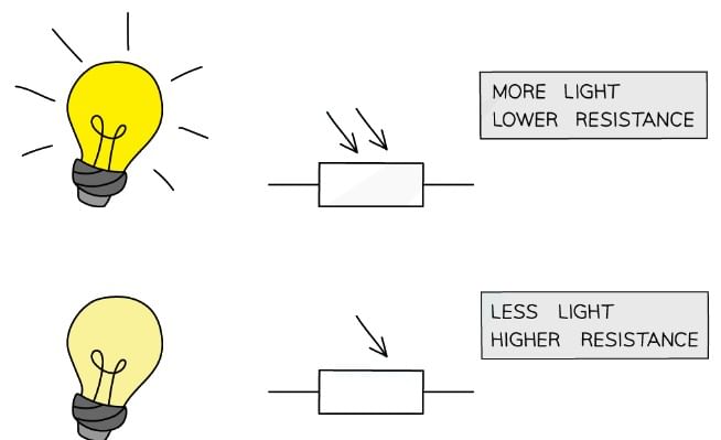 Resistance of an LDR depends on the light intensity falling on it
This is shown by the following graph:
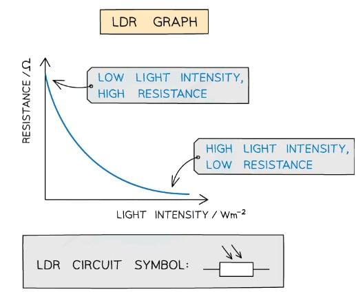 Graph of light intensity and resistance for an LDR
- LDRs can be used as light sensors, so, they are useful in circuits which automatically switch on lights when it gets dark, for example, street lighting and garden lights
- In the dark, its resistance is very large (millions of ohms)
- In bright light, its resistance is small (tens of ohms)
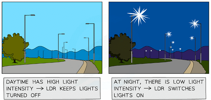 LDRs are used for automatic street lights
Resistivity
- All materials have some resistance to the flow of charge
- As free electrons move through a metal wire, they collide with ions which get in their way
- As a result, they transfer some, or all, of their kinetic energy on collision, which causes electrical heating
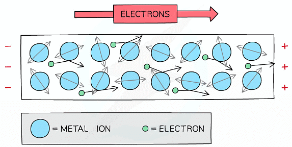 Free electrons collide with ions which resist their flow
- Since current is the flow of charge, the ions resisting their flow causes resistance
- Resistance depends on the length of the wire, the cross-sectional area through which the current is passing and the resistivity of the material
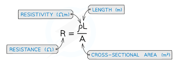
- The resistivity equation shows that:
- The longer the wire, the greater its resistance
- The thicker the wire, the smaller its resistance
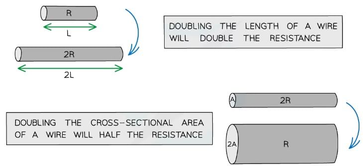 The length and width of the wire affect its resistance
- Resistivity is a property that describes the extent to which a material opposes the flow of electric current through it
- It is a property of the material, and is dependent on temperature
- Resistivity is measured in Ω m
Resistivity of some materials at room temperature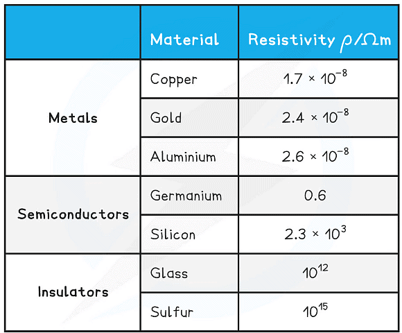
- The higher the resistivity of a material, the higher its resistance
- This is why copper, with its relatively low resistivity at room temperature, is used for electrical wires — current flows through it very easily
- Insulators have such a high resistivity that virtually no current will flow through them
Example: Two electrically-conducting cylinders made from copper and aluminium respectively. Their dimensions are shown below.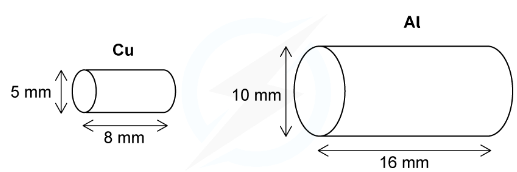
Copper resistivity = 1.7 × 10⁻⁸ Ω m
Aluminium resistivity = 2.6 × 10⁻⁸ Ω m
Which cylinder is the better conductor?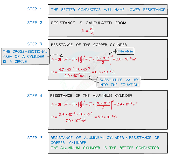
Variation of the Resistivity of Metals and Semiconductors
- The resistivity of a material depends on its temperature
- How it varies depends on whether the material is a metal or a semiconductor
Metals
- All solids are made up of vibrating atoms
- As the temperature rises, the ions vibrate with a greater frequency and amplitude
- Electric current is the flow of free electrons in a material
- The electrons collide with the vibrating atoms which impede their flow, hence the current decreases
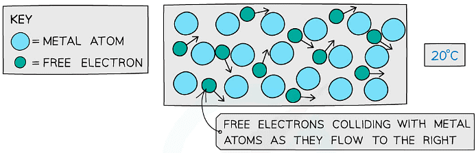
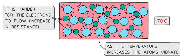 Metal atoms and free electrons at low and high temperatures
- So, if the current decreases, then the resistance will increase (from V = IR)
- Therefore, its resistivity will increase since ρ ∝ R (if the area A and length L is constant)
- For a metallic conductor which obeys Ohm's law:
- An increase in temperature causes an increase in resistance and resistivity
- A decrease in temperature causes a decrease in resistance and resistivity
Semiconductors
- The resistivity of semiconductors behaves in the opposite way to metals
- The number density of charge carriers (such as electrons) increases with increasing temperature
- Therefore, for a semiconductor:
- An increase in temperature causes a decrease in resistance and resistivity
- A decrease in temperature causes an increase in resistance and resistivity
- One example of this is a thermistor
- This is often used in temperature sensing circuits such as thermometers and thermostats
- This is only for semiconductors with a negative temperature coefficient (NTC)
Determining the Resistivity of a Metal
Aims of the Experiment
- The aim of the experiment is to determine the resistivity of a 2 metre constantan wire
Variables:
- Independent variable = Length, L, of the wire (m)
- Dependent variable = The current, I, through the wire (A)
- Control variables:
- Voltage through the wire
- The material the wire is made from
Equipment List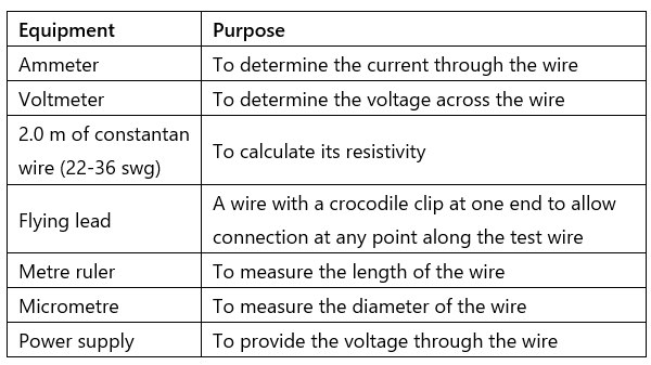
Resolution of measuring equipment:
- Metre ruler = 1 mm
- Micrometer screw gauge = 0.01 mm
- Voltmeter = 0.1 V
- Ammeter = 0.01 A
Method
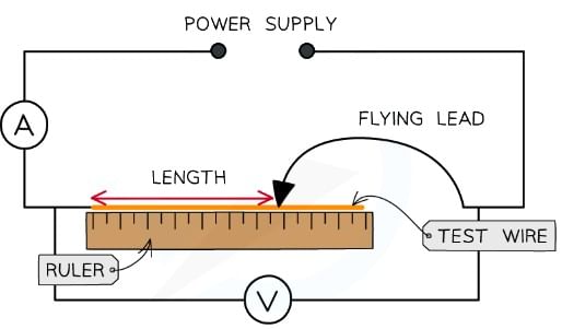
- Measure the diameter of the constantan wire using a micrometer. The measurement should be taken between 5-10 times randomly along the wire. Calculate the mean diameter from these values
- Set up the equipment so the wire is taped or clamped to the ruler with one end of the circuit attached to the wire where the ruler reads 0. The ammeter is connected in series and the voltmeter in parallel to the wire
- Attach the flying lead to the test wire at 0.25 m and set the power supply at a voltage of 6.0 V. Check that this is the voltage through the wire on the voltmeter
- Read and record the current from the ammeter, then switch off the current immediately after the reading (the short wire will get very hot)
- Vary the distance between the fixed end of the wire and the flying lead in 0.25 m intervals (0.25 m, 0.50 m, 0.75 etc.) until the full length of the 2.0 m wire. The original length and the intervals can be changed (e.g. start at 0.1 m and increase in 0.1 m intervals), as long as there are 8-10 readings
- Record the current for each length at least 3 times and calculate an average current, I
- For each length, calculate the average resistance of the length of the wire using the equation

- Where V is the voltage and I is the average current through the wire for that length
- An example of a table of results might look like this:
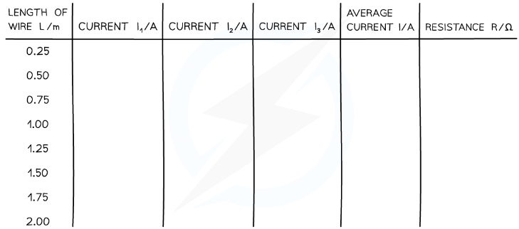
Analysis of Results
- The resistivity, ρ, of the wire is equal to

- Where:
- ρ = resistivity (Ω m)
- R = resistance (Ω)
- A = cross-sectional area of the wire (m2)
- L = length of wire (m)
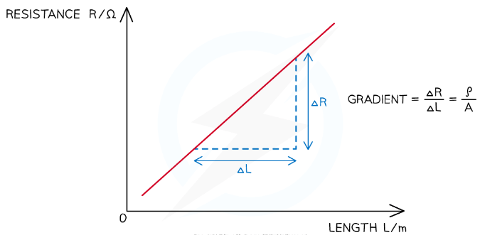
- Rearranging for the resistance, R:

- Comparing this to the equation of a straight line: y = mx
- y = R
- x = L
- Gradient = ρ / A
- The resistivity can therefore be calculated from the gradient of the resistance against length graph, multiplied by the cross-sectional area of the wire
1. Calculate the cross-sectional area, A, of the wire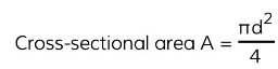
2. Plot a graph of the length of the wire, L, against the average resistance of the wire, R3. Draw a line of best fit and calculate the gradient of this graph4. Calculate the resistivity ρ by multiplying the gradient by the cross-sectional area A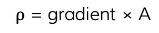
Evaluating the Experiment
Systematic Errors:
- The end of the wire that is attached to the circuit (not the flying lead) must start at 0 on the ruler
- Otherwise, this could cause a zero error in your measurements of the length
Random Errors:
- Only allow small currents to flow through the wire
- The resistivity of a material depends on its temperature. The current flowing through the wire will cause its temperature to increase and affect its resistance and resistivity. Therefore the temperature is kept constant and low by small currents
- The current should be switched off between readings so its temperature doesn't change its resistance
- Make at least 5-10 measurements of the diameter of the wire with the micrometer screw gauge and calculate an average diameter to reduce random errors in the reading
Safety Considerations
- When there is a high current, and a thin wire, the wire will become very hot
- Make sure never to touch the wire directly when the circuit is switched on
- Switch off the power supply right away if burning is smelled
- Make sure there are no liquids close to the equipment, as this could damage the electrical equipment
Thermistors
- A thermistor is a non-ohmic conductor and sensory resistor whose resistance varies with temperature
- Most thermistors are negative temperature coefficient (ntc) components
- This means that if the temperature increases, the resistance of the thermistor decreases (and vice versa)
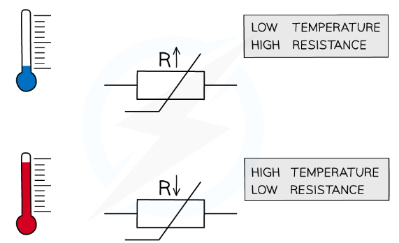 The resistance through a thermistor is dependent on the temperature of it
- The temperature-resistance graph for a thermistor is shown below
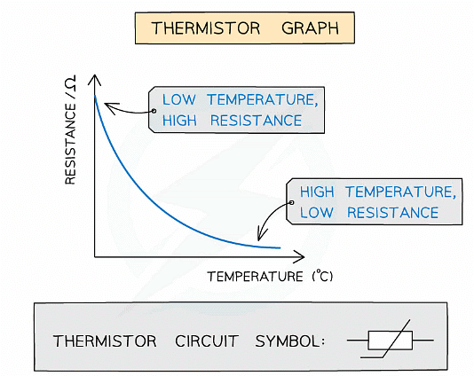 Graph of temperature against resistance for a thermistor
- Thermistors are temperature sensors and are used in circuits in ovens, fire alarms and digital thermometers
- As the thermistor gets hotter, its resistance decreases
- As the thermistor gets cooler, its resistance increases
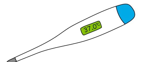 A digital thermometer uses a thermistor
Example: A thermistor is connected in series with a resistor R and a battery.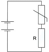
The resistance of the thermistor is equal to the resistance of R at room temperature.When the temperature of the thermistor decreases, which statement is correct?
(A) The p.d across the thermistor increases
(B) The current in R increases
(C) The current through the thermistor decreases
(D) The p.d across R increases
- The resistance of the thermistor increases as the temperature decreases
- Since the thermistor and resistor R are connected in series, the current I in both of them is the same
- Ohm’s law states that V = IR
- Since the resistance of the thermistor increases, and I is the same, the potential difference V across it increases
- Therefore, statement A is correct
|
142 videos|312 docs|132 tests
|


Viva Questions
,Objective type Questions
,MCQs
,Important questions
,past year papers
,Resistance & Resistivity | Physics for Grade 12
,Resistance & Resistivity | Physics for Grade 12
,Resistance & Resistivity | Physics for Grade 12
,ppt
,Summary
,Sample Paper
,shortcuts and tricks
,Semester Notes
,video lectures
,Extra Questions
,study material
,Exam
,Previous Year Questions with Solutions
,practice quizzes
,mock tests for examination
,Free
;


Resistance & Resistivity Free PDF Download
Importance of Resistance & Resistivity
Resistance & Resistivity Notes
Resistance & Resistivity Grade 12 Questions
Study Resistance & Resistivity on the App
|
© EduRev
|
Education Revolution
|


|


within 7 days!