Resistive Transducers | Sensor & Industrial Instrumentation - Electronics and Communication Engineering (ECE) PDF Download
Resistive Transducers
In genera], the resistance of a metal conductor is given by,
R = ρL / A
where ρ = Resistivity of conductor (Ω m)
L = Length of conductor (m)
A = Area of cross-section of conductor (m2)
The electrical resistive transducers are designed on the basis of the methods of variation of any one of the quantities in above equation; such as change in length, change in area of cross-section and change in resistivity. The resistive transducers can be used either as primary transducers or secondary transducers. The methods based on measurement of the resistance change are most widely used in various industrial applications as,(i) Both a.c. and d.c. voltages and currents are suitable for the measurement of resistance change.
(ii) The speed of response of the resistive transducers is high.
(iii) They are available in various sizes with wide range of resistance value.
(iv) High resolution in measurements can be achieved as large variety of electrical circuits are available.
The resistance change due to the change in the length of the conductor is used in translational or rotational potentiometers to measure linear or rotational displacement. The change in resistance of conductor or semiconductor due to the strain applied is the working principle of the strain gauge which is used to measure various physical quantities such as pressure, displacement and force. The change in resistivity of conductor due to the temperature variations causes change in resistance. This principle is used to measure temperature.
The range of electrical quantities that can be measured using the resistive transducers either as primary transducer or secondary transducer.
Table 8.1 Resistance transducers and measurands
Potentiometric Resistance Transducer
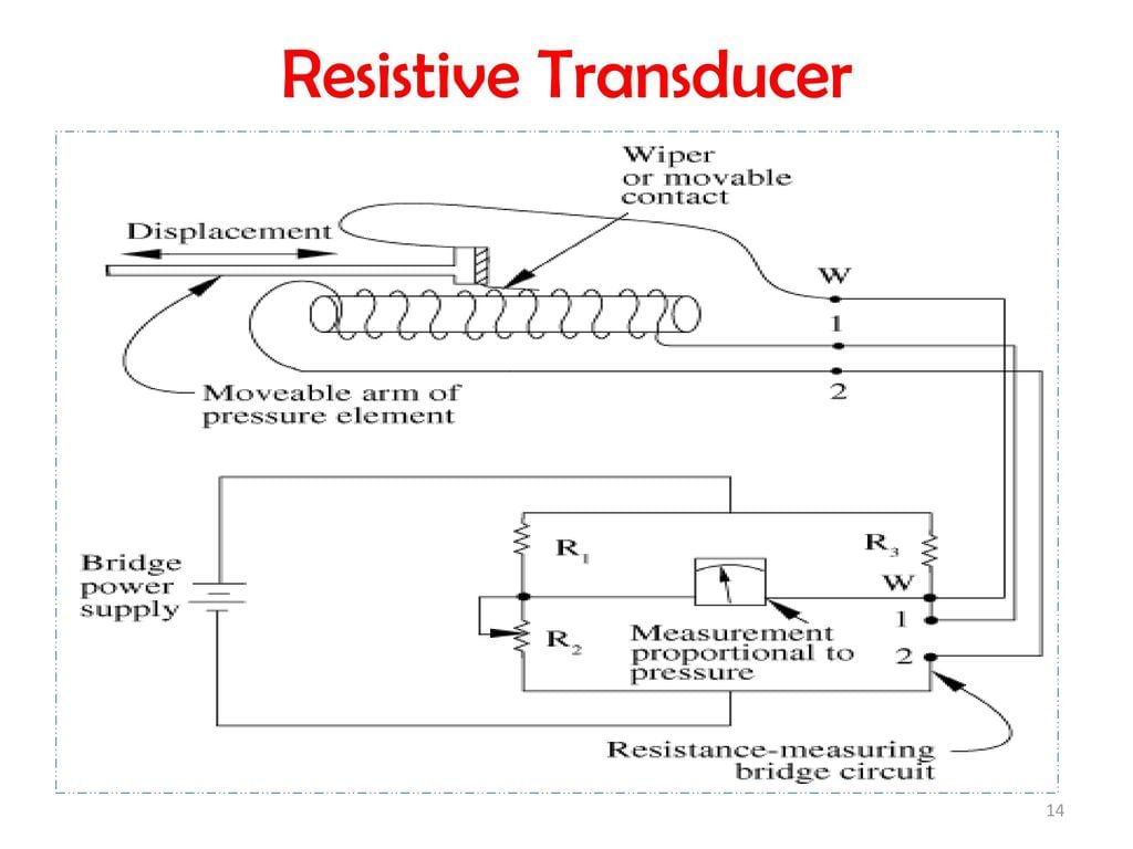
A potentiometric resistance transducer (or simply potentiometer) is generally used to measure linear or angular displacement. A resistance potentiometer consists a wire wound resistive element along with a sliding contact which is called as wiper. A wire is made up of platinum or nickel alloy with diameter as small as 0.01 mm. The resistive element is made up of cement hot moulded carbon or carbon film. The wire is wound on an insulating former. The linear and rotary potentiometers are as shown in the Fig. 8.12. Fig. 8.12 Resistance potentiometers
Using resistance potentiometers mechanical displacement is converted into an electrical output. Linear or angular displacement is applied to the sliding contact and then the corresponding change in resistance is converted into voltage or current. Note that the resistance potentiometers shown in the Fig. 8.12 may be excited by either a.c. voltage or d.c. voltage. To measure combination of linear (translational) and angular (rotational) motion, the helipots are used. As the resistive element in such potentiometer is in the form of helix, it is called helipot.
Advantages and Disadvantages of Resistance Potentiometers
The advantages of resistance potentiometers are as follows:
- Simple in construction and operation.
- Best suitable for measurements in the systems with least requirements.
- High electrical efficiency and provides sufficient output for further control operations.
- Useful for displacement measurements of large amplitudes.
- Inexpensive.
The disadvantages of resistance potentiometers are as follows:
- In linear potentiometers, large force is required to move wiper.
- Suffer from mechanical wear and misallignment of wiper.
- Limited resolution and high electronic noise in output.
|
23 videos|24 docs|29 tests
|

|
Explore Courses for Electronics and Communication Engineering (ECE) exam
|

|


