Schmitt Trigger | Digital Electronics - Electrical Engineering (EE) PDF Download

What is Schmitt Trigger?
The Schmitt Trigger was designed by American researcher Otto H Schmitt in 1934. A Schmitt trigger is a type of comparator with hysteresis. It takes an analog signal as an input and converts it into a perfect and stable output signal. It does this by applying positive feedback to the non-inverting input of a comparator. The main purpose of the Schmitt trigger is to eliminate noise or jitter in the input signal and produce a stable output. This is especially true when dealing with signals that switch between two voltage levels.
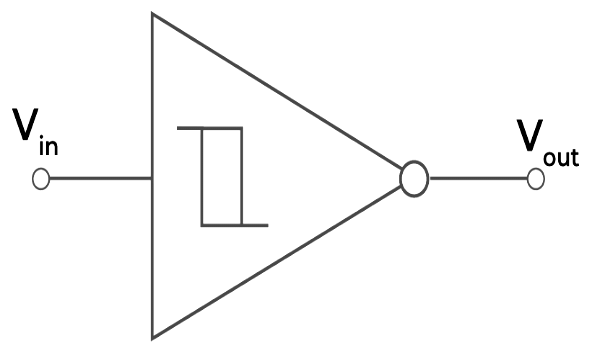 Symbol of Schmitt Trigger
Characteristics of the Schmitt Trigger
- Hysteresis: It is the defining feature of the Schmitt Trigger. It means that the output voltage depends on the previous values of input signals. This hysteresis helps in creating two different voltage thresholds. The first threshold value is for the rising input and the other is for the falling input signal.
- Noise Rejection: The hysteresis helps in noise rejection. When there are small fluctuations in the input signal, the output signal does not change or does not show false values. It helps in preventing the noise coming from the noisy environment.
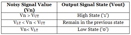
- Bistable Operation: Bistable operation means that it has two possible stable states i.e., ‘high state’ and ‘low state’. When the upper threshold value is crossed by the input signal, the output signal changes its state to ‘high’. The output signal remains in this state until the input signal value falls below the threshold value. When the value falls below the threshold value, the state changes to ‘low’.
Working of Schmitt Trigger
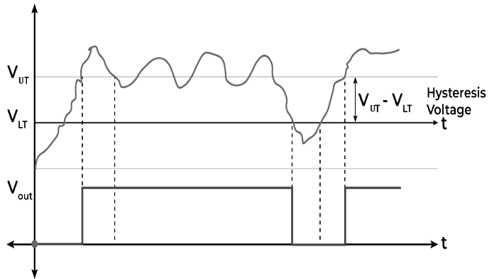
The comparator works properly when the input signal does not contain any noise. If the noise is present than comparator does not work properly. When the noisy signal is present, the Schmitt trigger gives proper results. It uses two threshold voltages i.e., upper threshold voltage (VUT) and lower threshold voltage (VLT). Let us understand the working of Schmitt Trigger with the help of given graph.
 Working
From the above diagram, the signal which is red in color is the noisy signal. When the signal value is lower than upper threshold voltage, the output voltage remains in low state (‘0’ state). When the upper threshold value is crossed by the noise signal, the output voltage moves to high state (‘1’ state). The output signal will change its state to low when the noisy signal crosses the lower threshold value.
In this way the Schmitt Trigger works and helps in preventing continuous switching in the device due to noisy signal.
Transfer Characteristic of Schmitt Trigger
There are two types of Schmitt Trigger:
- Non-Inverting Schmitt Trigger
- Inverting Schmitt Trigger
Non-Inverting Schmitt Trigger
When the input signal is applied at the non-inverting (+ve terminal) terminal and ground is connected to the inverting (-ve terminal) terminal of of Op-Amp, it is called Non-Inverting Schmitt Trigger.
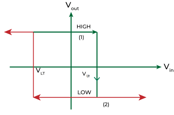
The figure given below shows the transfer characteristics of Non-Inverting Schmitt Trigger. The curve shown is called the hysteresis curve. Let’s study the graph in detail.
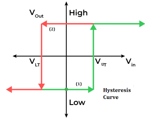 Hysteresis Curve (Non-inverting)
The number ‘1’ marked on the above graph shows that the output voltage will remain low until Vin crosses the VUT. When the input signal crosses the upper threshold voltage, the output voltage becomes HIGH.
The number ‘2’ marked on the above graph shows that if the input signal starts decreasing, Vout will remain high until Vin crosses the lower threshold voltage. When the input signal crosses the VLT, the output voltage becomes LOW.
Hence, it will form a hysteresis curve that keeps on working continuously.
Inverting Schmitt Trigger
When the input signal is applied at the inverting terminal (-ve terminal) and ground is connected to the non-inverting (+ve terminal) terminal of of Op-Amp, it is called Inverting Schmitt Trigger.
The figure given below shows the transfer characteristics of Inverting Schmitt Trigger. The curve shown is called the hysteresis curve. Let’s study the graph in detail.
 Hysteresis Curve (Inverting)
The number ‘1’ marked on the above graph shows that when Vin < VUT, the output signal remains HIGH.
The number ‘2’ marked on the above graph shows that when Vin> VUT, the output voltage will become LOW.
NOTE: The working of Inverting Schmitt Trigger is opposite of Non-Inverting Schmitt Trigger.
Hence, it will form a hysteresis curve that keeps on working continuously.
Schmitt Trigger Circuit and its Types
A Schmitt Trigger circuit is an electronic circuit that uses positive feedback to make hysteresis and give two unique edge voltage levels i.e. ‘Upper Threshold Voltage (VUT)’ and ‘Lower Threshold Voltage (VLT)’ for an information signal. It is divided into two parts:
- Op-amp based Schmitt Trigger
- Transistor based Schmitt Trigger
Op-amp based Schmitt Trigger
It is further classified into two types based on the input signal applied on the inverting or non-inverting terminal of Op-amp:
- Inverting Schmitt Trigger.
- Non-inverting Schmitt Trigger
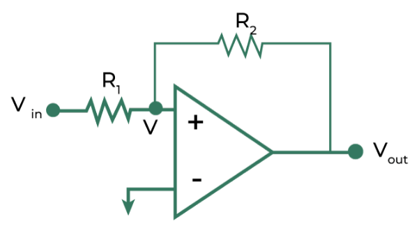
Inverting Schmitt Trigger
When the input is given at the inverting terminal of op-amp and the positive feedback is applied from output to input, it is known as inverting Schmitt Trigger.
 Inverting Schmitt Trigger
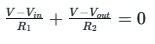
To determine the equation for Inverting Schmitt Trigger circuit, we use the Kirchhoff Law: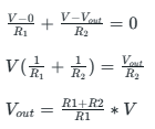
V= Vin (according to virtual ground property of op-amp)
Let’s say that Vout is HIGH at Vin = V1. If Vin is more than V1, then Vout has to become low. Hence, V1 is known as Upper Threshold Voltage and similarly for the Lower Threshold Voltage.
Non-Inverting Schmitt Trigger
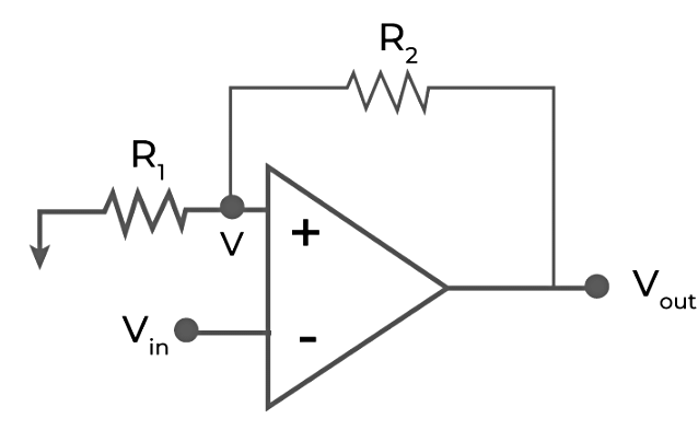
When the input is given at the non-inverting terminal of op-amp and the positive feedback is applied from output to input, it is known as non-inverting Schmitt Trigger.
 Non-Inverting Schmitt Trigger
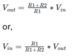
To determine the equation for Non-Inverting Schmitt Trigger circuit, we use the Kirchhoff Law:
V=0 (due to virtual ground property)
Let’s say that Vout is HIGH at Vin = V1. If Vin is less than V1, then Vout has to become low. Hence, V1 is known as Lower Threshold Voltage and similarly for the Upper Threshold Voltage.
Some More Types of Schmitt Trigger
There are following types of Schmitt Trigger based on their working:
- Transistor based Schmitt Trigger
- Schmitt Trigger Oscillator
- CMOS Schmitt Trigger
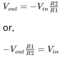
Transistor based Schmitt Trigger
A transistor based Schmitt Trigger uses semiconductors and resistors to make hysteresis for noise-immune signal switching. It is designed using two transistors. It is generally utilized in applications requiring computerized signal dependability and noise rejection.
 Transistor Based Schmitt Trigger
Working
Let’s say Vin = 0V. This means that transistor T1 is in the cutoff. The transistor T2 is conduction because voltage at point B is 1.98V (calculated using voltage divider at point B). As transistor T2 is conduction, the output voltage (Vout) will be low.
When Vin>1.98V, then transistor T1 will start conducting and this will drop the voltage at the base of the transistor T2. This results in making the transistor T2 off and the output voltage will become high.
If Vin falls below 1.98V, the output will become low. In this way the cycle repeats over and over again.
Schmitt Trigger Oscillator
A Schmitt Trigger oscillator is a circuit that utilizes a Schmitt Trigger with positive feedback to produce a square wave yield. It act as a oscillator when RC integrated circuit is connected.
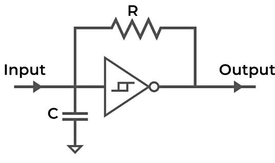 Schmitt Trigger Oscillator
It produces the continuous square wave and the waveform frequency depends on the value of R, C and Vth (threshold point of Schmitt trigger).
Mathematically, frequency is represented as:
f = k/RC
where, k is a constant and it ranges between 0.2 and 1.
CMOS Schmitt Trigger
A CMOS (Corresponding Metal-Oxide-Semiconductor) Schmitt Trigger is an electronic circuit that uses CMOS to make a Schmitt Trigger with exceptionally low power utilization. It utilizes correlative sets of MOSFET semiconductors transistors to accomplish high noise immunity, making it reasonable for battery-worked gadgets and advanced signal handling applications. CMOS Schmitt Triggers have two threshold levels, guaranteeing perfect and stable advanced signal changes while limiting power utilization.
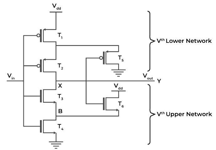 CMOS Schmitt Trigger
Why we use Schmitt Trigger?
A Schmitt Trigger resembles a modern switch for electrical signals. Let’s discuss one condition, i.e., imagine that you have a light that you want to turn on when it’s dark and turn off when it’s bright in a room. A modern switch could turn on and off rapidly when the room light is at the limit of dimness or brightness. This would lead to the flickering of the light.
Presently, you can change that normal switch with a Schmitt Trigger. Thus, it won’t flicker the light anywhere when the lightning is close to the threshold. This process holds until the room is recognizably dull before turning on the light and holds on until it’s lightening in the room before switching it off.
Hence we use Schmitt Trigger to prevent the switch from debouncing, providing noise immune output by using hysteresis. It helps in removing noise from the signal. Due to these advantages, we use Schmitt Trigger as a modern switch.
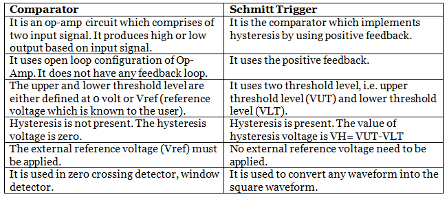
Difference between Schmitt Trigger and Comparator
Advantages and Disadvantages of Schmitt Trigger
Some of the Advantages and Disadvantages of Schmitt Trigger are as follows :
Advantages
- It is cost-effective device as it uses less number of components. It is simple to implement in any electrical circuit.
- It helps in removing the noise from the signal and enhancement of the output.
- It prevents the switch debouncing which helps in reducing the multiple transition of the switch.
- It uses hysteresis which provide two threshold voltage. It helps in providing the noise immune output.
Disadvantages
- It is not suitable in the applications which require high precision like analog-to-digital convertor.
- The working of Schmitt Trigger is dependent on the input voltage level and threshold voltages. If there is a significant change in the input voltage, the output may vary significantly.
- It also exhibits non-linear response. It means small change in the input will lead to the large change in the output.
Applications of Schmitt Trigger
- Oscillators: It is utilized in square wave and unwinding oscillators for creating clock and timing signals.
- Waveform Forming: It is used to shape square waveforms and eliminate noise from signals.
- Debouncing: It is utilized in circuits for switch debouncing to provide stable signal transitions upon switch pressing or releasing.
- Noise immunity: It increases the noise immunity in the circuit with the single input threshold.
Conclusion
In this article, we have studied that a Schmitt Trigger resembles a modern switch for electrical signals. It eliminates the noise and produces a stable signal. It is used in various applications like switch debouncing, oscillators, and many more. We have also studied the working, types of Schmitt Trigger for a better understanding of the topic. It is also used in the signal conditioning applications in order to remove the noise from the signals , used in generators, switching power supplies. So they are used when noisy signals are involved and prevent unwanted oscillations.
|
125 videos|83 docs|58 tests
|
FAQs on Schmitt Trigger - Digital Electronics - Electrical Engineering (EE)
| 1. What is a Schmitt Trigger? |  |
| 2. How does a Schmitt Trigger work? | |
| 3. What is the purpose of hysteresis in a Schmitt Trigger? | |
| 4. What are the typical applications of a Schmitt Trigger? | |
| 5. How can I calculate the threshold voltages for a Schmitt Trigger circuit? | |


mock tests for examination
,Schmitt Trigger | Digital Electronics - Electrical Engineering (EE)
,video lectures
,Extra Questions
,Previous Year Questions with Solutions
,Schmitt Trigger | Digital Electronics - Electrical Engineering (EE)
,Summary
,Objective type Questions
,study material
,Sample Paper
,Semester Notes
,past year papers
,Important questions
,ppt
,Exam
,Free
,practice quizzes
,Schmitt Trigger | Digital Electronics - Electrical Engineering (EE)
,Viva Questions
,MCQs
,shortcuts and tricks
;


Schmitt Trigger Free PDF Download
Importance of Schmitt Trigger
Schmitt Trigger Notes
Schmitt Trigger Electrical Engineering (EE) Questions
Study Schmitt Trigger on the App
|
© EduRev
|
Education Revolution
|


|


within 7 days!