Simple DC circuits with R, L & C components | Electricity & Magnetism - Physics PDF Download
Circuit Analysis by Classical Method
Whenever a circuit is switched from one condition to another, either by a change in the applied source or a change in the circuit elements, there is a transition period during which the branch currents and element voltages change from their former values to new ones. This period is called the transient. After the transient is passed, the circuit is said to be in the steady state. Now, the linear differential equation that describes the circuit will have two parts to its solution. The complementary function corresponds to the transient state and the particular solution corresponds to the steady state. The v-i relation for an inductor or capacitor is a differential equation. A Circuit containing an inductor L or a capacitor C and resistor R will have current and voltage variables given by differential equations of the same form. It is a linear first order differential equation with constant coefficients when values of R , L and C are constant. L and C are storage element. Circuits have two storage elements like one L and one C are referred to as second order circuits.
The circuit changes are assumed to occur at time t = 0 and represented by a switch.

t = 0− ; the instant prior to t = 0 and
t = 0+ ; the instant immediately after switching
Switching on or off an element or source in a circuit at t = 0 will not disturb the storage element so that iL(0-) = iL(0+) and vc(0-) = vc(0+)
Circuit element: Resistance
Resistance R = V/I
Power absorbed by the resistor P=I2R = V2/R
and energy lost in the resistance in form of heat is
Circuit element: Inductance
Voltage across inductance 
In a pure inductive circuit with applied voltage v,
Power absorbed by inductor 


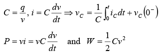
Circuit element: Capacitance
Differential Equations
Type I-(First order Homogeneous Differential Equation)
 where P is any constant
 take k ' =ln k ⇒ ln y(t) = −Pt + ln k
⇒ y(t) = ke−Pt where k is a constant
Type II-(First order Non Homogeneous Differential Equation)
 where P is a constant and Q may be a function of independent variable
t or a constant.


If Q is constant, then

Initial Conditions in Circuits
Number of initial conditions required is equal to the order of the differential equation for an unique solution.


Transient Response of Series R-L Circuit having DC Excitation
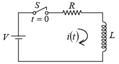
If switch S is closed at t = 0 . Then the current through the circuit is i (t ) . Applying KVL around the loop, we will get
Now L behaves as open circuit (O.C.) at switching,
Thus


New Transient Condition
As circuit reaches at steady state (at t = ∞ ), suddenly switch is open and new condition at t = 0 is shown.
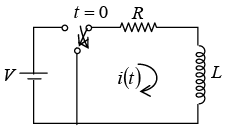
Now
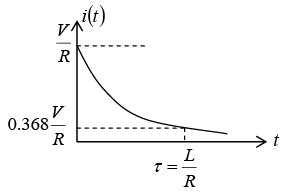
at t = 0+ , the inductor keep the steady state

Thus
Corresponding voltages across the resistor and inductor are
 Transient Response of Series R-C Circuit having DC Excitation
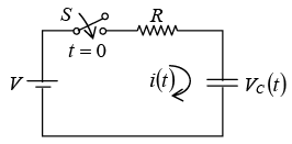
If switch S is closed at t = 0 . Then the current through the circuit is i (t ) . Applying KVL around the loop, we will get 
Initially capacitor was uncharged (0−) = 0
Differentiating above equation, we will get
At


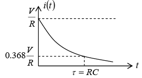
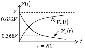
New Transient Condition
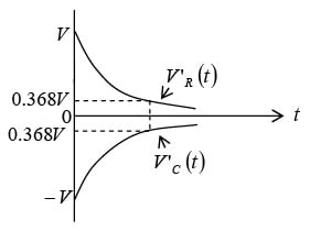
As circuit reaches at steady state (at t = ∞ ), suddenly switch is open and new condition t = 0 is shown.
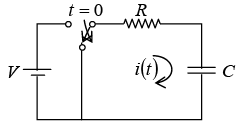
Now


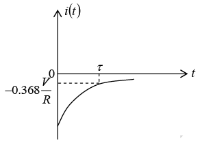
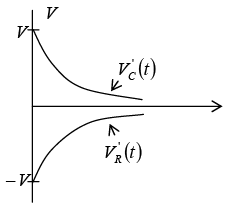
Transient Response of Series RLC Circuit having DC Excitation
Consider series RLC circuit VS = 2V , L =2H , R = 6 Ω and C = 0.25F . At t = 0 switch S is closed then in the transient state find current i(t ).
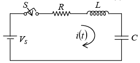
Applying KVL,


⇒ p2 + 3p + 2 = 0 ⇒ p1 = −1, p2 = − 2
⇒ i(t) = k1e−t + k2e−2 ………………… (3)
At t = 0 , i (0+) =0 (inductor is open circuited)
⇒ k1 + k2 = 0
From (1)

Thus
k1 = 1, k2 = -1
⇒ i(t)= e−t − e−2t
and From (2)
Transient Response of Parallel RLC Circuit having DC Excitation
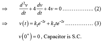
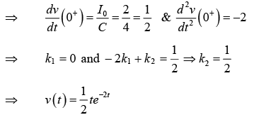
Consider Parallel RLC circuit I0 = 2A, L = 1/16H, R = 1/16 Ω and C = 4F . At t = 0 switch is closed then in the transient state find voltage v(t ).
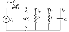 Applying KCL,
|
82 videos|32 docs|22 tests
|
FAQs on Simple DC circuits with R, L & C components - Electricity & Magnetism - Physics
| 1. What are the basic components of a DC circuit with R, L, and C elements? |  |
| 2. What is the role of a resistor in a DC circuit? |  |
| 3. How does an inductor behave in a DC circuit? |  |
| 4. What is the function of a capacitor in a DC circuit? |  |
| 5. How does the presence of R, L, and C components affect the behavior of a DC circuit? |  |

 Transient Response of Series R-C Circuit having DC Excitation


