Mechanical Engineering Exam > Mechanical Engineering Notes > Theory of Machines (TOM) > Study Notes for Gears
Study Notes for Gears | Theory of Machines (TOM) - Mechanical Engineering PDF Download
Gears
Gears are used to transmit motion from one shaft to another or between a shaft and slide. It is a higher pair mechanism. Gear use to intermediate link or connector and transmit the motion by direct contact.
Gears is a positive drive which transmits exact velocity ratio from one shaft to another shaft, gear drive is used when the distance between driver and follower is very less.
Gear Terminology
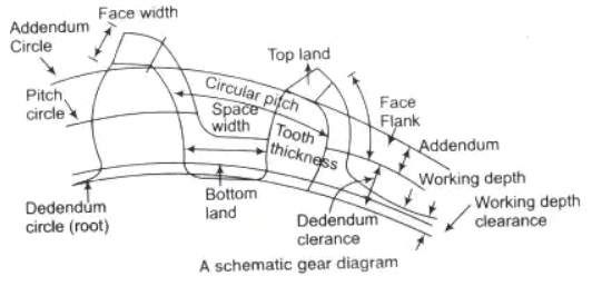
- Circular Pitch (p): It is a distance measured along the circumference of the pitch circle from a point on one tooth to the corresponding point on the adjacent tooth.
p = πd/T
where, p = circular pitch
d = pitch diameter
T = number of teeth
- Diametrical Pitch (P): It is the number of teeth per unit length of the pitch circle diameter in inches.
P = T/d - Module (m): It is the ratio of pitch diameter in mm to the number of teeth. The term is used SI units in place of diametrical pitch.
m = d/T
⇒ p = πm - Gear Ratio (G): It is the ratio of the number of teeth on the gear to that on the pinion.
G = T/t
where, T = number of teeth on the gear
t = number of teeth on the pinion - Velocity Ratio: The velocity ratio is defined as the ratio of the angular velocity of the follower to the angular velocity of the driver gear.

- Addendum Circle: A circle bounding the ends of the teeth, in a normal section of the gear.
- Dedendum Circle: The circle bounding the spaces between the teeth, in a normal section of the gear.
- Addendum: The radial distance between the pitch circle and the addendum circle.
- Dedendum: The radial distance between the pitch circle and the root circle,
- Standard Proportions: The following standard proportions are used in 20° full depth system
(i) Addendum ha = m
(ii) Clearance C = 0.25 m
(iii) Whole depth h = 2.25 m
(iv) Tooth space = 1.5700 m
(v) Dedendum hf = 1.25 m
(vi) Working depth hk = 2m
(vii) Tooth thickness (s) = 1.5708 m
(viii) Fillet radius = 0.4 m - Form of Teeth: The form of teeth in a gear system can be as follows.
- Conjugate Teeth: Two curves of any arbitrary shape that fulfill the law of gearing can be used as the profiles of teeth. Such a gear The profiles of tooths which are generally used given as
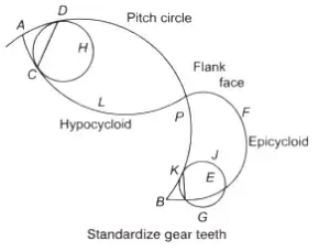
- Cycloidal Profile Teeth: As cycloid is the locus of a point on the circumference of a circle that rolls without slipping on a fixed straight line In this type, the faces of the teeth are epicycloids and the flanks the hypocycloids.
- Epicycloid Teeth: An epicycloid is the locus of point on the circumference of a circle that rolls without slipping on a fixed straight line.
Arc PK = arc KJG
- Hypocycloid Teeth: A hypocycloid is the locus of a point on the circumference of a circle that rolls without slipping inside the circumference of another circle.
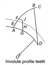
Arc AC = Arc CD - Involute Profile Teeth: An involute is defined as the locus of a point on a straight line which rolls without slipping on the circumference of a circle. From figure at the start the tracing point is at A as the rolls on the circumference of the circle, the path ABC traced out by the point A is the involute.
 D is regarded as the instantaneous centre of rotation of B. The motion of B is perpendicular to BD. Since, BD is tangent to the base circle, the normal to the involute is a tangent to the base circle.
Comparison between Cycloidal Teeth and Involute Teeth
- Cyclodial Teeth
(i) Pressure angle maximum at beginning of engagement, then reduce to zero at pitch
(ii) point and again maximum at end of engagement.
(iii) Less smooth running of gears.
(iv) Involve double curve, epicycloid and hypocycloid for the teeth
(v) Costier manufacturing
(vi) Exact centre distance is reuired to transmit a constant velocity ratio.
(vii) Phenomenon of interference does not occur at all.
(viii) Spreading flank teeth and strong.
(ix) Convex flank always has contact with a concave face resulting in less wear. - Involute Teeth
(i) Pressure angle is constant throughtout the engagement of teeth.
(ii) Smooth running of gears.
(iii) Involve single curve
(iv) Cheaper manufacturing
(v) A little variation in centre distance does not effect the velocity ratio
(vi) Interference can occur if the condition of minimum number of teeth on a gear is not followed.
(vii) Raidal flank teeth and weaker compare to cycloidal.
(viii) Two convex surfaces are in contact and thus there is more wear.
Methods of Gear Manufacturing
- Casting, blanking, machining.
- For power transmitting gears (made of steel), the following methods generally used are milling, rack generation, hobbing, fellow gear shaper method.
- For good accuracy and surface finish following finishing process are used grinding, lapping, sharing, barnishing.
The followings are the parameters used in manufacturing of gears as:
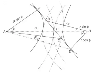
- Path of Contact (CD): According to the figure, the path of the contact is given by the relation
CD = CP + PD
= (CF - PE) + (DE - PE)
 Path of contact diagramwhere, r = pitch circle radius of pinion
R = pitch circle radius of wheel
ra = addendum circle radius of pinion
Ra = Addendum circle radius of wheel - Arc of Contact: From the figure, the arc of the contact as given by


Angle of action δp = arc of contact x (360/2pr) - Interference in Involute Gear
(i) Meshing of two non-conjugate (non-involute) teeth is known as interference because the two teeth do not slide properly and thus rough action and binding occurs.
(ii) For equal addenda of the wheel and pinion, the addendum radius of the wheel decides whether the interference will occur or not. - Minimum Number of Teeth
(i) Maximum value of the addendum radius of wheel to avoid interference can be upto BE
(BE)2 = (BF)2 + (FE)2
- Addendum value of wheel

where, G = gear ratio = (T/t)
T and t are number of teeth on the wheel and pinion respectively.
When addendum is equal to one module A = 1m
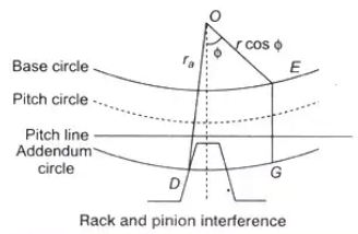
- Interference between Rack and Pinion: The interference between rack and pinion is shown in the figure.
 To avoid interference GE ≥ mAr
 For standard addendum,
To eliminate interference, there are following methods:
- By using more teeth on gears (however, it can make gear noiser).
- By larger pressure angle.
- By using gears with shorter teeth.
- To eliminate the undercutting or interference, the pinion addendum may be enlarged until the addendum circle of the pinion passes through the interference point of gear.
(i) Undercutting: When gear teeth are produced such that interference is eliminated then this effect is called undercutting.
(ii) Long and Short addendum System: In the long and short addendum system, there is no change in pitch circle and consequently not in pressure angle. The pinion addendum enlarge until the addendum circle of the pinion passes through the point of gear. In long and short addendum system, recess action is obtained more than approach action.
The document Study Notes for Gears | Theory of Machines (TOM) - Mechanical Engineering is a part of the Mechanical Engineering Course Theory of Machines (TOM).
All you need of Mechanical Engineering at this link: Mechanical Engineering
|
87 videos|43 docs|29 tests
|
FAQs on Study Notes for Gears - Theory of Machines (TOM) - Mechanical Engineering
| 1. What are gears used for in mechanical engineering? |  |
Ans. Gears are used in mechanical engineering to transmit motion and power between rotating shafts. They provide a way to change the speed, torque, and direction of rotation in a system.
| 2. What are the different types of gears used in mechanical engineering? |  |
Ans. There are several types of gears used in mechanical engineering, including spur gears, helical gears, bevel gears, worm gears, and planetary gears. Each type has its own unique characteristics and applications.
| 3. How do gears work in a mechanical system? |  |
Ans. Gears work by meshing together, with the teeth of one gear fitting into the gaps between the teeth of another gear. As one gear rotates, it transfers motion and power to the other gear, causing it to rotate as well. This allows for the transmission of motion and power between different parts of a mechanical system.
| 4. What factors should be considered when designing gears in mechanical engineering? |  |
Ans. When designing gears in mechanical engineering, factors such as load capacity, speed, tooth profile, material selection, lubrication, and noise level need to be considered. These factors ensure that the gears can effectively transmit power and motion while operating smoothly and efficiently.
| 5. How can gear failure be prevented in mechanical engineering systems? |  |
Ans. Gear failure in mechanical engineering systems can be prevented by proper design, material selection, lubrication, and maintenance. It is important to ensure that the gears are designed to handle the anticipated loads and speeds, use appropriate materials for the application, have proper lubrication to reduce wear and friction, and undergo regular inspection and maintenance to detect and address any potential issues before they lead to failure.
Related Searches


 D is regarded as the instantaneous centre of rotation of B. The motion of B is perpendicular to BD. Since, BD is tangent to the base circle, the normal to the involute is a tangent to the base circle.


 To avoid interference GE ≥ mAr
 For standard addendum,


