Superposition & Stationary Waves | Physics for Grade 12 PDF Download
| Table of contents |

|
| Graphical Representation of Superposition |

|
| Interference |

|
| Two-Source Interference |

|
| Young Double-Slit Experiment |

|
| Determining the Wavelength of Light |

|
| Stationary Waves |

|
The Principle of Superposition
- The principle of superposition states:
- When two or more waves with the same frequency arrived at a point, the resultant displacement is the sum of the displacements of each wave
- The waves often travel in opposite directions because they're reflected at a boundary
- This principle describes how waves that meet at a point in space interact
Superposition Experiments
- Superposition experiments include using sound, light and microwaves
Sound
- Superposition creates stationary, longitudinal sound waves in a resonance tube such as in an organ pipe or woodwind instruments such as a flute
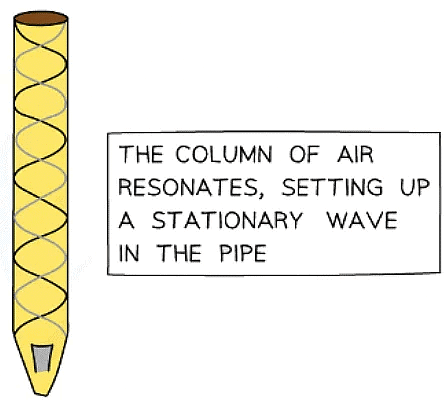
- Superposition experiments with sound often use air columns or speakers
- If two loudspeakers are connected to the same signal generator, the superposition of the sound waves can be heard when walking along in front of the speakers
- A loud sound is heard when the sound waves reinforce one another
- A quiet or no sound is heard when the waves cancel each other out
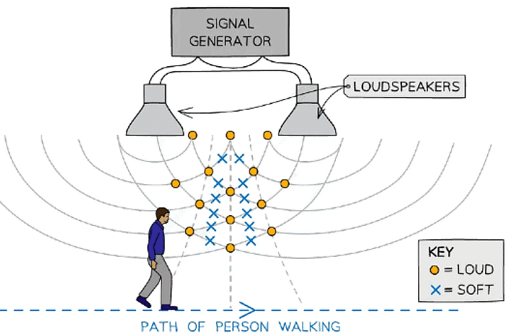
The superposition of sound waves can be detected by the person walking past hearing a loud and soft sound in intervals
Light
- The superposition of light waves is demonstrated through:
- Young's double-slit experiment
- Diffraction grating
- The light waves are superposed when they reach a screen
- This shows an interference pattern
- Monochromatic laser light is commonly used for these experiment to produce the clearest interference pattern on the screen
- The distance between the maxima and minima on the pattern varies with the frequency of the light (colour)
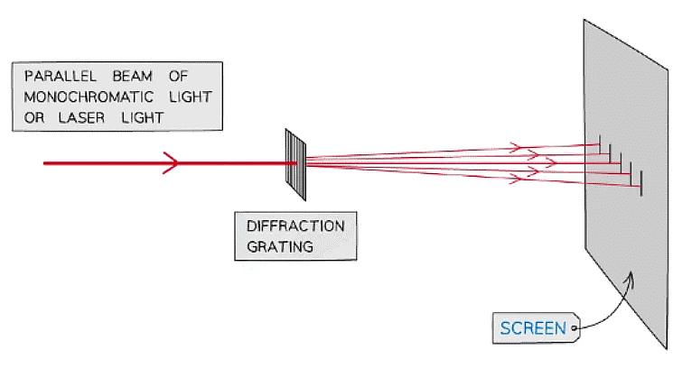
An example of an experiment that demonstrates superposition is light passing through a diffraction grating
Microwaves
- Similar to light and sound, microwaves also superpose to create regions where the microwaves reinforce or cancel each other out
- The interference of microwaves creates a standing wave inside a microwave oven, which is used to heat food
- Microwave superposition experiments normally include:
- Two microwave transmitters
- A microwave detector
- To produce a microwave stationary wave, a microwave reflector is often used too, with just one transmitter
Graphical Representation of Superposition
- Superposition can be represented graphically
- When two waves superpose, the wave seen is the resultant wave of them both
- This is the principle of superposition
- Complete constructive or destructive interference is seen most clearly when the two superposing wave have the same speed, frequency and amplitude
- Although, any two waves, whether they are both longitudinal or transverse, can superpose
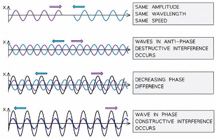
- Although, any two waves, whether they are both longitudinal or transverse, can superpose
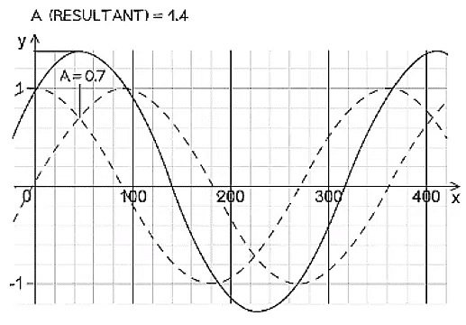
A graphical representation of how superposition - the black line represents the resulting wave
Example: Two overlapping waves of the same types travel in the same direction. The variation with x and y displacement of the wave is shown in the figure below.
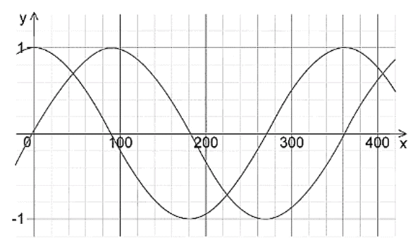
Use the principle of superposition to sketch the resultant wave.
The graph of the superposition of both waves is shown in black below:
To plot the correct amplitude at each point, sum the amplitude of both graphs at that point.
e.g. at point a — each graph has a value of 0.7. therefore the same point with the resultant superposition is 0.7 x 2 = 1.4
Interference
- Interference occurs when waves overlap and their resultant displacement is the sum of the displacement of each wave
- This result is based on the principle of superposition
- The resultant waves may be smaller or larger than either of the two individual waves
- When two waves with the same frequency and amplitude arrive at a point, they superpose either:
- In phase, causing constructive interference. The peaks and troughs line up on both waves and the resultant wave has double the amplitude
- In anti-phase, causing destructive interference. The peaks on one wave line up with the troughs of the other. The resultant wave has no amplitude
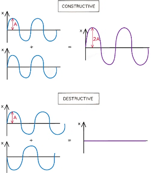
Waves in superposition can undergo constructive or destructive interference
- The principle of superposition applies to all types of waves i.e. transverse and longitudinal, progressive and stationary
Coherence
- At points where the two waves are neither in phase nor in antiphase, the resultant amplitude is somewhere in between the two extremes
- Waves are said to be coherent if they have:
- The same frequency
- A constant phase difference
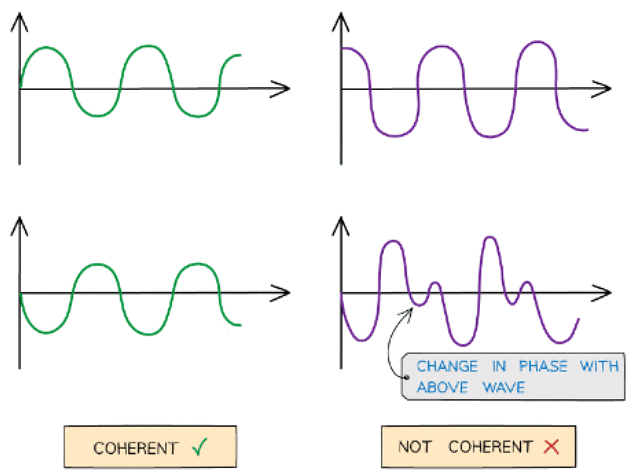
Coherent v non-coherent wave. The abrupt change in phase creates an inconsistent phase difference
- Coherence is vital in order to produce an observable, or hearable, interference pattern
- Laser light is an example of a coherent light source, whereas filament lamps produce incoherent light waves
- When coherent sound waves are in phase, the sound is louder because of constructive interference
Path Difference
- Path difference is defined as:
- The difference in distance travelled by two waves from their sources to the point where they meet
- Path difference is generally expressed in multiples of α wavelength
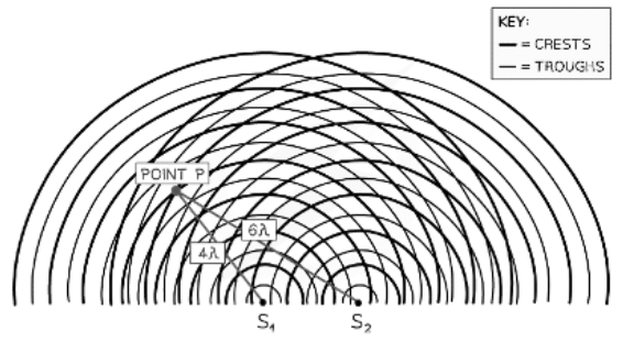
At point P the waves have a path difference of a whole number of wavelengths resulting in constructive interference
- Another way to represent waves spreading out from two sources is shown in the diagram above
- At point P, the number of crests from:
- Source S1 = 4λ
- Source S2 = 6λ
- The path difference at P is 6λ – 4λ = 2λ
Phase Difference
- Two waves with a path difference will also have a difference in phase
- This is their phase difference
- Phase difference is defined as:
- The difference in phase between two waves that arrive at the same point
- It is given as an angle, in radians or degrees
Constructive & Destructive Interference
- Whether two waves will constructively or destructively interfere at a point is determined by its path difference or phase difference
Path Difference
- Path difference is determined in multiples of a wavelength
- Constructive interference occurs when there is a path difference of nλ
- For example, 2λ
- Destructive interference occurs when there is a path difference of (n + ½)λ
- For example, 3λ / 2 or 1.5λ
- In this case, n is an integer i.e. 1, 2, 3...
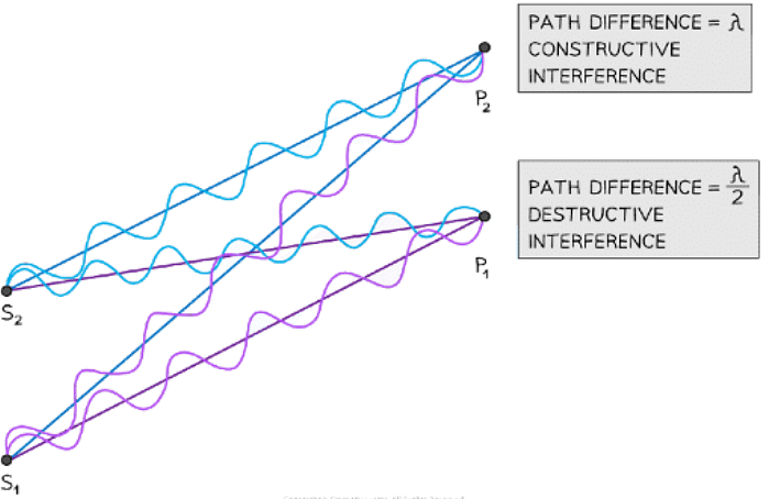
At point P2 the waves have a path difference of a whole number of wavelengths resulting in constructive interference. At point P1 the waves have a path difference of an odd number of half wavelengths resulting in destructive interference
- In the diagram above, the number of wavelengths between:
- S1 ➜ P1 = 6λ
- S2 ➜ P1 = 6.5λ
- S1 ➜ P2 = 7λ
- S2 ➜ P2 = 6λ
- The path difference at point P1 is 6.5λ – 6λ = λ / 2
- Therefore, this is destructive interference (half-wavelength difference)
- The path difference at point P2 is 7λ – 6λ = λ
- Therefore, this is constructive interference (a whole number of wavelengths difference)
Phase Difference
- The phase difference between two waves is determined by an angle, in radians or degrees
- Constructive interference occurs when the phase difference is an even multiple of π or that they are in phase
- Eg. 2π, 4π
- Destructive interference occurs when the phase difference is an odd multiple of π or that they are in anti-phase
- Eg. π, 3π
Example: The diagram shows the interferences of coherent waves from two point sources.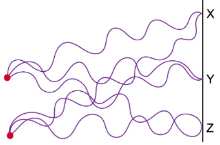
Which row in the table correctly identifies the type of interference at points X, Y and Z.
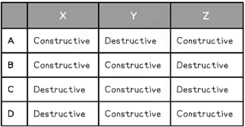
Ans. b
At point X:
- Both peaks of the waves are overlapping
- Path difference = 5.5λ – 4.5λ = λ
- This is constructive interference and rules out options C and D
At point Y:
- Both troughs are overlapping
- Path difference = 3.5λ – 3.5λ = 0
- Therefore constructive interference occurs
At point Z:
- A peak of one of the waves meets the trough of the other
- Path difference = 4λ – 3.5λ = λ / 2
- This is destructive interference
Two-Source Interference
- Two-source interference can be demonstrated using sound and microwaves
Using Sound Waves
- Sound waves are longitudinal waves so are made up of compressions and rarefactions
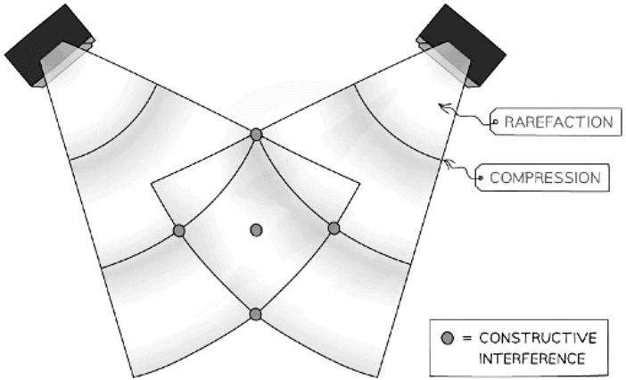
Sound wave interference from two speakers
- Constructive interference occurs when two compressions or two rarefactions line up and the sound appears louder
- Destructive interference occurs when a compression lines up with a rarefaction and vice versa. The sound is quieter
- This is the technology used in noise-cancelling headphones
Using Microwaves
- Two source interference for microwaves can be detected with a moveable microwave detector
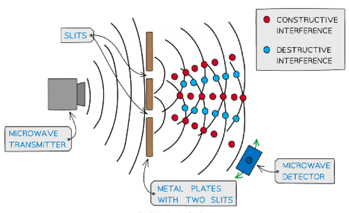
Microwave interference experiment
- Constructive interference occurs in regions where the detector picks up a maximum amplitude of the signal
- Destructive interference occurs in regions where the detector picks up no signal
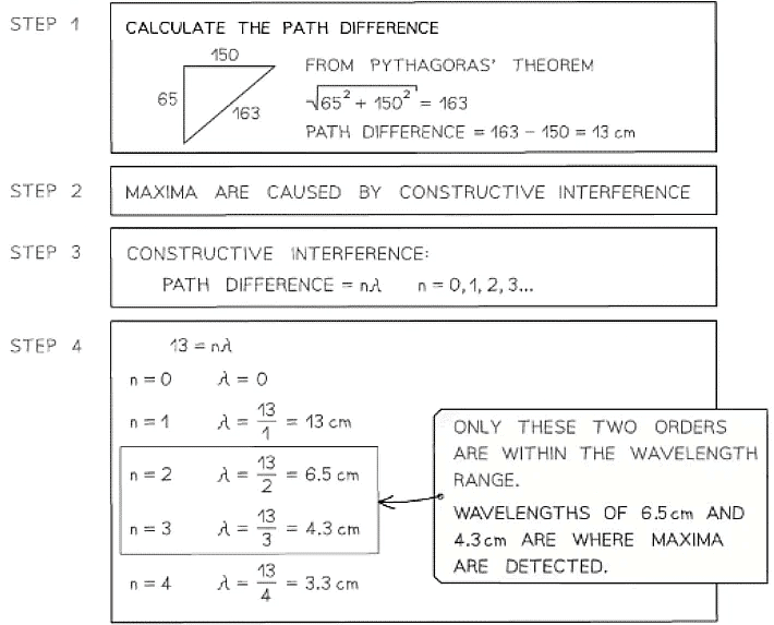
Example: Two coherent sources of sound waves S1 and S2 are situated 65 cm apart in air as shown below.
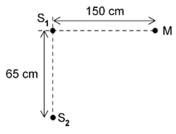 The two sources vibrate in phase but have different amplitudes of vibration. A microphone M is situated 150 cm from S1 along the line normal to S1 and S2.The microphone detects maxima and minima of the intensity of the sound. The wavelength of the sound from S1 to S2 is decreased by increasing the frequency. Determine which orders of maxima are detected at M as the wavelength is increased from 3.5 cm to 12.5 cm.
Young Double-Slit Experiment
- For two-source interference fringes to be observed, the sources of the wave must be:
- Coherent (constant phase difference)
- Monochromatic (single wavelength)
- When two waves interfere, the resultant wave depends on the phase difference between the two waves
- This is proportional to the path difference between the waves which can be written in terms of the wavelength λ of the wave
- As seen from the diagram, the wave from slit S2 has to travel slightly further than that from S1 to reach the same point on the screen
- The difference in this distance is the path difference
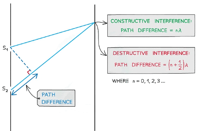
- The difference in this distance is the path difference
Path difference of constructive and destructive interference is determined by wavelength
- For constructive interference (or maxima), the difference in wavelengths will be an integer number of whole wavelengths
- For destructive interference (or minima) it will be an integer number of whole wavelengths plus a half wavelength
- n is the order of the maxima/minima since there is usually more than one of these produced by the interference pattern
- An example of the orders of maxima is shown below:
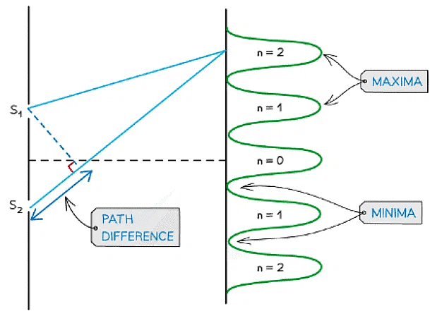
Interference pattern of light waves shown with orders of maxima
- n = 0 is taken from the middle, n = 1 is one either side and so on
Young's Double Slit Experiment
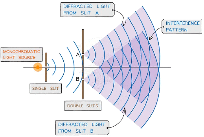 Young’s double-slit experiment arrangement
- When a monochromatic light source is placed behind a single slit, the light is diffracted producing two light sources at the double slits A and B
- Since both light sources originate from the same primary source, they are coherent and will therefore create an observable interference pattern
- Both diffracted light from the double slits create an interference pattern made up of bright and dark fringes
Wave Nature of Light
- Interference is a confirmation of the wave-nature of light
- Newton initially proposed that visible light is a stream of microscopic particles called corpuscles
- However, these corpuscles could not explain interference or diffraction effects, therefore, the view of light as a wave was adopted instead
- Not long after, Huygens came up with the original Wave Theory of Light to explain the phenomena of diffraction and refraction
- This theory describes light as a series of wavefronts on which every point is a source of waves that spread out and travel at the same speed as the source wave
- These are known as Huygens’ wavelets
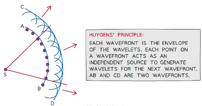
Huygen's wavelets shown by two wavefronts AB and CD
Double-Slit Equation
- The fringe width, wavelength of the light, distance between the slits or the distance from the slits to the screen can be calculated using the double-slit equation:
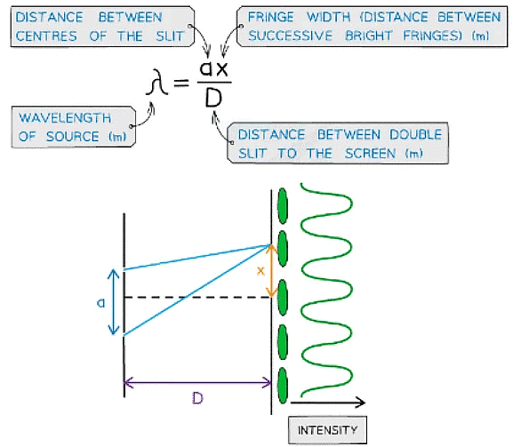
- This equation is only when a << D
- The interference pattern on a screen will show as ‘fringes’ which are dark or bright bands
- Constructive interference is shown through bright fringes with varying intensity (most intense in the middle)
- Destructive interference is shown from dark fringes where no light is seen
- A monochromatic light source makes these fringes clearer and the distance between fringes is very small due to the short wavelength of visible light
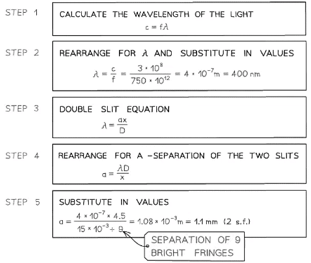
Example: A laser is placed in front of a double-slit as shown in the diagram below.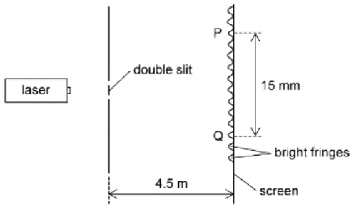 The laser emits light of frequency 750 THz. The separation of the maxima P and Q observed on the screen is 15 mm. The distance between the double slit and the screen is 4.5 m.
Determining the Wavelength of Light
Equipment List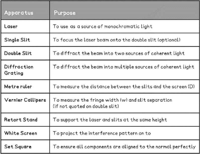
- Resolution of measuring equipment:
- Metre ruler = 1 mm
- Vernier Callipers = 0.01 mm
Young’s Double-Slit Experiment
The overall aim of this experiment is to investigate the relationship between the distance between the slits and the screen, D, and the fringe width, w
- Independent variable = Fringe width, w
- Dependent variable = Distance between the slits and the screen, D
- Control variables
- Laser wavelength, λ
- Slit separation, s
Method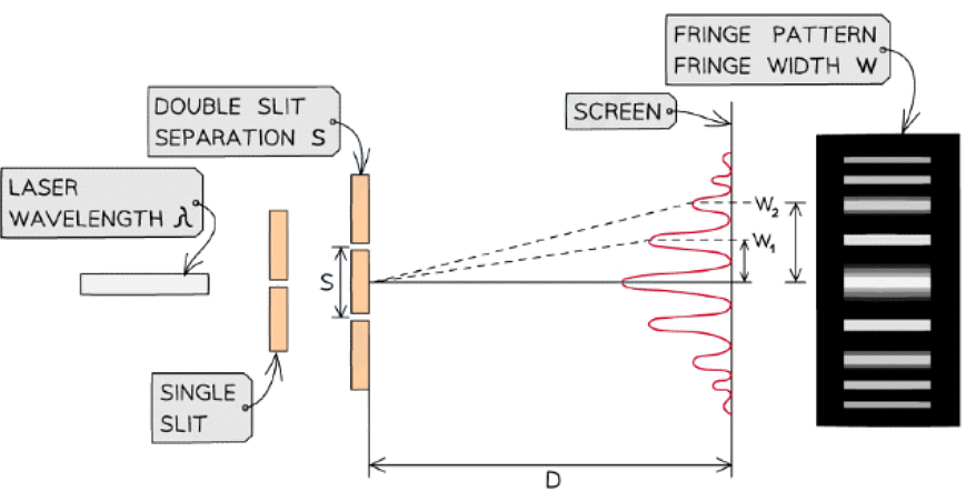
The setup of apparatus required to measure the fringe width w for different values of D
- Set up the apparatus by fixing the laser and the slits to a retort stand and place the screen so that D is 0.5 m, measured using the metre ruler
- Darken the room and turn on the laser
- Measure from the central fringe across many fringes using the vernier callipers and divide by the number of fringe widths to find the fringe width, w
- Increase the distance D by 0.1 m and repeat the procedure, increasing it by 0.1 m each time up to around 1.5 m
- Repeat the experiment twice more and calculate and record the mean fringe width w for each distance D
An example table might look like this: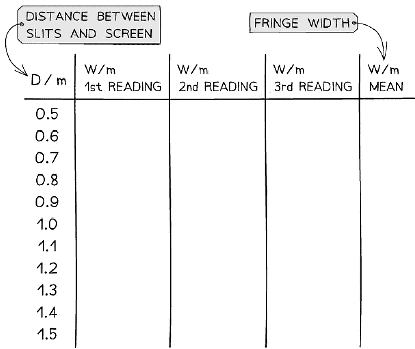
Analysing the Results
- The fringe spacing equation is given by:
w = λD/s - Where:
- w = the distance between each fringe (m)
- λ = the wavelength of the laser light (m)
- D = the distance between the slit and the screen (m)
- s = the slit separation (m)
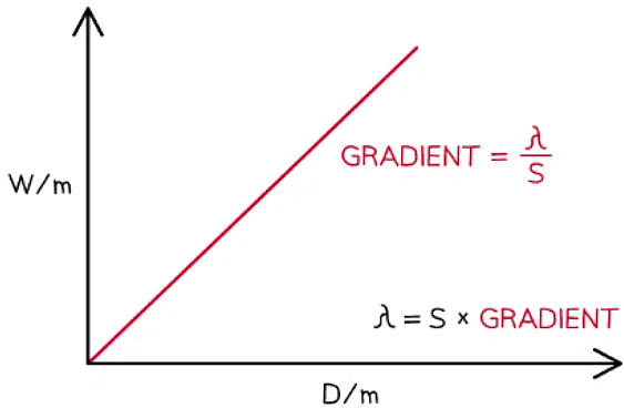
- Comparing this to the equation of a straight line: y = mx
- y = w (m)
- x = D (m)
- Gradient = λ / s (unitless)
- Plot a graph of w against D and draw a line of best fit
- The wavelength of the laser light is equal to the gradient multiplied by the slit separation
Interference by a Diffraction Grating
The overall aim of this experiment is to calculate the wavelength of the laser light using a diffraction grating
- Independent variable = Distance between maxima, h
- Dependent variable = The angle between the normal and each order, θn (where n = 1, 2, 3 etc)
- Control variables
- Distance between the slits and the screen, D
- Laser wavelength λ
- Slit separation, d
Method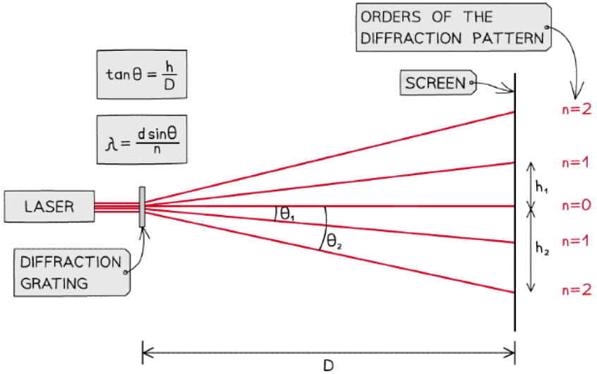
The setup of apparatus required to measure the distance between maxima h at different angles θ
- Place the laser on a retort stand and the diffraction grating in front of it
- Use a set square to ensure the beam passes through the grating at normal incidence and meets the screen perpendicularly
- Set the distance D between the grating and the screen to be 1.0 m using a metre ruler
- Darken the room and turn on the laser
- Identify the zero-order maximum (the central beam)
- Measure the distance h to the nearest two first-order maxima (i.e. n = 1, n = 2) using a vernier calliper
- Calculate the mean of these two values
- Measure distance h for increasing orders
- Repeat with a diffraction grating with a different number of slits per mm
An example table might look like this: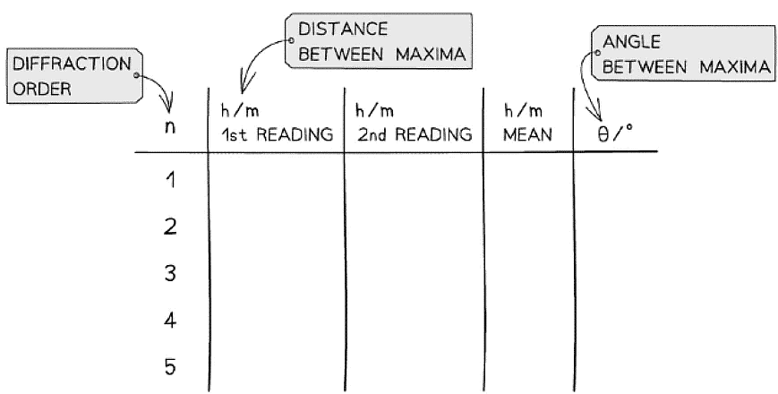
Analysing the Results
The diffraction grating equation is given by:
- nλ = d sin θ
Where:
- n = the order of the diffraction pattern
- λ = the wavelength of the laser light (m)
- d = the distance between the slits (m)
- θ = the angle between the normal and the maxima
The distance between the slits is equal to:
- d = 1/N
Where
- N = the number of slits per metre (m–1)
Since the angle is not small, it must be calculated using trigonometry with the measurements for the distance between maxima, h, and the distance between the slits and the screen, D
Calculate a mean θ value for each order
Calculate a mean value for the wavelength of the laser light and compare the value with the accepted wavelength
- This is usually 635 nm for a standard school red laser
Evaluating the Experiments
- Systematic errors:
- Ensure the use of the set square to avoid parallax error in the measurement of the fringe width
- Using a grating with more lines per mm will result in greater values of h. This lowers its percentage uncertainty
- Random errors:
- The fringe spacing can be subjective depending on its intensity on the screen, therefore, take multiple measurements of w and h (between 3-8) and find the average
- Use a Vernier scale to record distances w and h to reduce percentage uncertainty
- Reduce the uncertainty in w and h by measuring across all visible fringes and dividing by the number of fringes
- Increase the grating to screen distance D to increase the fringe separation (although this may decrease the intensity of light reaching the screen)
- Conduct the experiment in a darkened room, so the fringes are clear
Safety Considerations
- Lasers should be Class 2 and have a maximum output of no more than 1 mW
- Do not allow laser beams to shine into anyone’s eyes
- Remove reflective surfaces from the room to ensure no laser light is reflected into anyone’s eyes
Example: A student investigates the interference patterns produced by two different diffraction gratings. One grating used was marked 100 slits / mm, the other was marked 300 slits / mm. The distance between the grating and the screen is measured to be 3.75 m.The student recorded the distance between adjacent maxima after passing a monochromatic laser source through each grating. These results are shown in the tables below.

Calculate the mean wavelength of the laser light and compare it with the accepted value of 635 nm. Assess the percentage uncertainty in this result.
Step 1: Calculate the distance between the slits
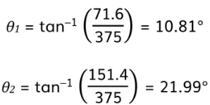
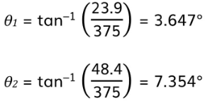
Step 2: Calculate the mean angle for each orderθ = tan-1(h/D)
- For 300 slits/mm:
- For 100 slits/mm:
Step 3: Use the grating equation to determine the wavelengths for each order
nλ = d sin θ
- For 300 slits/mm:
- For 100 slits/mm:
Step 4: Calculate the mean wavelenght
Step 5: determine the percentage uncertainty in this value
- The difference between the calculated and accepted value is:
635 - 631 = 4 nm
% uncertainty = 4/635 x 100 % = 0.6%
Stationary Waves
- Stationary waves, or standing waves, are produced by the superposition of two waves of the same frequency and amplitude travelling in opposite directions
- This is usually achieved by a travelling wave and its reflection
- The superposition produces a wave pattern where the peaks and troughs do not move
- Stationary waves store energy, unlike progressive waves which transfer energy
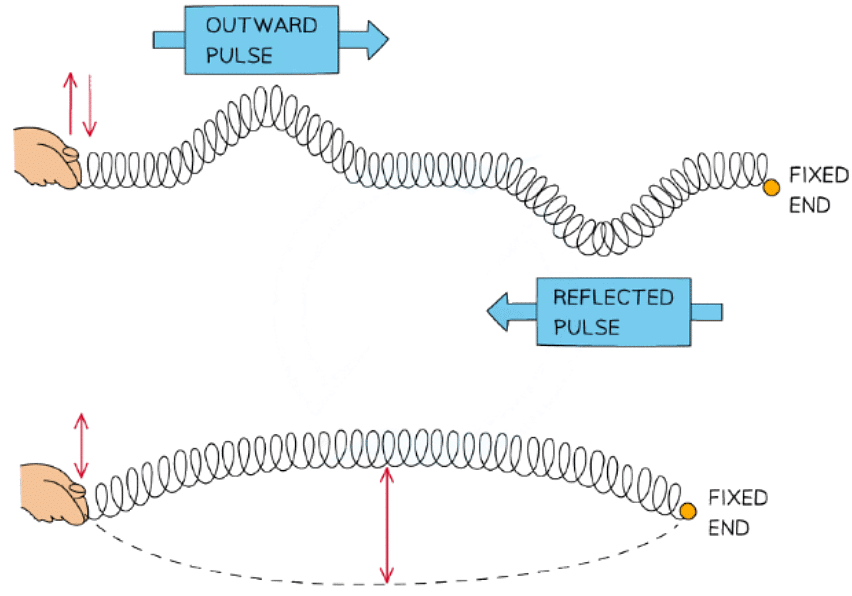
Formation of a stationary wave on a stretched spring fixed at one end
- Stationary waves can be represented by various mediums
Stretched String
- Vibrations caused by stationary waves on a stretched string produce sound
- This is how stringed instruments, such as guitars or violins, work
- This can be demonstrated by a length of string under tension fixed at one end and vibrations made by an oscillator:
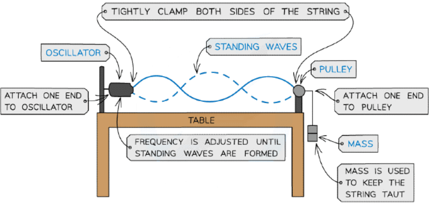
Stationary wave on a stretched string
- As the frequency of the oscillator changes, standing waves with different numbers of minima (nodes) and maxima (antinodes) form
Microwaves
- A microwave source is placed in line with a reflecting plate and a small detector between the two
- The reflector can be moved to and from the source to vary the stationary wave pattern formed
- By moving the detector, it can pick up the minima (nodes) and maxima (antinodes) of the stationary wave pattern
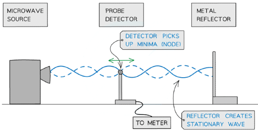
Using microwaves to demonstrate stationary waves
Air Columns
- The formation of stationary waves inside an air column can be produced by sound waves
- This is how musical instruments, such as clarinets and organs, work
- This can be demonstrated by placing a fine powder inside the air column and a loudspeaker at the open end
- At certain frequencies, the powder forms evenly spaced heaps along the tube, showing where there is zero disturbance as a result of the nodes of the stationary wave
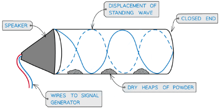
Stationary wave in an air column
- In order to produce a stationary wave, there must be a minima (node) at one end and a maxima (antinode) at the end with the loudspeaker
Graphical Representation of a Stationary Wave
- A stationary wave is formed when two waves travelling in opposite directions along the same line overlap with each other
- The waves must have:
- The same speed
- The same frequency (or wavelength)
- A similar amplitude
- As a result of superposition, a resultant wave is produced
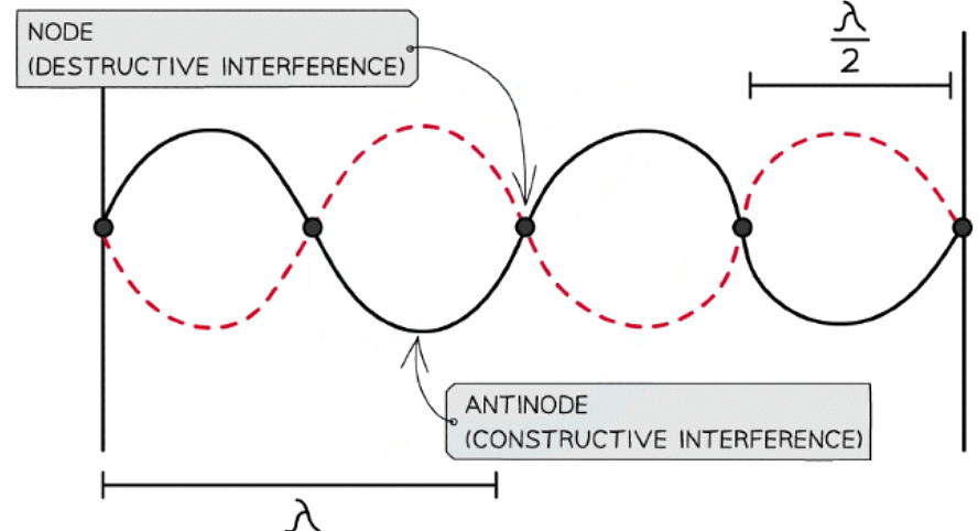
Nodes and antinodes are a result of destructive and constructive interference respectively
- A stationary wave is made up of nodes and antinodes
- At the nodes:
- The waves are in anti-phase meaning destructive interference occurs
- This causes the two waves to cancel each other out and there is no vibration
- At the antinodes:
- The waves are in phase meaning constructive interference occurs
- This causes the waves to add together and the vibration is at maximum amplitude
Stationary vs Progressive Waves
- There are both similarities and differences between progressive and stationary waves
- These are listed in the table below:
Comparing Progressive & Stationary Waves
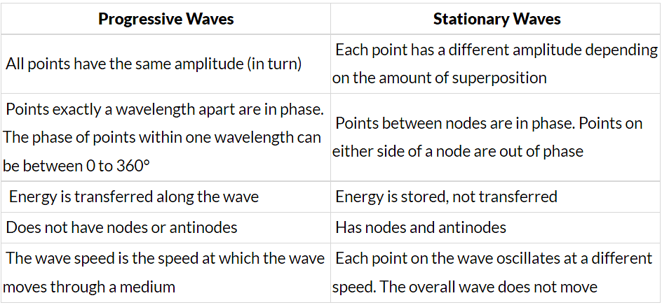
Nodes & Antinodes
- A stationary wave is made up nodes and antinodes
- Nodes are regions where there is no vibration
- Antinodes are regions where the vibrations are at their maximum amplitude
- The nodes and antinodes do not move along the string
- Nodes are fixed and antinodes only move in the vertical direction
- The phase difference between two points on a stationary wave are either in phase or out of phase
- Points between nodes are in phase with each other
- Points that have an odd number of nodes between them are out of phase
- Points that have an even number of nodes between them are in phase
- The image below shows the nodes and antinodes on a snapshot of a stationary wave at a point in time
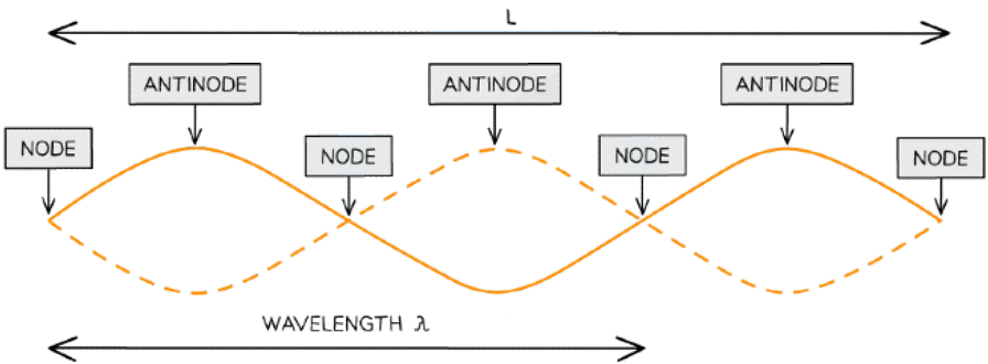
One wavelength on a stationary wave is only a proportion of its full length
- Where:
- L is the length of the string
- One wavelength λ is only a portion of the length of the string
Example: A stretched string is used to demonstrate a stationary wave, as shown in the diagram.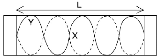
Which row in the table correctly describes the length of L and the name of X and Y?
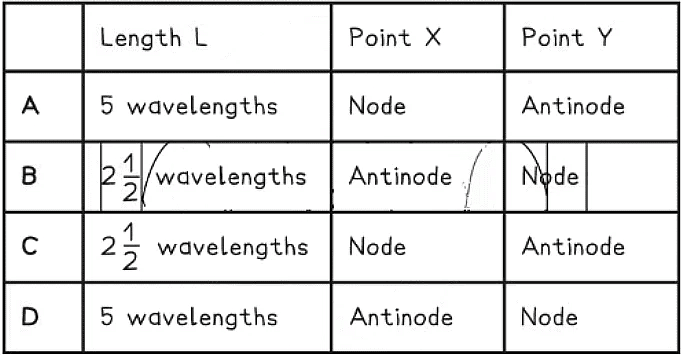
Ans. c
Step 1: Calculate how many wavelengths in the length of the string
Step 2: X is a point of 0 displacement
Step 3: Y is a point of maximum displacement - an antinode
Step 4: The correct row is c
Calculating Wavelength from Nodes & Antinodes
- The wavelength λ of a stationary wave can be determined by the separation between adjacent nodes (or antinodes)
- The separation between adjacent nodes or antinodes is equal to λ / 2
- Adjacent means two nodes or antinodes that are next to each other
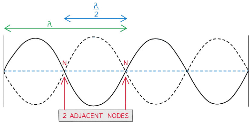
2 adjacent nodes are nodes that are directly next to each other
Example: The stationary wave below has a length L of 15 cm.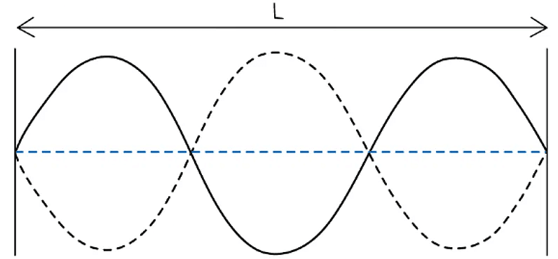 Calculate the wavelength λ of the wave.
Step 1: Calculate the distance between two nodes
- Distance between two nodes = 15 cm ÷ 3 = 5 cm
Step 2: Calculate λ
- Distance between two nodes = λ / 2 = 5 cm
- λ = 2 × 5cm = 10 cm
Determining the Speed of Sound in Air in a Resonance Tube
Aims of the Experiment
- The aim of the experiment is calculate the speed of sound in air using a tuning fork and a tube of water
Variables:
- Independent variable = Air level in the tube
- Dependent variable = Length of the air column in the tube where resonance occurs, L
- Control variables:
- Temperature of the water
- Frequency of the tuning fork
Equipment List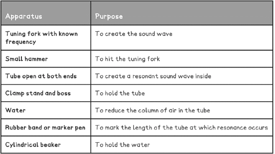
Method
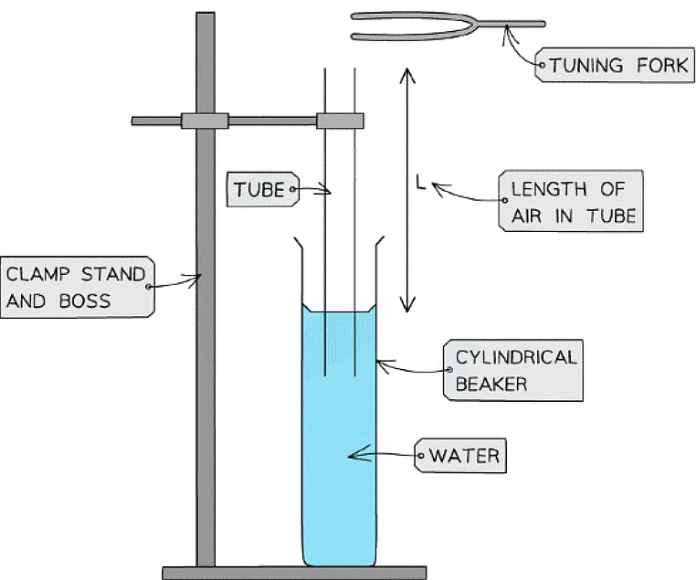
Apparatus setup to measure the speed of sound in a column of air
- Set up the equipment and fill up the beaker halfway with water
- Place the tube inside the beaker, so the water comes up a quarter of the way. The side of the tube in the water acts as a closed-end
- Hold the tuning fork above the open end of the tube and strike it lightly with the small hammer
- Slowly lower the tube into the water by loosening the clamp until the intensity of sound is amplified
- When resonance (loudest sound) is heard, mark the water level with a rubber band or marker pen. Record this as L1
- Then, lower the water further until the next point of resonance is heard and mark it. Record this as L2
- Keep going in this manner as far as possible
Analysis of Results
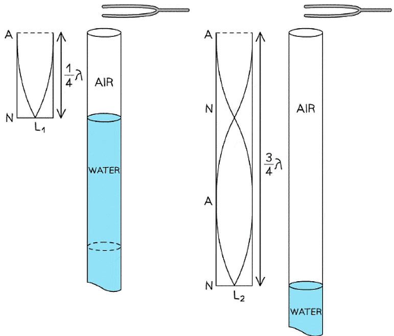 Standing waves in the air columns are used to calculate the wavelength of the sound waves
- Resonance should occur when the open tube length L is equal to λ / 4, 3λ / 4 and 5λ / 4
- The loudness of the sound in the tube from the fork will be small at the node of the sound wave
- The sound will be the loudest at the antinode of the sound wave
- At L1 the wavelength is λ / 4
- At L2 the wavelength is 3λ / 4
L2 – L1 = λ / 2 - Therefore, the wavelength of the sound λ is equal to:
λ = 2(L2 – L1) - Another value of λ could also be found from the distance between L3 and L2 and a mean wavelength can be calculate
- From the wave equation:
v = fλ - The speed of the sound wave, v, can found from the product of the frequency f of the tuning fork and the wavelength λ calculated
Evaluating the Experiment
Systematic Errors:
- The tuning fork should be struck at the same place above the tube each time
- The tuning fork should be struck with the same force each time
Random Errors:
- Make sure the marker is a thin line to get a more accurate reading of the water level
- Submerge the tube into the water slowly, so the antinode of the sound wave (loudest sound) is not missed
- Repeat the experiment to record more reliable readings, since the point where the sound is the loudest is subjective
- Using a resonance tube with a scale will help account for error when measuring the length of the air column within it
Safety Considerations
- Don't let the tuning fork touch the tube, since the vibrations could break or crack it
- Make sure the water is at room temperature, and not too hot or cold
- Make sure no electrical equipment is near the water, otherwise they could be damaged
Harmonics
- Stationary waves have different wave patterns depending on the frequency of the vibration and the situation in which they are created
Two Fixed Ends
- When a stationary wave, such as a vibrating string, is fixed at both ends, the simplest wave pattern is a single loop made up of two nodes and an antinode
- This is called the fundamental mode of vibration or the first harmonic
- The particular frequencies (i.e. resonant frequencies) of standing waves possible in the string depend on its length L and its speed v
- As the frequency is increased, the higher harmonics begin to appear
- The frequencies can be calculated from the string length and wave equation
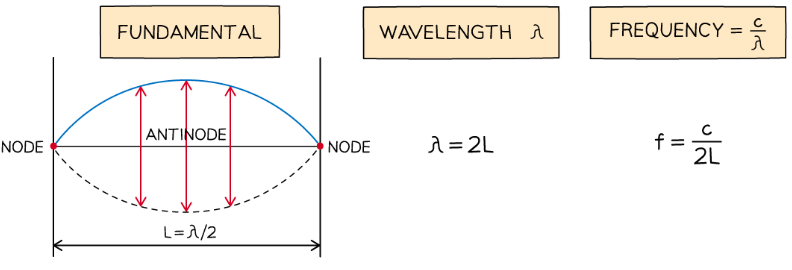
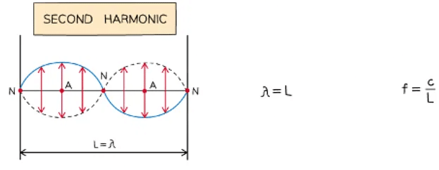
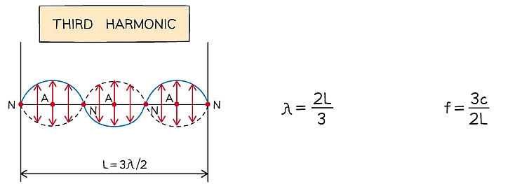
Diagram showing the first three modes of vibration of a stretched string with corresponding frequencies
- The nth harmonic has n antinodes and n + 1 nodes
One or Two Open Ends in an Air Column
- When a stationary wave is formed in an air column with one or two open ends, slightly different wave patterns are observed in each
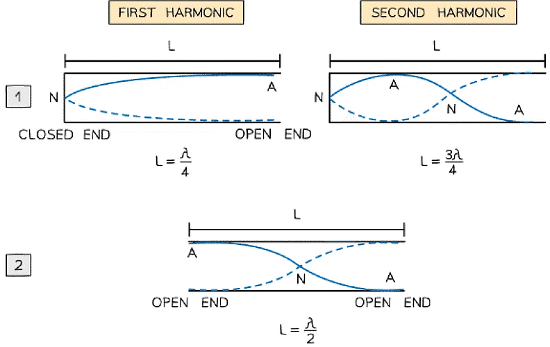
Diagram showing modes of vibration in pipes with one end closed and the other open or both ends open
- In Image 1: only one end of the air column is open, so, the fundamental mode is now made up of a quarter of a wavelength with one node and one antinode
- Every harmonic after that adds on an extra node or antinode
- In Image 2: the column is open on both ends, so, the fundamental mode is made up of one node and two antinodes
- In summary, a column length L for a wave with wavelength λ and resonant frequency f for stationary waves to appear is as follows:
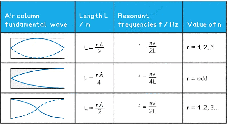
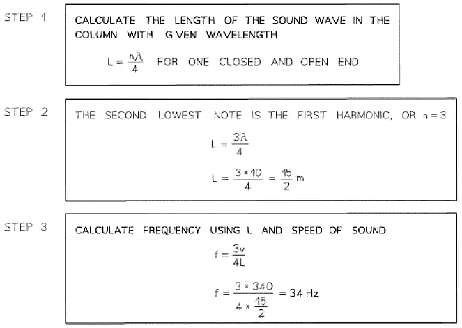
Example: A standing wave is set up in a loudspeaker emits sound with frequency f and is placed at one end of a pipe with length L. The pipe is closed at the other end.The speed of sound is 340 m s-1. With a sound wave of wavelength of 10 m, what is the frequency of the second lowest note produced?
|
142 videos|312 docs|132 tests
|

