Textbook Solution: Sequencing and pattern recognition: Getting the message Across | IGCSE Cambridge Computing for Year 7 - Class 7 PDF Download
Q1. Explain to a partner the purpose of a software prototype in a software-development project.
Ans :
Purpose of a Software Prototype in a Software Development Project
A software prototype serves as an early model of the final software, used to visualize and test the basic concepts and functionality. The main purposes of creating a software prototype include:
- Understanding Requirements: Helps stakeholders visualize the software, which clarifies and refines requirements.
- Testing Feasibility: Allows developers to test technical solutions and determine the feasibility of the design.
- Gathering Feedback: Provides a tangible product for users to interact with, facilitating early feedback and iterative improvements.
- Demonstrating Functionality: Showcases core functionality to stakeholders, which can be crucial for securing funding or approval.
Q2. Evaluate the following throwaway software prototype. It has been created for a light sequence on the micro:bit. The prototype is moving from a large square to a small square to a clear screen.
- Open the file LightSequence1.py provided by your teacher.
- Connect the micro:bit to t he device w it h the USB cable.
- Flash the program to the micro:bit to test it.
- Discuss these questions with a partner:
Can the images be recognised easily?
Are the images displayed for long enough to be seen clearly?
Do the images flow smoothly from one to another?
What improvements would you make?
Ans :
Evaluation of Throwaway Software Prototype (LightSequence1.py)
Steps to Evaluate:
- Open the file LightSequence1.py.
- Connect the micro to the device using a USB cable.
- Flash the program to the micro and test it.
Discussion Questions:
- Can the images be recognized easily?
- Evaluate if the large and small squares and the clear screen are distinct and easily identifiable.
- Are the images displayed for long enough to be seen clearly?
- Check if each image remains on the screen long enough to be recognized.
- Do the images flow smoothly from one to another?
- Assess if the transition between images is smooth and coherent.
Improvements:
- Adjust the display time for each image if they are too brief or too long.
- Ensure smooth transitions by refining the timing or sequence logic.
Q3: Evaluate the following evolutionary software prototype. It has been created for two light sequences on t he micro:bit. The software prototype displays:
a large diamond, small diamond then clear screen if the B button is pressed
a large square, small square and then clear screen if the A button is pressed .
- Open the file LightSequence2.py provided by your teacher.
- Connect the micro:bit to t he device with the USB cable.
- Flash the program to the micro:bit to test it.
- Discuss these questions with a partner:
Does the correct light display show when th e A or B button is pressed?
Can the images be recogn ised easily?
Are the images displayed for long enough to be seen clearly?
Do the images flow smoothly from one to another?
What improvements would you make?
Ans :
Evaluation of Evolutionary Software Prototype (LightSequence2.py)
Steps to Evaluate:
- Open the file LightSequence2.py.
- Connect the micro to the device using a USB cable.
- Flash the program to the micro and test it.
Discussion Questions:
- Does the correct light display show when the A or B button is pressed?
- Verify if pressing button A shows the large square, small square, and clear screen sequence, and button B shows the large diamond, small diamond, and clear screen sequence.
- Can the images be recognized easily?
- Ensure that the large and small shapes are easily distinguishable.
- Are the images displayed for long enough to be seen clearly?
- Check if the display duration is appropriate for recognition.
- Do the images flow smoothly from one to another?
- Evaluate the smoothness of transitions between images.
Improvements:
- Adjust display timings if images are not shown long enough.
- Refine the button press logic to ensure accurate sequence display.
- Enhance transitions for smoother visual flow.
Q4. What are the advantages and disadvantages of the two types of prototyping in software development? Discuss your ideas with a partner.
Ans:
Advantages and Disadvantages of Throwaway and Evolutionary Prototyping
Throwaway Prototyping:
- Advantages:
- Quick to create and test initial concepts.
- Helps in refining requirements and exploring ideas without the need for a robust solution.
- Cost-effective for early-stage development.
- Disadvantages:
- Prototype is discarded, leading to potential rework.
- May result in wasted effort if not used to inform the final product.
Evolutionary Prototyping:
- Advantages:
- Builds on the initial prototype to create the final product, reducing rework.
- Allows continuous improvement and refinement.
- Provides a working model at each stage, ensuring ongoing user feedback and validation.
- Disadvantages:
- Can be time-consuming and resource-intensive.
- Requires careful planning to manage changes and avoid scope creep.
Q5. Which type of software prototype will you use when creating your visual alarm light sequence: evolutionary or throwaway? Explain your reasons to a partner. please provide the solution of these Question by using the paragraph that i gave you to make chapter notes of Sequencing and pattern recognition: Getting the message Across class 6 igcse board from your history
Ans:
Choosing a Prototype Type for a Visual Alarm Light Sequence
Choice: Evolutionary Prototyping
Reasons:
- Iterative Refinement: Allows for continuous improvement and adaptation based on feedback.
- User Involvement: Facilitates ongoing user interaction and validation, ensuring the final product meets user needs.
- Reduced Rework: Builds progressively towards the final product, minimizing discarded efforts.
- Complex Requirements: Suitable for complex projects where requirements may evolve based on iterative feedback.
Pattern Recognition
Q1.
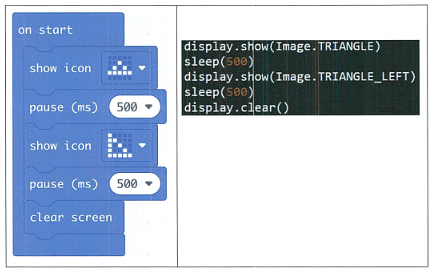
Look at the examples of MakeCode and MicroPython below. Discuss with a partner the
patterns you can see:
- Where are the similarities between the code?
- What words are used in MakeCode and MicroPython?
- Are there any words with similar meanings in the two examples?
Ans:
When comparing MakeCode and MicroPython, several patterns and similarities can be observed:
Similarities in Code:
- Both MakeCode and MicroPython use structured, logical steps to create sequences.
- They follow a similar flow, where actions are defined and executed in a sequence.
Words Used in MakeCode and MicroPython:
- MakeCode often uses block-based commands that represent code visually, such as "show icon", "pause", etc.
- MicroPython uses text-based commands, such as
display.show(),sleep(), etc.
Similar Words with Similar Meanings:
- MakeCode: "show icon" | MicroPython:
display.show() - MakeCode: "pause" | MicroPython:
sleep()
These commands, despite being represented differently, perform the same actions: displaying an image and pausing execution, respectively.
Q2.
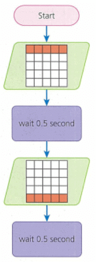
Look at this flowchart and discuss the questions below with a partner. ( start
- What patterns you can see?
- What sequence is being displayed?
- Use the patterns you see to extend the flowchart to display the same
images in the same sequence again.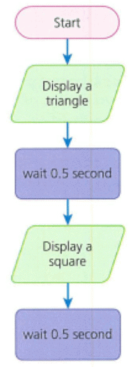
Ans:
Patterns:
- The flowchart likely follows a sequence of displaying images with pauses in between.
- Repetition and conditional steps can be identified to ensure continuous sequence display.
Sequence Displayed:
- Images are shown in a specific order, followed by pauses to make them visible.
- The flowchart's sequence can be extended by repeating the same pattern of actions.
Extending the Flowchart:
- To extend the flowchart, repeat the same set of display and wait steps in the same order.
- Ensure that each step is followed by the corresponding wait time (e.g., 0.5 seconds).
Q3.
Open the file LightSequenceChallenge.py provided by your teacher.
- Look at your flowcha rt from the previous act ivity and add the
MicroPython code to extend the light sequence.
- Connect the micro:bit to the device with the USB cable.
- Flash the program to the micro:bit to test it.
Ans:
- Open the file LightSequenceChallenge.py.
- Look at the flowchart from the previous activity to identify the pattern.
- Add the MicroPython code to extend the light sequence.
Connecting and Testing:
- Connect the micro to the device using the USB cable.
- Flash the program to the micro to test it.
Discussion Points for Activity
Discussion Questions:
Where are the similarities between the code?
- Both MakeCode and MicroPython involve displaying images and waiting for a period.
What words are used in MakeCode and MicroPython?
- MakeCode uses "show icon" and "pause", while MicroPython uses
display.show()andsleep().
- MakeCode uses "show icon" and "pause", while MicroPython uses
Are there any words with similar meanings in the two examples?
- Yes, "show icon" in MakeCode corresponds to
display.show()in MicroPython, and "pause" corresponds tosleep().
- Yes, "show icon" in MakeCode corresponds to
What patterns can you see in the flowchart?
- The flowchart likely has a repetitive pattern of displaying an image, waiting, and then transitioning to the next image.
What sequence is being displayed?
- The sequence includes showing a large square, small square, and then clearing the screen, with pauses in between each step.
How can you use the patterns to extend the flowchart?
- By repeating the sequence of displaying images and pauses to continue the pattern seamlessly.
MicroPython Code to Extend Light Sequence:
The code provided earlier extends the light sequence by repeating the same steps from the flowchart.
Patterns Between text-based programming languages
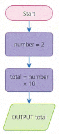
Q1. The flowchart below uses a variable to store an individual value, an integer. An integer is a whole number. Defining the data type
is important: if the program does not know it is an integer, it will not be able to perform a calculation.
- Look at the flowchart. What will be the output?
- What will be the output if the integer stored in the variable number is changed to 5?
Ans:
Let's analyze the given flowchart step by step to determine the output.
### Given Flowchart:
1. **Start**
2. **Set number = 2**
3. **Set total = number × 10**
4. **Output total**
### Steps to find the output:
1. The variable `number` is initialized to `2`.
2. The variable `total` is calculated as `number × 10`, which is `2 × 10`.
3. The value of `total` is then output.
**Output for the given flowchart:**
- \( number = 2 \)
- \( total = 2 \times 10 = 20 \)
- **Output = 20**
### If the integer stored in the variable `number` is changed to `5`:
1. The variable `number` is set to `5`.
2. The variable `total` is calculated as `number × 10`, which is `5 × 10`.
3. The value of `total` is then output.
**Output when `number` is changed to 5:**
- \( number = 5 \)
- \( total = 5 \times 10 = 50 \)
- **Output = 50**
So, the answers are:
1. The output for the given flowchart is **20**.
2. The output if the integer stored in the variable `number` is changed to 5 is **50**.
Q2. The flowchart above can be used to create a program in Python and MicroPython. Look at the Python and MicroPython programs in the table below and write down the patterns you see.

Ans:
Patterns and Differences:
Import Statements:
- Python: No import statement is needed for this simple program.
- MicroPython: The statement
from microbit import *is required to use the MicroPython-specific functions and hardware features, such asdisplay.scroll().
Variable Initialization and Arithmetic:
- Both Python and MicroPython initialize the variable
numberwith the value2and calculatetotalasnumber * 10.
- Both Python and MicroPython initialize the variable
Output Statements:
- Python: Uses the
print(total)function to output the result to the console. - MicroPython: Uses
display.scroll(total)to display the result on the micro's LED display.
- Python: Uses the
Summary of Patterns:
- Variable Assignment and Arithmetic: Both languages use similar syntax for variable assignment and arithmetic operations.
- Output Methods: Python uses
print()for console output, while MicroPython usesdisplay.scroll()for displaying output on the micro. - Imports: MicroPython requires specific imports to access hardware-related functions, while Python does not need such imports for basic operations.
Here is the HTML code that incorporates the analysis and patterns found in the Python and MicroPython programs:
Q3. Open the file CalculationProgram.py provided by your teacher.
- Connect the micro:bit to the device with the USB cable.
- Flash the program to the micro:bit to test it.
- Copy and apply the test plan below to predict the outcome and
then test the actual outcome.

Ans:
Open the CalculationProgram.py file:
- This file should contain the MicroPython code similar to what was mentioned earlier
from microbit import * number = 2 total = number * 10 display.scroll(total)
Connect the micro to your device:
- Use the USB cable to connect the micro to your computer.
Modify the program according to the test plan:
- Change the value of
numberin the program to match each test case.
- Change the value of
Flash the program to the micro:bit:
- Save the modified file and then transfer (flash) it to the micro.
Test the program:
- Observe the output on the micro's LED display.
Test Plan and Expected Outcomes
| Test Number | Data Entered | Expected Outcome | Pass/Fail |
|---|---|---|---|
| 1 | number = 5 | 50 | |
| 2 | number = 3 | 30 | |
| 3 | number = 6 | 60 | |
| 4 | number = 7 | 70 |
Instructions for Each Test:
Test 1:
- Modify the program to set
number = 5: - from microbit import * number = 5 total = number * 10 display.scroll(total)
- Flash the program to the micro
- The expected output on the LED display is
50.
- Modify the program to set
- Test 2:
- Modify the program to set
number = 3 - from microbit import * number = 3 total = number * 10 display.scroll(total)
- Flash the program to the micro
- The expected output on the LED display is
30.
- Modify the program to set
Test 3:
- Modify the program to set
number = 6 from microbit import * number = 6 total = number * 10 display.scroll(total)- Flash the program to the micro
- The expected output on the LED display is
60.
- Modify the program to set
Test 4:
- Modify the program to set
number = 7 from microbit import * number = 7 total = number * 10 display.scroll(total)- Flash the program to the micro.
- The expected output on the LED display is
70.
- Modify the program to set
Record the Results:
- After running each test, compare the actual output on the micro 's LED display with the expected outcome.
- Mark each test as "Pass" if the output matches the expected outcome, otherwise mark it as "Fail."
By following this process, you can systematically test and verify the correctness of your program using the provided test plan.
Q4. Using the same program, set the variable number to 5 and edit the arithmetic operator to copy and apply the following test plan:

Ans:
Q5. How did pattern recognition help you to complete these tasks? Explain to a partner.
Ans:
The Logic of AND/OR/NOT
Q1.
Look at this flowchart with a sub-routine.
(a) In pairs, follow the flowchart and explain how it works.
(b) What input will allow the sub-routine to run?
(c) How would a sad face be displayed?
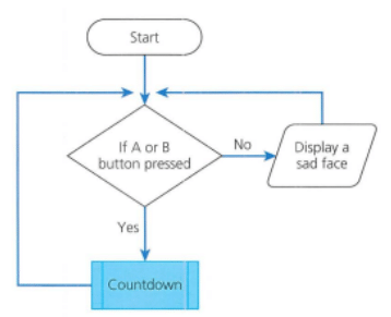
Q2. Use the software draw.io to create, view and edit flowcharts:
(a) Open a web browser and the URL https://app.diagrams.net
(b) Open the file SubroutineActivity.drawio provided by your teacher.
(c) Look at the selection used in this program. What will activate the sub-routine?
(d) How will a clear screen be displayed?
(e) The sub-routine should display a large heart followed by a small heart. However, there is an error and the sub-routine is not running at all. Can you find t he error and edit the flowchart? Double-click on the text within a shape to edit the wording.
Q3 . Open the file ANDprogram.py provided by you r teacher. The program displays the word 'Boolean' when the A AND B buttons are pressed. Create a flowchart using draw.io to represent this program.
Q4. Open the file ORprogram.py provided by your teacher. The program displays the word 'Boolean' when the A OR B button is pressed. Create a flowchart using draw.io to represent this program.
Q5. Open the file NOTprogram.py provided by your teacher. The program displays the word 'Boolean' when the B button is NOT pressed. Create a flowchart using draw.io to represent this program.
Q6. Discuss these questions with a partner:
- How could you use a sub-routine to help plan a light sequence for a visual alarm on the micro:bit?
- Think back to the Scenario on page 184 at the start of this unit. How could you use more than one input to activate your visual alarm?
Project Plans and test plans
Q1. Open the file PrototypeToTest.py provided by your teacher.This is the program for the flowchart on page 201.
- Connect the micro:bit to the device with the USB cable.
- Flash the program to the m icro:bit.
- Copy the test plan above (leave the pass/fail column blank).
- Apply the test plan to complete the tests on the software prototype and complete the pass/fail column .
Ans:
Q2. Discuss these questions in a small group:
- What did completing the test table show you?
- What is the purpose of a project plan?
- Think back to the Scenario on page 184 at the start of this unit. What tests could be included in a test plan for a visual alarm?
Ans:
Identifying errors and Debugging
Q1.
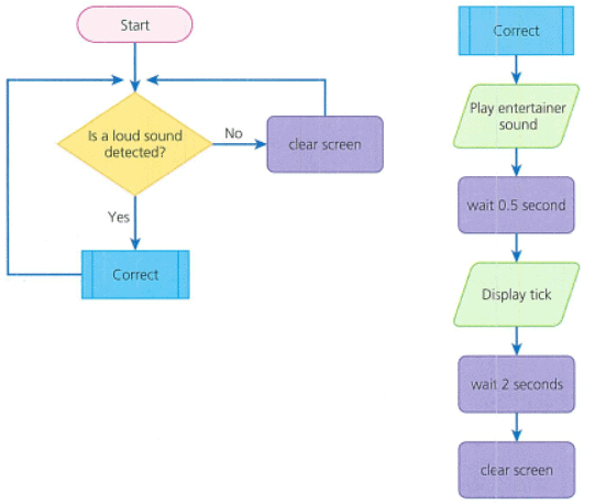
In a program, the sound sensor on the micro:bit is used to play a tune and display a tick if a loud sound is detected; else it will display a clear screen.
- Open the file DebugProgram.py given t o you by your teacher.
- Connect the micro:bit to the device with the USB cable.
- Flash the program to the micro:bit to test it.
- Use the checklist below to identify and debug any errors.
Debug possibilities checklist:
• Does the program start with from microbit im1Port *?
• Are brackets opened and closed when used?
• Is there a colon at the end of an if statement line?
• Are there capitals where there should be, such as the image to be displayed, e.g.
HAPPY?
• Does the string to be displayed have quotation m arks around it?
• Are code words spelled correctly?
- Flash the program to the m icro:bit again to test your debugging.
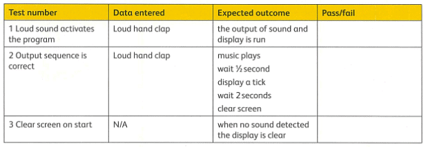
Q2. Once you have your program running, copy and apply the test plan below to check that the program works as expected.
Q3. Explain to a partner why debugging is important.
- What would happen if you did not test a program before releasing it?
- Give examples of errors that can be introduced when programming in MicroPython.
Sequences and Lights
Q1. Open the file LEDlightsl.py provided by your teacher.
- Edit the program to turn on the bottom-right LED.
- Connect the micro:bit to the device with the USB cable.
- Flash the program to the micro:bit to test it.
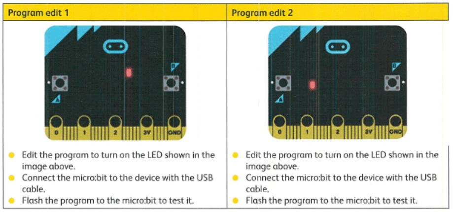
Q2. Using the file above, edit the file to carry out the following:
Q3. Open the file Pattern1Debug.py provided by your teacher. There is an error when you run this program .
- Connect the micro:bit to the device with the USB cable.
- Flash the program to the micro:bit to see the error.
- Edit the program to match the LEDs displayed for Pattern 1 below.
- Flash the program to the micro:bit to test it.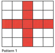
Q4. Open the file PatternStart.py provided by your teacher.
- Connect the micro:bit to the device with the USB cable.
- Flash the program to the micro:bit to see the error. Pattern 1
- Edit the program to match the LEDs displayed for Pattern 2 below.
- Flash the program to the micro:bit to test it.
- Continue to edit the program to display Patterns 3 and 4 below.

Ans:
Creating a moving sequence of lights
Q1. In the example above, the program displayed a moving image using two vertical lines.
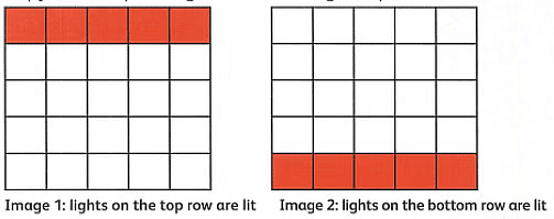
- Look at the flowchart below. It creates a similar pattern of images using two horizontal lines. Discuss with a partner what the program will do.
- Identify the pattern of where the 9s or Os need to be placed. Copy and complete a grid for each image output.
Ans:
Q2. Open the file HorizontalPattern.py provided by your teacher.
- Using your grids for help, edit the code to create a new moving
sequence of Image 1 followed by Image 2.
- Connect the micro:bit to the device with the USB cable.
- Flash the program to the micro:bit to test it.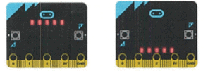
Ans:
Q3. Discuss with a partner:
- What are the advantages of using more than one image in a light sequence?
- Think back to the Scenario on page 184 at the start of this unit. Will using more than one image help to alert others in a visual alarm?
Ans:
Extending a Light Sequence
Q1. Create a program for these LED patterns on the micro:bit:

- First, draw the flowchart for the program .
- Using the flowchart, identify the pattern of where the 9s or 0s need to be placed.
Create a grid for each image.
Ans:
Q2. Open the file Sequence1Debug.py provided by your teacher.
- Connect the micro:bit to the device with the USB cable.
- Flash the program to the micro:bit to test it.
Ans:
Q3. There are some errors in the program, so the lights are not d isplaying as expected.
- Edit the code to correct the errors.
- Flash the program to the micro:bit to test that t hat it works correctly. It should show
the following output:
Ans:

Light Brightness
Q1. Open the file Flowchart plan.docx provided by your teacher.Complete the plan for the following sequence of images.
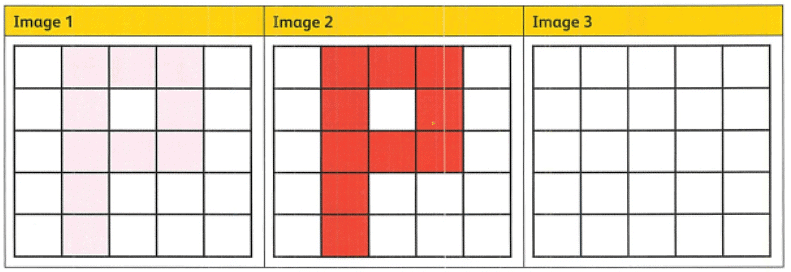
Ans:
Q2. Open the file SequenceStart.py provided by your teacher.
- Use your flowchart to edit the code to create a program that makes the letter P appear through increasing the brightness in t he image sequence.
- Flash the program to the micro:bit to test that it works correctly.
Ans:
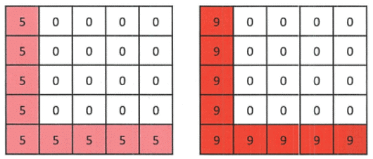
Q3. The images below are for a new light sequence.
- Predict what the out put will be on the micro:bit display.
-Open the file Sequence2Debug.py provided by your teacher.
- Connect the micro:bit to the device with the USB cable.
- Flash the program to the m icro:bit to test it.
- Identify the errors that have been made when creating the program code. Find and fix the errors.
- Flash the edited program to the micro:bit to test it.
Ans:
Q4. What is good about being able to control the briqhtness of the LED lights? Think back to the Scenario on page 184 at the start of the unit. How will using brightness help your visual alarm light sequence? Discuss your ideas with a partner.
Ans:
Go Further
Q1. At the start of this unit, you looked at the use of software prototypes; below is a prototype designed as part of a loading screen for a game on the micro:bit. The following sequence has been planned, but needs to be created as a program. Then the program needs to be tested and evaluated.

Open the file GoFurther.py provided by your teacher.
- Connect the micro:bit to the device with the USB cable.
- Flash the program to the micro:bit to test it.
- Edit the code to create the light sequence shown in the plan above.
- Flash the program to the micro:bit to test that it works correctly. Apply this test plan:
Ans:
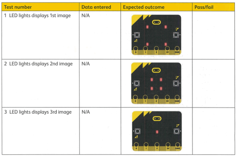
Q2. Can you edit the code to incl ude changing the brightness of the LED lights displayed?
Ans:
Q3. Evaluate the program. Discuss with a partner:
- What was good about the loading sequence?
- What could you do to improve the loading sequence?
Ans:
|
28 videos|17 docs|5 tests
|
FAQs on Textbook Solution: Sequencing and pattern recognition: Getting the message Across - IGCSE Cambridge Computing for Year 7 - Class 7
| 1. What are some strategies for improving sequencing and pattern recognition skills? |  |
| 2. How can sequencing and pattern recognition skills be applied in real-life situations? |  |
| 3. What are some common mistakes people make when trying to improve their sequencing and pattern recognition skills? |  |
| 4. How can teachers incorporate sequencing and pattern recognition activities in the classroom? |  |
| 5. How can technology be used to enhance sequencing and pattern recognition skills? |  |


