Theorem and Wheatstone Bridge Circuit | Modern Physics for IIT JAM PDF Download
Kirchhoff’s Voltage Law (K.V.L.) and Kirchhoff’s Current Law (K.C.L.)
Kirchhoff’s Voltage Law (K.V.L.)
Sum of the voltage in any closed loop must be zero considering same sign convention.
Sign Convention:
Lets consider that voltage is positive if we move from plus to minus then voltage is negative if we move from minus to plus. We can consider otherwise also.
Lets apply KVL in single loop network as shown in figure.
-V+IR+IRL=0 OR +V-IR-IRL=0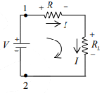

⇒ Req,12 =R+RL (Series equivalent of resistance)
Voltage Division Rule
Voltage drop across R is 
Voltage drop across RL is 
Kirchhoff’s Current Law (K.C.L.)
At any node sum of incoming current is equal to sum of outgoing current.
Thus
I1+I2+I3=I4+I5+I6
Current Division Rule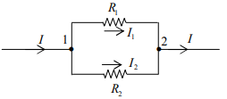
According to KCL at node 1 and 2: I=I1+I2 ....(i)
Since parallel voltages are equal: V12=V=VI1R1=I2R2 ...(ii)
Solve equation (i) and (ii) for I1 and I2 :


Two Loop Network
We can find current through each resistance using KVL and current division rule.
Lets apply KVL in two loop network as shown in figure.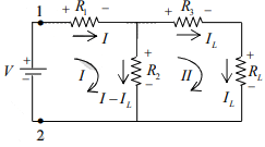

Solve equation (i) and (ii) for I and IL
Lets apply current division rule in two loop network as shown in figure.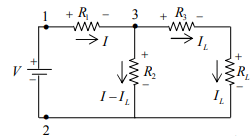

Lets apply current division rule at node 3:
Example: Find current across each element in the circuit shown in figure below.
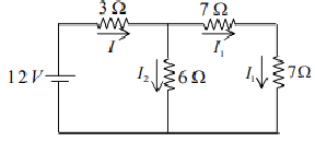
(a) Using current division rule
(b) Using KVL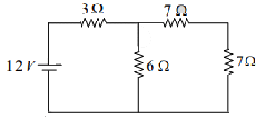
Solution: 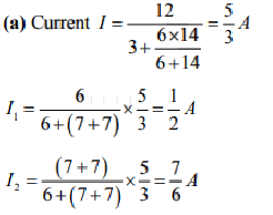
(b) Apply KVL in Loop I
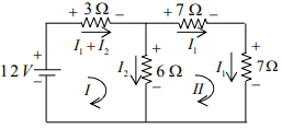
Solving above equations, we get 
Superposition Theorem
The superposition theorem states that in a network with two or more sources the current or voltage for any component is the algebraic sum of the effects produced by each source acting independently. In order to use one source at a time, all other sources are removed from the circuit or voltage source is removed by replacing it with a short circuit. A current source is removed by replacing it with an open circuit.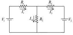


Direction of currents shown in figure are assumed directions, actual direction may be different.
Example: Using Superposition theorem find current across each element for the circuit shown in figure below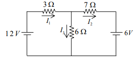
Solution:
Let us find current due to individual source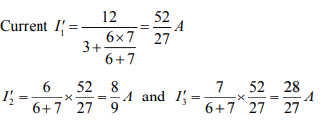
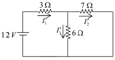
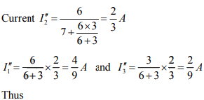
Let us find current due to second source.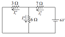

Thevenin theorem
Thevenin’s Theorem states that – any complicated network across its load terminals can be substituted by a voltage source with one resistance in series. This theorem helps in the study of the variation of current in a particular branch when the resistance of the branch is varied while the remaining network remains the same for example designing of electronics circuits
A more general statement of Thevenin’s Theorem is that any linear active network consisting of independent or dependent voltage and current source and the network elements can be replaced by an equivalent circuit having a voltage source in series with a resistance, that voltage source being the open circuited voltage across the open circuited load terminals and the resistance being the internal resistance of the source.
In other words, the current flowing through a resistor connected across any two terminals of a network by an equivalent circuit having a voltage source Eth in series with a resistor Rth. Where Eth is the open circuit voltage between the required two terminals called the Thevenin voltage and the Rth is the equivalent resistance of the network as seen from the two terminal with all other sources replaced by their internal resistances called Thevenin resistance.
Explanation of Thevenin’s Theorem
The Thevenin’s statement is explained with the help of a circuit shown below.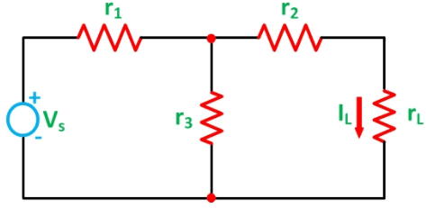
Let us consider a simple DC circuit as shown in the figure above, where we have to find the load current IL by the Thevenin’s theorem. In order to find the equivalent voltage source, rL is removed from the circuit as shown in the figure below and Voc or VTH is calculated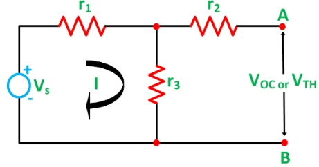

Now, to find the internal resistance of the network (Thevenin’s resistance or equivalent resistance) in series with the open circuit voltage VOC , also known as Thevenin’s voltage VTH, the voltage source is removed or we can say it is deactivated by a short circuit (as the source does not have any internal resistance) as shown in the figure below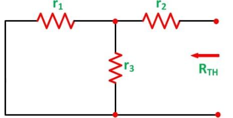

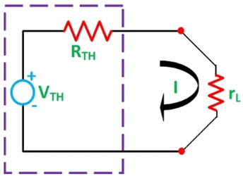
As per Thevenin’s Statement, the load current is determined by the circuit shown above and the equivalent Thevenin’s circuit is obtained.
The Load current IL is given as
Where,
VTH is the Thevenin’s equivalent voltage. It is an open circuit voltage across the terminal AB known as load terminal
RTH is the Thevenin’s equivalent resistance, as seen from the load terminals where all the sources are replaced by their internal impedance
rL is the load resistance
Steps for Solving Thevenin’s Theorem
Step 1 – First of all remove the load resistance rL of the given circuit.
Step 2 – Replace all the impedance source by their internal resistance.
Step 3 – If sources are ideal then short circuit the voltage source and open the current source.
Step 4 – Now find the equivalent resistance at the load terminals know as Thevenin’s Resistance (RTH).
Step 5 – Draw the Thevenin’s equivalent circuit by connecting the load resistance and after that determine the desired response.
This theorem is possibly the most extensively used networks theorem. It is applicable where it is desired to determine the current through or voltage across any one element in a network. The Thevenin’s Theorem is an easy way to solve the complicated network.
Norton’s Theorem
Norton’s Theorem states that – A linear active network consisting of independent or dependent voltage source and current sources and the various circuit elements can be substituted by an equivalent circuit consisting of a current source in parallel with a resistance.The current source being the short-circuited current across the load terminal and the resistance being the internal resistance of the source network.
The Norton’s theorems reduce the networks equivalent to the circuit having one current source, parallel resistance and load. Norton’s theorem is the converse of Thevenin’s Theorem. It consists of the equivalent current source instead of an equivalent voltage source as in Thevenin’s theorem. The determination of internal resistance of the source network is identical in both the theorems.
In the final stage that is in the equivalent circuit, the current is placed in parallel to the internal resistance in Norton’s Theorem whereas in Thevenin’s Theorem the equivalent voltage source is placed in series with the internal resistance.
Explanation of Norton’s Theorem
To understand Norton’s Theorem in detail, let us consider a circuit diagram given below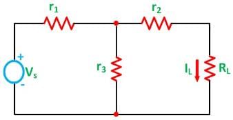
In order to find the current through the load resistance IL as shown in the circuit diagram above, the load resistance has to be short-circuited as shown in the diagram below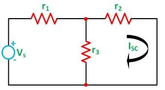
Now, the value of current I flowing in the circuit is found out by the equation
And the short-circuit current ISC is given by the equation shown below
Now the short circuit is removed, and the independent source is deactivated as shown in the circuit diagram below and the value of the internal resistance is calculated by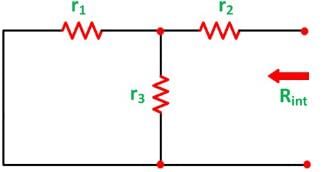

As per the Norton’s Theorem, the equivalent source circuit would contain a current source in parallel to the internal resistance, the current source being the short-circuited current across the shorted terminals of the load resistor. The Norton’s Equivalent circuit is represented as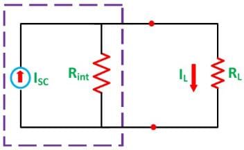
Finally the load current IL calculated by the equation shown below
Where,
- IL is the load current
- Isc is the short circuit current
- Rint is the internal resistance of the circuit
- RL is the load resistance of the circuit
Steps for Solving a Network Utilizing Norton’s Theorem
Step 1 – Remove the load resistance of the circuit.
Step 2 – Find the internal resistance Rint of the source network by deactivating the constant sources.
Step 3 – Now short the load terminals and find the short circuit current ISC flowing through the shorted load terminals using conventional network analysis methods.
Step 4 – Norton’s equivalent circuit is drawn by keeping the internal resistance Rint in parallel with the short circuit current ISC.
Step 5 – Reconnect the load resistance RL of the circuit across the load terminals and find the current through it known as load current IL.
Maximum Power Transfer Theorem
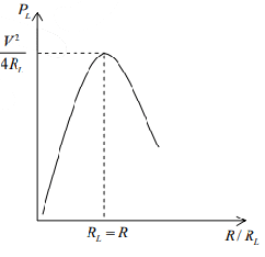
The maximum power is supplied by the voltage source and received by the load resistor if the value of the load resistor equals the value of the internal resistance of the voltage source. For maximum power transfer, then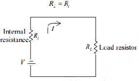
Power received at the load is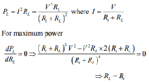
Wheatstone Bridge Circuit
The Wheatstone bridge can be used to measure an unknown resistance Rx . Switch S2 applies battery voltage to the four resistors in the bridge. To balance the bridge the value of R3 is varied. Balance is indicated by zero current in galvanometer G when switch S1 is closed.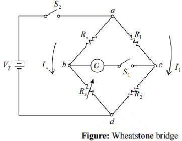
Rx, an unknown resistor
R1/R2, ratio arm
R3, standard resistor
When the bridge, balanced, points b and c must be at the same potential. Therefore
IxRx =I1R1 ...(1)
IxR3 =I1R2 ...(2)
the ratio arm of the bridge is R1/R2 . The bridge is balanced by varying R3 for zero current in the meter.
Note: When current flows through the meter path bc, the bridge circuit is unbalanced and must be analyzed by Kirchhoff’s laws or network theorems.
|
52 videos|44 docs|15 tests
|
FAQs on Theorem and Wheatstone Bridge Circuit - Modern Physics for IIT JAM
| 1. What is the Wheatstone Bridge circuit used for? |  |
| 2. How does the Wheatstone Bridge circuit work? |  |
| 3. What is the principle behind the Wheatstone Bridge circuit? |  |
| 4. What are the advantages of using a Wheatstone Bridge circuit? |  |
| 5. Can the Wheatstone Bridge circuit be used for measuring other physical quantities? |  |


