Theory of Seepage Flow | Civil Engineering SSC JE (Technical) - Civil Engineering (CE) PDF Download
THEORY OF SEEPAGE FLOW
The sub surface flow below a weir causes two definite instability problems as below.
1. Up lift forces due to the sub soil pressure that tends to lift up the barrage raft floor.
2. Upward rising seepage forces through the river bed just downstream of the solid apron causing sand particles to erupt upwards and tends to piping failure of the foundation.
Bligh’s creep theory: According to Bligh’s theory, the percolating water follows the outline of the base of the foundation of the hydraulic structure. The length of the path thus traversed by water is called the length of the creep. It is assumed that the loss of head is proportional to the length of the creep. If is the total head loss between the u/s and d/s and L is the length of creep, then HL/ L is called hydraulic gradient.Further, Bligh makes no distinction between horizontal and vertical creep.
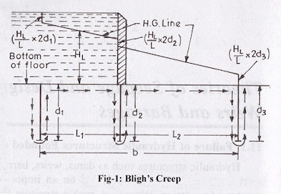
Safety against uplift pressure: Upward force = downward force
γwh'=γw ×G. t
h′ = G × t
Subtracting t on both sides, we get
(h′ – t) = (G×t – t) = t (G – 1)
Where,
h′ – t = h = Ordinate of the H.G line above the top of the floor
G – 1 = Submerged specific gravity of the floor material
Lane’s weighted creep theory:
It is same as Bligh’s theory but weightage of horizontal length is (1/3) and for vertical it is 1.
Therefore, L=LH/3+LV
Khosla’s theory:
The main principles of this theory are summarized below:
(a) The seepage water does not creep along the bottom contour of pucca flood as started by Bligh, but on the other hand, this water moves along a set of stream-lines. This steady seepage in a vertical plane for a homogeneous soil can be expressed by Laplacian equation:
Where, φ = Flow potential = Kh; K = the co-efficient of permeability of soil as defined by
Darcy’s law, and h is the residual head at any point within the soil.
The above equation represents two sets of curves intersecting each other orthogonally. The resultant flow diagram showing both of the curves is called a Flow Net.
Stream Lines:
The streamlines represent the paths along which the water flows through the sub-soil.
Every particle entering the soil at a given point upstream of the work, will trace out its own path and will represent a streamline. The first streamline follows the bottom contour of the works and is the same as Bligh’s path of creep. The remaining streamlines follows smooth curves transiting slowly from the outline of the foundation to a semi-ellipse, as shown below.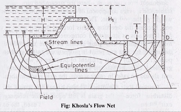
Equipotential Lines:-
(1) Treating the downstream bed as datum and assuming no water on the
downstream side, it can be easily started that every streamline possesses a head equal to h1 while entering the soil; and when it emerges at the down-stream end into the atmosphere, its head is zero. Thus, the head h1 is entirely lost during the passage of water along the streamlines.
Further, at every intermediate point in its path, there is certain residual head (h) still to be dissipated in the remaining length to be traversed to the downstream end. This fact is applicable to every streamline,and hence, there will be points on different streamlines having the same value of residual head h.
If such points are joined together, the curve obtained is called an equipotential line.
Every water particle on line AB is having a residual head h = h1, and on CD is having a residual head h = 0, and hence, AB and CD are equipotential lines.
Since an equipotential line represent the joining of points of equal residual head, hence if piezometers were installed on an equipotential line, the water will rise in all of them up to the same level as shown in figure below.
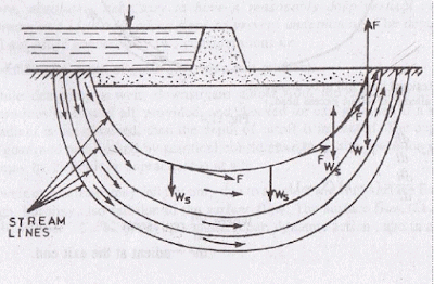
(2) The seepage water exerts a force at each point in the direction of flow and tangential to the streamlines as shown in figure above. This force (F) has an upward component from the point where the streamlines turns upward. For soil grains to remain stable, the upward component of this force should be counterbalanced by the submerged weight of the soil grain. This force has the maximum disturbing tendency at the exit end, because the direction of this force at the exit point is vertically upward, and hence full force acts as its upward component. For the soil grain to remain stable, the submerged weight of soil grain should be more than this upward disturbing force. The disturbing force at any point is proportional to the gradient of pressure of water at that point (i.e. dp/dt). This gradient of pressure of water at the exit end is called the exit gradient. In order that the soil particles at exit remain stable, the upward pressure at exit should be safe. In other words, the exit gradient should be safe.
Critical exit gradient:

This exit gradient is said to be critical, when the upward disturbing force on the grain is just equal to the submerged weight of the grain at the exit. When a factor of safety equal to 4 to 5 is used, the exit gradient can then be taken as safe. In other words, an exit gradient equal to ¼ to 1/5 of the critical exit gradient is ensured, so as to keep the structure safe against piping.
The submerged weight (Ws) of a unit volume of soil is given as:
= γw (1 – n) (Ss – 1)
where,
γw= unit weight of water.
Ss = Specific gravity of soil particles
n = Porosity of the soil material
Khosla's expression for exit gradient:
It has been determined that for a standard form consisting of a floor length b with a vertical cutoff of depth d, the exit gradient at its downstream end is given by
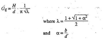
H = seepage head
b = horizontal distance between entry and exit points of impervious floor.
Khosla’s theory:
1. A composite profile is split into a no. of simple elementary standard forms for which the mathematical solution can easily be obtained.
2. Each elementary form is then treated independent of the other and the pressures at its key points of the entire structure.
3. Then the solutions of these elementary forms are superposed to obtain the pressure distribution at all the key points of the entire structure.
4. Further these pressures are to be corrected as the individual pressures have been obtained based on the assumption.
(a)the floor is of negligible thickness.
(b)there is only one pile line.
(c)the floor is horizontal.
5. Apply correction for these assumptions. (a) Thickness. (b) Interference (c) slope.
Uplift pressures at key points in elementary cases.
Case 1: Pile at downstream end
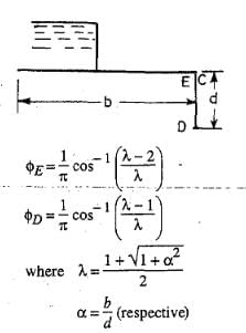
Case2: Pile at upsteram end 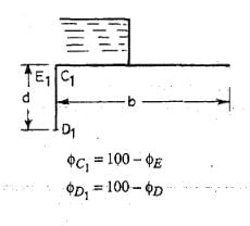
Case 3 : Intermediate Pile.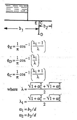
Case 4: Depressed floor
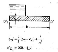
Correction for thickness of floor:
In the standard form profiles, the floor is assumed to have negligible thickness. Hence, the percentage pressures calculated by Khosla's equations or graphs shall pertain to the top levels of the floor. While the actual junction points E and C are at the bottom of the floor. Hence, the pressure at the actual points are calculated by assuming a straight line pressure variation. Since the corrected pressure at E1 should be less than the calculated pressure at E1', the correction to be applied for the point Er shall be -ve. Similarly, the pressure calculated at C1' is less than the corrected pressure at C1 and hence, the correction to be applied at point C1 is positive.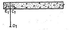
Correction for interference of piles:
The correction C to be-applied as percentage of head due to this effect, is given by
where
b' = The distance between two pile lines
D = The depth of the pile line, the influence of which has to be determined on the neighbouring pile of depth d. D is to be measured below the level at which inter-ference is desired.
d = The depth of the pile on which the effect is considered.
b = Total floor length.
Correction for sloping floor:
A correction is applied for a sloping floor and is taken as +ve for the down, and-ve for the up slopes following the direction of flow.
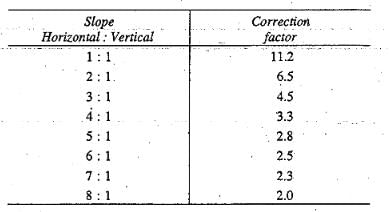
The correction factor given above is to be multiplied by the horizontal length of the slope and divided by the distance between the two pile lines between which the sloping floor is located. This correction is applicable only to the key points of the pile line fixed at the start or the end of the slope.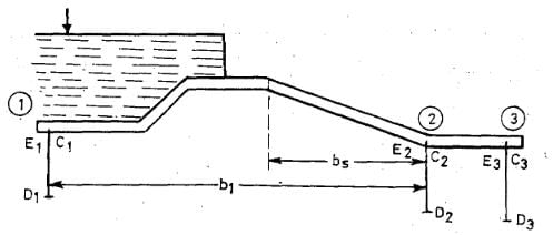
Thus, in Fig above, this correction is applicable only to point E2. Since the slope is down at point E2 in the direction of flow, hence, the correction shall be+ ve and will be equal to the correction factor for this slope (Table above) multiplied by bs/b1, where bs and b1 are shown in Fig above.
|
2 videos|122 docs|55 tests
|
FAQs on Theory of Seepage Flow - Civil Engineering SSC JE (Technical) - Civil Engineering (CE)
| 1. What is seepage flow? |  |
| 2. How does seepage flow occur? |  |
| 3. What are the factors that affect seepage flow? |  |
| 4. What are the applications of seepage flow theory? |  |
| 5. How is seepage flow controlled or prevented? |  |
|
2 videos|122 docs|55 tests
|

|
Explore Courses for Civil Engineering (CE) exam
|

|


