Electronics and Communication Engineering (ECE) Exam > Electronics and Communication Engineering (ECE) Notes > Electromagnetics > Transmission Lines - 1
Transmission Lines - 1 | Electromagnetics - Electronics and Communication Engineering (ECE) PDF Download
Introduction
- Transmission lines are used at frequencies from dc to about 50 or 60 GHz, but anything above 5 GHz only short runs are practical, because attenuation increases dramatically as frequency increases. There are three types of losses in conventional transmission lines: ohmic, dielectric, and radiation. An idealized transmission line consists of two parallel conductors of uniform cross-sectional area. The conductors possess a capacitance per unit length, C, and an inductance per unit length, L.
- In traditional low-frequency circuit analysis, the transmission line would not matter. As a result, the current that flows in the circuit would simply be:
l = V/Z → L = V/ZS + ZA - However, in the high frequency case, the length L of the transmission line can significantly affect the results. To determine the current that flows in the circuit, we would need to know what the input impedance is, Zin, viewed from the terminals of the transmission line:
- Examples of common transmission lines include the coaxial cable, the micro-strip line which commonly feeds patch/micro strip antennas, and the two wire line.
Voltage and Current Relationship
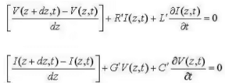
- Using ordinary circuit theory, the relationship between the voltage and current on the left and right side of the transmission line segment can be derived:


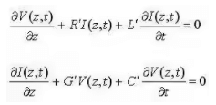
- Taking the limit as dz goes to zero, we end up with a set of differential equations that relates the voltage and current on an infinitesimal section of transmission line:

- Using ordinary differential equations theory, the solutions for the above differential equations are given by:
V(z,t) = V+e(jat - yz) + V-e(jat + yz)
I(z,t) = I+e(jat - yz) + l-e(jat + yz)
The solution is the sum of a forward traveling wave (in the +z direction) and a backward traveling wave (in the -z direction). In the above, V+ is the amplitude of the forward traveling voltage wave,V- is the amplitude of the backward traveling voltage wave, I+ is the amplitude of the forward traveling current wave, and I- is the amplitude of the backward traveling current wave.
Characteristic impedance (Z0)
- It is defined as the ratio of the magnitude of the forward traveling voltage wave to the magnitude of the forward traveling current wave:
Z0 = V+/l+ = - V-/l- - In terms of the transmission line per-length parameters, the characteristic impedance is given by:

Lossless Transmission line and Distortionless Transmission line
- If R'=G'=0, then the conductors of the transmission line are perfectly conducting (so R'=0) and the dielectric medium that separates the conductors has zero conductivity (so that G'=0). In this case, the line is referred to as a Lossless Line. The characteristic impedance becomes:

- Another type of line of interest is the distortionless line, This type of line may contain loss (so that the voltage dies off somewhat as it propagates down the line), but the magnitude of the attenuation is frequency-independent, and the phase constant varies linearly with frequency. This is desirable; similar to filter theory, this would be considered "linear phase" - that is, signals that come out of the transmission line might be attenuated, but have the same shape. The criteria for this is:
R'/L' = G'/C' (criteria for distortionless line) - The characteristic impedance becomes:
 (distortionless line)
Propagation constant
- The propagation constant shows up in the solution for the spatial variation of the voltage and current waves along the line (see above). The real part is given by α; this represents the rate of decay of the wave as it travels down the transmission line. The larger is α, the more "lossy" the line is, and the faster the wave decays. If α=0, then the line is lossless, and the voltage and current waves do not die (shrink) as they travel down the line.
- The imaginary part of the propagation constant is given by β. This represents the rate at which the waves oscillate as a function of position on the line. In contrast, frequency represents the rate of change of oscillation as function of time. For a lossless line, β can be determined from the speed of propagation along the line (u). In general, β can be determined from:

- The Propagation Constant: y = α + jβ
- Therefore final relation would be:
Voltage Reflection Coefficient
We are now aware of the characteristic impedance of a transmission line, and that the tx line gives rise to forward and backward travelling voltage and current waves. We will use this information to determine the voltage reflection coefficient, which relates the amplitude of the forward travelling wave to the amplitude of the backward travelling wave.
- To begin, consider the transmission line with characteristic impedance Z0 attached to a load with impedance ZL:

- ZL = RL + jXL
- At the terminals where the transmission line is connected to the load, the overall voltage must be given by:
V/I = ZL - Putting this relation in voltage and current relationship expressions and we get:

- The ratio of the reflected voltage amplitude to that of the forward voltage amplitude is the voltage reflection coefficient. This can be solved for via the above equation:

Standing Waves
- We'll now look at standing waves on the transmission line. Assuming the propagation constant is purely imaginary (lossless line), We can re-write the voltage and current waves as:
V(z) = V+(e-jβz + Γejβz)
I(z) = V+/Z0(e-jβz + Γejβz) - After plotting graphs on above equations, we came on to a conclusion that the ratio of Vmax to Vmin becomes larger as the reflection coefficient increases. That is, if the ratio of Vmax to Vmin is one, then there are no standing waves, and the impedance of the line is perfectly matched to the load. If the ratio of Vmax to Vmin is infinite, then the magnitude of the reflection coefficient is 1, so that all power is reflected. Hence, this ratio, known as the Voltage Standing Wave Ratio (VSWR) or standing wave ratio is a measure of how well matched a transmission line is to a load. It is defined as:

The document Transmission Lines - 1 | Electromagnetics - Electronics and Communication Engineering (ECE) is a part of the Electronics and Communication Engineering (ECE) Course Electromagnetics.
All you need of Electronics and Communication Engineering (ECE) at this link: Electronics and Communication Engineering (ECE)
|
11 videos|94 docs|89 tests
|
FAQs on Transmission Lines - 1 - Electromagnetics - Electronics and Communication Engineering (ECE)
| 1. What is the relationship between voltage and current in a transmission line? |  |
Ans. In a transmission line, voltage and current are directly related. This relationship is governed by Ohm's Law, which states that the voltage across a conductor is equal to the current flowing through it multiplied by its resistance. Therefore, if the resistance of the transmission line remains constant, an increase in current will result in a proportional increase in voltage and vice versa.
| 2. What is characteristic impedance (Z0) in a transmission line? |  |
Ans. Characteristic impedance (Z0) is a fundamental property of a transmission line that represents the ratio of voltage to current in a wave propagating along the line. It is the impedance at which the line appears purely resistive and is independent of its length. The characteristic impedance is determined by the line's physical parameters, such as its capacitance, inductance, and conductance.
| 3. What is the difference between a lossless transmission line and a distortionless transmission line? |  |
Ans. A lossless transmission line is one in which there is no power dissipation along the line. This means that the line has no resistance or conductance, and all of the power supplied to it is fully transmitted with no losses. On the other hand, a distortionless transmission line is one in which the wave shape of the signal remains unchanged as it propagates along the line. This means that there is no distortion or distortion-free transmission of the signal, but there may still be some power loss due to resistance.
| 4. What is the propagation constant in a transmission line? |  |
Ans. The propagation constant, denoted by γ (gamma), is a complex number that represents the rate at which a wave propagates along a transmission line. It includes both the phase constant and the attenuation constant. The phase constant determines the phase shift of the wave as it travels along the line, while the attenuation constant represents the rate at which the wave's amplitude decreases due to losses in the line.
| 5. What is the voltage reflection coefficient in a transmission line? |  |
Ans. The voltage reflection coefficient, denoted by Γ (gamma), is a complex number that quantifies the reflection of voltage waves at the interface between two transmission lines or at the load. It represents the ratio of the amplitude of the reflected voltage wave to the amplitude of the incident voltage wave. A value of 0 for the voltage reflection coefficient indicates no reflection (perfect matching), while a value of 1 indicates complete reflection.
Related Searches


