Transmission Lines - 2 | Electromagnetics - Electronics and Communication Engineering (ECE) PDF Download
Behaviour of Transmission line due to variation in Load Impedance (ZL)
- Short-Circuited Lines: Consider a transmission line of length L, but suppose the end of the line is short-circuited together (so that ZA=0). We can determine the input impedance (or input admittance = 1/Z) for a short circuited line.
Zin = jZ0 tan (βL)
- Open-Circuited Transmission Lines: if a transmission line is terminated in an open circuit (so that ZA is infinite), then the impedance of a line of length L is given by:
Zin = JZ0 cot(βL)
Yin = j tan(βL)/Z0 - If you measure the open- and short-circuited impedances of a transmission line for any fixed length L, the characteristic impedance (Z0) can be determined:
Zinshort = jZ0 tan(βL)
Zinopen = - jZ0 cot(βL)
- For Matched Line: Zin = Zo
Smith chart
Smith chart is graphical technique used for calculating reflection coefficient and standing wave ratio for normalized load impedance.
Characteristics of constant R-circles and X-circles
- constant resistance circles have centre at [r/(1+r),0] and radius r/(1+r).
- constant reactance circles have centre at (1, 1/x) and radius 1/x.
- λ/2 distance is equal to a full revolution on the chart.
- all the constant resistance and reactance circles pass through (1,0).
- clockwise movement on chart implies movement towards generator
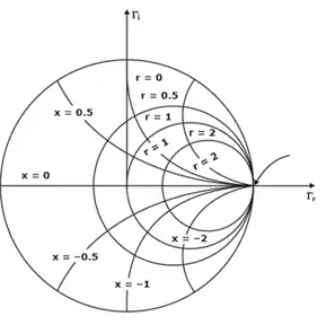 Various impedances on Smith Chart
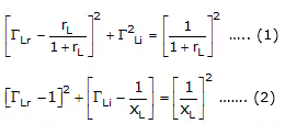
Above Equation (1) represents a family of constant resistance circles whose center and radius are given by
center = (rL/1+rL,0)
radius = 1/1 + rL
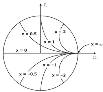
Equations (2) represent a family of constant reactance circles whose center and radius are given by
center (1, 1xL)
radius 1/xL
NOTE: As we move from point to point along the transmission line plotting the complex reflection coefficient which is obtained by rotating around the constant VSWR circle, we are also plotting the corresponding impedance.
Once a normalized impedance is located on the Smith chart for a particular point on t he transmission line, the corresponding normalized admittance is found by rotating 180° from the impedance point on the constant VSWR circle.
The maxima and minima location for voltages and currents along the transmission line can be located using the Smith chart given that these values correspond to specific impedance characteristics.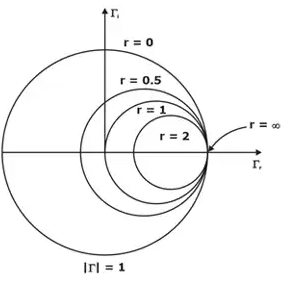 Impedance and corresponding Admittance on Smith Chart
Voltage maximum, Current minimum : Impedance maximum
Voltage minimum, Current maximum : Impedance minimum
 Maximas and Minimas on Smith Chart
Applications of Smith Chart
Smith chart can be used for the following purposes:
- To find the normalised admittance from normalised impedance and vice-versa.
- To find the parameters of mismatched transmission lines.
- To find the standing wave ratio for a given load impedance.
- To find the reflection coefficient.
- To find the input impedance of a transmission line.
- To locate a voltage maximum on a transmission line.
- To design stubs for impedance matching.
Impedance matching Techniques
Impedance Matching is the process of removing mismatch loss. i.e. the reflection coefficient should be minimized, to reduce the power reflected from the load (the antenna), and maximize the power delivered to the antenna. This is one of the fundamental tasks in getting an antenna to radiate, and hence is one of the more important topics in antenna theory. It is accomplished by placing intermediate devices:
- Quarter wave Transformer: This technique is generally used for matching a resistive load to a transmission line (a), for matching two resistive loads(b),or for matching two transmission lines with unequal characteristic impedances (c)
- Most load impedances are typically large and line impedances are small so we have to use additional elements for matching
Series –λ/4– Quarter wave transformer - Let us assume that the characteristic impedance of the transformer section is Zox. For λ/4 length, the transformer inverts the normalized impedance. Therefore the impedance seen at A towards right in Figure (a) would be
The Z0 line has a termination = Zin of the λ/4 line of ZL load = z'o2/ZL
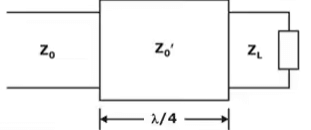 With the use of the quarter wave transformer the line is completely matched but the load is not completely matched but the miss match is reduced as compare without the λ/4 transformer.
Disadvantages
- If operational frequency changes the λ/4 line behavior changes and hence this technique is preferred for marrow range of frequencies.
- The technique is preferred only for resistive loads and lossless lines only so that Z’0 is real and hence lossless
Shunt–Stub Matching
A stub is a short circuit line of lt length placed at ls distance from the load such that the function impedance is Z0 and the line is matched, from that point towards the source.
Design of a stub
Identity a position on the line from the load where Z(x) = Z0 ± jx then x value is is position of stub
At this stub position and equal and opposite reactance is placed in shunt that cancels existing reactance so that the junction impedance.
This junction impedance is Z0 as the cancelling reactance is designed form a short–circuit line of ‘lt’ length
For the miss–matched region to be small ‘ls’ should be as close to the load as possible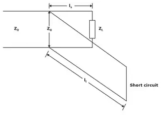 Matching with a single stub tuner
|
11 videos|94 docs|89 tests
|
FAQs on Transmission Lines - 2 - Electromagnetics - Electronics and Communication Engineering (ECE)
| 1. What is a transmission line? |  |
| 2. What are the types of transmission lines? |  |
| 3. What is characteristic impedance in transmission lines? |  |
| 4. How are transmission lines used in telecommunications? |  |
| 5. What are some common challenges in transmission line design and maintenance? |  |


