Types: Waves | Physics for Airmen Group X - Airforce X Y / Indian Navy SSR PDF Download
1. Sound Waves
Sound is type of longitudinal wave. In general majority of longitudinal waves are termed as sound waves. Sound is produced by a vibrating source, like when a gong of a bell is struck with a hammer, sound is produced. The vibrations produced by gong are propagated through air, Through air these vibrations reach to the ear and ear drum is set into vibrations and these vibrations are communicated to human brain. By touching the gong of bell by hand, we can feel the vibrations.
2. PROPAGATION OF SOUND WAVES
Sound is a mechanical three dimensional and longitudinal wave that is created by a vibrating source such a guitar string, the human vocal cords, the prongs of a tuning fork or the diaphragm of a loudspeaker. Being a mechanical waves, sound needs a medium having properties of inertia and elasticity for its propagation. Sound waves propagate in any medium through a series of periodic compressions and rarefactions of pressure, which is produced by the vibrating source.
Consider a tuning fork producing sound waves.

When Prong B moves outward towards right it compresses the air in front of it, causing the pressure to rise slightly. The region of increased pressure is called a compression pulse and it travels away from the prong with the speed of sound
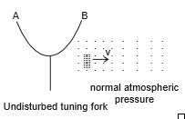
After producing the compression pulse, the prong B reverses its motion and moves inward. This drags away some air from the region in front of it, causing the pressure to dip slightly below the normal pressure. This region of decreased pressure is called rarefaction pulse. Following immediately behind the compression pulse, the rarefaction pulse also travels away from the prong with the speed of sound.

A longitudinal wave in a fluid is described either in terms of the longitudinal displacements suffered by the particles of the medium.

Consider a wave going in the x-direction in a fluid. Suppose that at a time t, the particle at the undisturbed position x suffers a displacement y in the x-direction.
y = A sin w  ...(i)
Position of any particle from origin at any time = x + y
x = Distance of the mean position of the particle from the origin.
y = Displacement of the particle from its mean position.
General Equation :

If we fix x = x0 then we are dealing with the particle whose mean position at distance x0 from origin & this particle is performing SHM of amp. A with time period T phase difference = - kx + f
3. Compression Waves
When a longitudinal wave propagated in a gaseous medium, it produces compression and rarefaction in the medium periodically. The region where compression occurs, the pressure is more than the normal pressure of the medium. Thus we can also describe longitudinal waves in a gaseous medium as pressure waves and these are also termed as compression waves in which the pressure at different point of medium also varies periodically with their displacements. Let us discuss the propagation of excess pressure in a medium in longitudinal wave analytically.

Consider a longitudinal wave propagating in positive x-direction as shown in figure. Figure shows a segment AB of the medium of width dx. In this medium let a longitudinal wave is propagating whose equation is given as

Where y is the displacement of medium particle situated at a distance x from the origin, along the direction of propagation of wave. In figure shown AB is the medium segment whose a medium particle is at position x = x and B is at x = x dx at an instant. If after some time t medium particle at A reaches to a point A' which is displaced by y and the medium particle at b reaches to point B¢ which is at a displacement y dy from B. Here dy is given by equation (3.116) as

Here due to displacement of section AB to A¢B¢ the change in volume of it's section is given as

The volume of section AB is V = S dx
Thus volume strain in section AB is

If B is the bulk modulus of the medium, then the excess pressure in the section AB can be given as
ΔP = - ...(2)
DP = BAk cos (wt - kx)
or DP = DP0cos(wt - kx) ...(3)
Here DP0 is the pressure amplitude at a medium particle at position x from origin and DP is the excess pressure at that point. Equation shown that excess varies periodically at every point of the medium with pressure amplitude DP0, which is given as
DP0 = BAk =  AB ...(4)
Equation shown is also termed as the equation of pressure wave in gaseous medium. We can also see that the pressure wave differs in phase is p/2 from the displacement wave and pressure maxima occurs where the displacement is zero and displacement maxima occur where the pressure is at its normal level. Remembers that pressure maxima implies that the pressure at a point is pressure amplitude times more or less then the normal pressure level of the medium.
Ex.1 A sound wave of wavelength 40 cm travels in air. If the difference between the maximum and minimum pressures at a given point is 2.0 × 10⁻³ N/m2, find the amplitude of vibration of the particles of the medium. The bulk modulus of air is 1.4 × 10⁵ N/m2
Sol. The pressure amplitude is

The displacement amplitudes s0 is given by
Density Wave
In this section we will find the relation between pressure wave and density wave.
According to definition of bulk modulus (B),

Further, 
or  or
or 
or 
Substituting in Eq. (i)f we get 
Or this can be written as,
So, this relation relates the pressure equation with the density equation. For example, if
Thus, density equation is in phase with the pressure equation and this is 90° out of phase with the displacement equation.
3.1 Velocity and Acceleration of particle :
General equation of wave is given by

Here  slope of (y, x) curve Now again differentiate eq. - 3
from eq. {2) & (4)
4. Velocity of Sound/Longitudinal Waves in Solids
Consider a section AB of medium as shown in figure(a) of cross-sectional area S. Let A and B be two cross section as shown. Let in this medium sound propagation is from left to right. If wave source is at origin O and when it oscillates, the oscillations at that point propagate along the rod.


Here we say an elastic wave has propagated along the rod with a velocity determined by the physical properties of the medium. Due to oscillations say a force F is developed at every point of medium which produces a stress in rod and is the cause of strain or propagation of disturbance along the rod. This stress at any cross-sectional area can be given as
Stress S1 =  ...(1)
If we consider the section AB of medium at a general instant of time t. The end A is at a distance x from O and B is at a distance x dx from O. Let in time dt due to oscillations, medium particles at a are displaced along the length of medium by y and those at B by y dy. The resulting position of section and A¢ and B¢ shown in figure (b), Here we can say that the section AB is deformed (elongated) by a length dy. Thus strain produced in it is
Strain in section AB  ...(2)
If Young's modulus of the material of medium is Y, we have
Young's Modulus Y =  =
= 
From equation (1) and (2), we have 
or  ...(3)
If net force acting on section AB is dF then it is given as
dF = dma ...(4)
Where dm is the mass of section AB and a be its acceleration, which can be given as for a medium of density r.
dm = rSdx and a = 
From equation (4), we have dF = (rSdx) 
or  ...(5)
From equation (3) on differentiating w.r. to x, we can write
 ...(6)
From equation (5) and (6) we get
 ....(7)
Equation (7) is the differential form of wave equation, comparing it with previous equation we get the wave velocity in the medium can be given as

Similar to the case of a solid in fluid, instead of Young's Modulus we use Bulk modulus of the medium hence the velocity of longitudinal waves in a fluid medium is given as

Where B is the Bulk modulus of medium.
For a gaseous medium bulk modulus is defined as
 or
or 
4.1 Newton's Formula for velocity of Sound in Gases
Newton assumed that during sound propagation temperature of medium remains constant hence the stated that propagation of sound in a gaseous medium is an isothermal phenomenon, thus Boyle's law can be applied in the process. So for a section of medium we use
PV = constant
Differentiating we get
PdV + V dP = 0
or 
or bulk modulus of medium can be given as
B = P (Pressure of medium)
Newton found that during isothermal propagation of sound in a gaseous medium, bulk modulus of medium is equal to the pressure of the medium, hence sound velocity in a gaseous medium can be given as
 ...(1)
From gas law we have  ...(2)
From (1) & (2) we have  ...(3)
From the expression in equation (1) if we find the sound velocity in air at normal temperature and atomspheric pressure we have
Normal atmospheric pressure is P = 1.01 × 10⁵ Pa
Density of air at NTP is r = 1.293 kg/m3
Now from equation (1) v =  ⇒
⇒  = 279.45 m/s
But the experimental value of velocity of sound determined from various experiments gives the velocity of sound at NTP, 332 m/s. Therefore there is a difference of about 52 m/s between the theoretical and experimental values. This large difference can not be attributed to the experimental errors. Newton was unable to explain error in his formula. This correction was explained by a French Scientist Laplace.
4.2 Laplace Correction
Laplace explained that when sound waves propagated in a gaseous medium. There is compression and rarefaction in the particles of medium. Where there is compression, particles come near to each other and are heated up, where there is rarefaction, medium expends and there is fall of temperature. Therefore, the temperature of medium at every point does not remain constant so the process of sound propagation is not isothermal. The total quantity of heat of the system as a whole remains constant. medium does not gain or loose any heat to the surrounding. Thus in a gaseous medium sound propagation is an adiabatic process. For adiabatic process the relation in pressure and volume of a section of medium can be given as
PVg = constant ...(1)
Here g =  , ratio of specific heats of the medium.
Differentiating equation (1) we get,
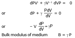
Thus Laplace found that during adiabatic propagation of sound, the Bulk modulus of gaseous medium is equal to the product of ratio of specific heats and the pressure of medium. Thus velocity of sound propagation can be given as

From gas law 
From above equation we find sound velocity in air at NTP, we have
Normal atmospheric pressure P = 1.01 × 10⁵ Pa
Density of air at NTP P = 1.293 kg/m3
Ratio of specific heat of air 
⇒  =
=  = 333.04 m/s
This value is in agreement with experimental value.
Now at any temperature t°C velocity of sound vt =  =
= 
vt = v0
4.3 Effect of Temperature on Velocity of Sound
We have velocity of sound propagation in a gaseous medium as

For a given gaseous medium g, R and M remains constant, thus velocity of sound is directly proportional to square root of absolute temperature of the medium. Thus

If at two different temperatures T1 and T2, sound velocities in medium are v1 and v2 then from above equation we have

4.4 Effect of Pressure on Velocity of Sound
We know form gas law

If temperature of a medium remains constant then on changing pressure, density of medium proportionally changes so that the ratio  remains constant.
Hence if in a medium, T = constant
Then,  = constant
Thus velocity of sound, v =  = constant
Therefore, the velocity of sound in air or in a gas is independent of change in pressure.
4.5 Effect of Humidity on Velocity of Sound
The density of water vapour at NTP is 0.8 kg/m3 whereas the density of dry air at NTP is 1.293 kg/3. Therefore water vapour has a density less than the density of dry air. As atmospheric pressure remains approximately same, the velocity of sound is more in moist air then the velocity of sound in dry air.
vmoist air > vdry air (from the previous equation)
4.6 Effect of Wind on Velocity of Sound
If wind is blowing in the direction of propagation of sound, it will increase the velocity of sound, On the other hand if wave propagation is opposite to the direction of propagation of wind, wave velocity is decreased. If wind blows at speed vw then sound velocity in the medium can be given as

Where  is the velocity of sound in still air.
5. Appearance of sound to human ear
The appearance of sound to a human ear is characterized by three parameters (a) pitch (b) loudness and (c) quality.
(a) Pitch and Frequency
Pitch of a sound is that sensation by which we differentiate a buffalo voice, a male voice and a female voice. We say that a buffalo voice is of low pitch, a male voice has higher pitch and a female voice has still higher pitch. This sensation primarily depends on the dominant frequency present in the sound. Higher the frequency, higher will be the pitch and vice versa.
(b) Loudness and Intensity
The loudness that we sense is related to the intensity of sound though it is not directly proportional to it. Our perception of loudness is better correlated with the sound level measured in decibels (abbreviated as dB) and defined as follows.

where I is the intensity of the sound and I0 is a constant reference intensity 10-12 W/m2 The reference intensity represents roughly the minimum intensity that is just audible at intermediate frequencies. For
I = I0 , the sound level b = 0.
(c) Quality and Waveform
A sound generated by a source may contain a number of frequency components in it. Different frequency components have different amplitudes and superposition of them results in the actual waveform. The appearance of sound depends on this waveform apart from the dominant frequency and intensity. Figure shows waveforms for a tuning fork, a clarinet and a cornet playing the same note (fundamental frequency = 440 Hz) with equal loudness.


We differentiate between the sound from a tabla and that from a mridang by saying that they have different quality.
(d) Energy in sound Waves


6. Analytical Treatment of Interference of Waves

Interference implies super position of waves. Whenever two or more than two waves superimpose each other at some position then the resultant displacement of the particle is given by the vector sum of the individual displacements.
Let the two waves coming from sources S1 & S2 be

Due to superposition


 (where Δx = path difference &. Δφ = phase difference)

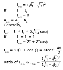
When the two displacements are in phase, then the resultant amplitude will be sum of the two amplitude & Inet will be maximum, this is known of constructive interference.
For Inet to be maximum

For constructive interference

When superposing waves are in opposite phase, the resultant amplitude is the difference of two amplitudes & Inet is minimum; this is known as destructive interference.

For destructive interference
7. Longitudinal standing waves
Two longitudinal waves of same frequency and amplitude travelling in opposite directions interfere to produce a standing wave.
If the two interfering waves are given by

then the equation of the resultant standing wave would be given by

This is equation of SHM in which the amplitude p0' depends on position as

Points where pressure remains permanently at its average value, i.e., pressure amplitude is zero is called a pressure node, and the condition for a pressure node would be given by

Similarly points where pressure amplitude is maximum is called a pressure anti-node and condition for a pressure anti-node would be given by

Note :
- Note that a pressure node in a standing wave would correspond to a displacement antinode; and a pressure anti-node would correspond to a displacement node.
- (when we label eqn. (1) as SHM, what we mean that excess pressure at any point varies simple harmonically. if the sound waves were represented in terms of displacement waves, then the equation of standing wave corresponding to (1) would be

This can be easily observed to be an equation of SHM. It represents the medium particles moving simple harmonically about their mean position at x.
8. Reflection of sound Waves
Reflection of sound waves from a rigid boundary (e.g. closed end of an organ pipe) as analogous to reflection of a string wave from rigid boundary; reflection accompanied by an inversion i.e. an abrupt phase change of p. This is consistent with the requirement of displacement amplitude of remains zero at the rigid end, since a medium particle at the rigid end can not vibrate. As the excess pressure and displacement corresponding to the same sound wave vary by p/2 in term of phase, a displacement minima at the rigid end will be a point of pressure maxima. This implies that the reflected pressure waves from the rigid boundary will have same phase as the incident wave, i.e., a compression pulse is reflected as a compression pulse and a rarefaction pulse is reflected as a rarefaction pulse
On the other hand, reflection of sound wave from a low pressure region (like open end of an organ pipe) is analogies to reflection of string wave from a free end. This point corresponds to a displacement maxima, so that the incident & reflected displacement wave at this point must be in phase. This would imply that this point would be a minima for pressure wave (i.e. pressure at this point remains at its average value), and hence the reflected pressure wave would be out of phase by p with respect to the incident wave. i.e. a compression pulse is reflected as a rarefaction pulse and vice-versa.
9. Waves in a Vibrating air Column
Hollow pipes have long used for making musical sounds. A hollow pipe we call organ pipe. To understand how these work, first we examine the behaviour of air in a hollow pipe that is open at both ends. If we blow air across one end, the disturbance due to the moving air at that end propagates along the pipe to the far end. When it reaches far end, a part of the wave is reflected, similar in the case when a wave is reflected along a string whose end point is free to move. Since the air particles are free to move at the open end, the end point is an anti-node. if one end of the pipe is closed off, the the air is not free to move any further in that direction and closed end becomes a node. now the resonant behaviour of pipe is completely changed. Similar in the case of string, here also all harmonic frequencies are possible and resonance may take place it the frequency of external source matches with any of the one harmonic frequency of pipe. Let us discuss in detail.
9.1 Vibration of Air in a Closed Organ Pipe
When a tuning fork is placed near the open end of a pipe. The air in the pipe oscillates with the same frequency as that of tuning fork. Here the open end should be an anti-node and closed and should be a node for perfect reflection of waves from either end or for formation of stationary waves. Since one end is a node and other is an anti-node, the lowest frequency (largest wavelength) vibration has no other nodes or anti-nodes between ends as shown in figure(a). This is the fundamental (minimum) frequency at which stationary waves can be formed in a closed organ pipe. Thus if the wavelength is l then we can see from figure (a), which shows the displacement wave of longitudinal waves in the closed organ pipe.
l =  ...(1)
or l = 4 l


Thus fundamental frequency of oscillations of closed organ pipe of length l be given as
n1 =  =
=  ...(2)
Similarly first overtone of closed pipe vibrations is shown in figure (b) here wavelength l¢ and pipe length l are related as
 ...(3)
or 
Thus frequency of first overtone oscillations of a closed organ pipe of length l can be given as
n2 =  =
=  ...(4)
= 3n1
This is three times the fundamental frequency thus after fundamental only third harmonic frequency exist for a closed organ pipe at which resonance can take place or stationary waves can be formed in it.
Similarly next overtone, second overtone is shown in figure(c). Here the wavelength l¢¢ and pipe length l are related as

or 
Thus the frequency of second overtone oscillation of a closed organ pipe of length l can be given as
n3 =  =
= 
This is fifth harmonic frequency of fundamental oscillations.
In general f = 
Here frequency of oscillation is called (2n - 1)th harmonic and (n - 1)th overtone
From above analysis it is clear that the resonant frequencies of the closed organ pipe are only odd harmonics of the fundamental frequency.
9.2 Vibration of Air in Open Organ Pipe
Figure shown the resonant oscillations of an open organ pipe. The least frequency at which an open organ pipe resonates is the one with longest wavelength when at both the open ends of pipe anti-nodes are formed and there is one node is between as shown in figure (a). In this situation the wavelengths of sound in air l is related to length of organ pipe as
l = 
or l = 2 l ...(1)
Thus the fundamental frequency of organ pipe can be given as


Similarly next higher frequency at which the open organ pipe resonate is shown in figure (b) which we call first overtone. Here the wavelength l' is related to the length of pipe as

Thus here resonant frequency for first overtone is given as
 ...(3)
Which is second harmonic of fundamental frequency. Similarly as shown in figure (c), in second overtone oscillations, the wavelength l'' of sound is related to the length of pipe as
 ...(4)
or  ...(5)
Thus be frequency of second overtone oscillations of an open organ pipe can given as
 ...(6)
= 3n1 ...(7)
Which is third harmonic of fundamental frequency.
In General f = 
we can say frequency of oscillation is called nth harmonic and (n - 1)th overtone
The above analysis shown that resonant frequencies for formation of stationary waves includes all the possible harmonic frequencies for an open organ pipe.
9.3 End correction
As mentioned earlier the displacement anti-node at an open end of an organ pipe lies slightly outside the open lend. The distance of the anti-node from the open end is called end correction and its value is given by
e = 0.6 r 
where r = radius of the organ pipe.
with end correction, the fundamental frequency of a closed pipe (fe) and an open argon pipe (f0) will be given by
 and
and 
9.4 Resonance Tube
This an apparatus used to determine velocity of sound in air experimentally and also to compare frequencies of two tuning forks.
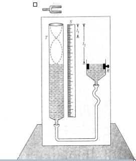
shown figure the setup of a resonance the experiment. There is a long tube T in which initially water is filled upto the top and the rear level can be change by moving a reservoir R up and down.
A tuning fork of known frequency n0 is struck gently on a rubber pad and brought near the open and tube T due to which oscillations are transferred to the air colomn in the tube above water level. Now we gradually decrease the water level in the tube. This air column behaves like a closed organ pipe and the water level as closed end of pipe. As soon as water level reaches a position where there is a node of corresponding stationary wave, in air column, resonance takes place and maximum sound intensity is detected. Let at this position length of air column be I1. If water level is further decreased, again maximum sound intensity is observed when water level is at another node i.e. at a length l2 as shown in figure. Here if we find two successive resonance lengths l1 and l2, we can get the wavelength of the wave as
l2 - l1 = 
or 
Thus sound velocity in air can be given as

Ex.2 A tube of certain diameter and of length 48 cm is open at both ends. Its fundamental frequency of resonance is found to be 320 Hz. The velocity of sound in air is 320 m/s. Estimate the diameter of the tube. One end of the tube is now closed. Calculate the lowest frequency of resonance for the tube.
Sol. The displacement curves of longitudinal waves in a tube open at both ends is shown in figure (a) and (b).


Let r be the radius of the tube. We know the anti-nodes occur slightly outside the tube at a distance 0.6 r from the tube end.
The distance between two anti-nodes is given by

we have 
or 50 = 48 +1.2
or 
Thus diameter of the tube is D = 2r = 3,33
When one end is closed, then

or 
Now 
9.5 Quink's Tube
This is an apparatus used to demonstrate the phenomenon of interference and also used to measure velocity of sound in air. This is made up of two U-tubes A and B as shown in figure. Here the tube B can slide in and out from the tube A. There are two openings P and Q in the tube A. At opening P, a tuning fork or a sound source of known frequency n0 is placed and at the other opening a detector is placed to detect the resultant sound of interference occurred due to superposition of two sound waves coming from the tubes A and B.

Initially tube B is adjusted so that detector detects a maximum. At this instant if length of paths covered by the two waves from P to Q from the side of A and side of B are l1 are l2 respectively then for constructive interference we must have
l2 - l2 = Nl ...(1)
If now tube B is further pulled out by a distance x so that next maximum is obtained and the length of path from the side of B is then we have
 ...(2)
Where x is the displacement of the tube. For next constructive interference of sound at point Q, we have
 ..(3)
..(3)
From equation (1), (2) and (3), we get
or x =  ...(4)
Thus by experiment we get the wavelength of sound as for two successive points of constructive interference, the path difference must be l. As the tube B is pulled out by x, this introduces a path difference 2x in the path of sound wave through tube B. If the frequency of the source is known, n0, the velocity of sound in the air filled in tube can be given as
 ....(5)
Ex.3 In a large room a person receives direct sound waves from a source 120 m away from him. he also receives waves from the same source which reach him, being reflected from the 25m high ceiling at a point halfway between them. For which wavelength will these two sound waves interfere constructivity?
Sol. As shown in figure for reflection from the ceiling
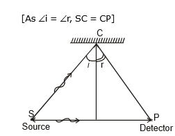
Path SCP = SC + CP = 2SC [As Ði = Ðr, SC = CP]
or Path SCP =  = 130 cm
So path difference between interfering waves
along path SCP, and SP,
Dx = 130 -120 = 10 m
Now for constructive interference at P.
Dx = nl. i.e., 10 = nl
or l =  with n = 1, 2, 3 .........
i.e. l = 10 m, 5m, (10/3) m and so on
Ex.4 Figure shown a tube structure in which a sound signal is sent from one end and is received at the other end. The semicircular part has a radius of 20.0 cm. The frequency of the sound source can be varied electronically between 1000 and 4000 Hz. Find the frequencies at which maxima of intensity are detected. The speed of sound in air = 340 m/s.

Sol. The sound wave reaches detector by two paths simultaneously be straight as well as semicircular track. The wave through the straight path travels a distance l1 = 2 × 20 cm and the wave through the curved part travels a distance l2 = p (20 cm) = 62.8 cm before they meet again and travel to the receiver. The path difference between the two waves received is, therefore,
Dl = l2 - l2 = 62.8 cm - 40 cm = 22.8 cm = 0.228 m
The wavelength of either wave is  =
=  . For constructive interference, Dl = Nl, where N is an integer.
or, 
or, n =  = N(1491.2) Hz = N(1490) Hz
Thus, the frequencies within the specific range which cause maxima of intensity are 1490 Hz and 2980 Hz.
Ex.5 Two sources S1 and S2, separated by 2.0 m, vibrate according to equation y1 = 0.03 sin p t and y2 = 0.02 sin pt where y1, y2 and t are in M.K.S unit. They send out waves of velocity 1.5m/s. Calculate the amplitude of the resultant motion of the particle co-linear with S1 and S2 and located at a point (a) to the right of S2(b) to the left of S2 and (C) in the middle of S1 and S2.
Sol. The situation of shown in figure

The oscillations y1 and y2 have amplitudes A1 = 0.03 m and A2 = 0.02 respectively.
The frequency of both sources in n =  =
=  = 0.5 Hz
Now wavelength of each wave l = =
=  = 3.0 m
(a) The path difference for all points P2 to the right of S2 is
Phase difference  Path difference
The resultant amplitude for this point is given by


Solving we get R = 0.0265 m
(b) The path difference for all point P, to the left of S1
D = (S2P - S1P) = S1S2 = 2.0 m
Hence the resultant amplitude for all points to the left of S1 is also 0.0265 m
(c) For a point Q, between S1 and S2, the path difference is zero i.e., f = 0. Hence constructive interference take place at Q, thus amplitude at this point is maximum and given as
 = A1 A2 = 0.03 0.02 = 0.05 m
Ex.6 Two point sources of sound are placed at a distance d and a detector moves on a straight line parallel to the line joining the sources as shown in figure. at a distance D away from sources. Initially Detector is situated on the line so that it is equidistant from both the sources. Find the displacement of detector when it detects nth maximum sound and also find its displacement when it detects nth minimum sound.

Sol. The situation is shown in figure
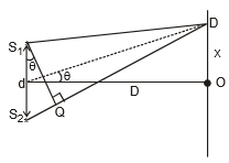
Let us consider the situation when detector move by a distance x as shown. Let at this position the path difference between the waves from S1 and S2 to detector by D then we have
 [Where S1Q is perpendicular on line S;D]
Here if S is small angle as D >> d, we have
Thus at the position of detector, path deference is .....(1)
The expression for path difference in equation (1) is an important formula for such problems. Students are advised to keep this formula in mind for future use.
When detector was at point O, path difference was zero and it detects a maxima, now if detector detects nth maximum then its path difference at a distance x from O can be given as

Similarly if detector detects nth minima then the path difference between two waves at detector can be given as
 or
or 
Ex.7 Two coherent narrow slits emitting of wavelength l in the same phase are placed parallel to each other at a small separation of 2l. the sound is detected by moving a detector on the screen S at a distance D (>> l) from the slit S1 as shown in figure. Find the distance x such that the intensity at P is equal to the intensity at O.

Sol. When detector is at O, we can see that the path difference in the two waves reaching O is d = 2l thus at O detector receives a maximum sound. When it reaches P and again there is a maximum sound detected at P the path difference between two waves must D = l. Thus shown figure the path difference at P can be given as
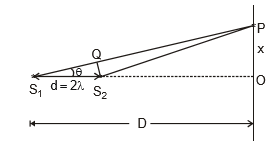

And we have at point P, path difference Δ = λ, Thus
Δ = 21 cos θ = λ
or, 
or 

Thus the value of x can be written as
Ex.8 Figure shown two coherent sources S1 and S2 which emit sound of wavelength l in phase. The separation between the sources is 3l. A circular wire of large radius is placed in such a way that S1S2 lies in its plane and the middle point of S1S2 is at the centre of the wire. Find the angular position q on the wire for which constructive interference takes place.
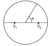
Sol.

From previous question, we can say that for a point P on the circle shown in fiure shown. The path difference in the two waves at P is
Δ = S1P - S2P = d cos θ = 3λ cos θ
We know for constructive interference at P. The path difference must be an integral multiple of wavelength l. Thus for a maxima at P, we have
3λ, cos θ = 0; 3λ. cos θ = λ ; 3λ- cos θ = 2λ. ; 3λ. cos θ = 3λ
or 
 or θ = 0
There are four points A, B, C and D on circle at which q = 0 or and there are two points in each quadrant at  and q =
  at which constructive interference takes place. Thus there are total twelve points on circle at which maxima occurs.
9.6 Vibrations of Clamped Rod
We have discussed the resonant vibrations of a string clamped at two ends. Now we discuss the oscillations of a rod clamped at a point on its length as shown in figure. Figure shows a rod AB clamped at its middle point. If we gently hit the rod at its one end, it begin to oscillate and in the natural oscillations the rod vibrates at its lowest frequency and maximum wavelength, which we call fundamental mode of oscillations. With maximum wavelength when transverse stationary waves setup in the rod, the free ends vibrates as anti-nodes and the clamped end a node as shown in figure. Here if l be the wavelength of the wave, we have
l =  or l =2l

Thus the frequency of fundamental oscillations of a rod damped at mid point can be given as
 ...(1)
Where Y is the Young's modulus of the material of rod and r is the density of the material of rod.
Next higher frequency at which rod vibrates will be then one when wave length is decreased to a value so that one node is inserted between mid point and an end of rod as shown in figure

In this case if l be the wavelength of the waves in rod, we have
l = 
or  ...(2)
Thus in this case the oscillation frequency of rod can be given as
 ...(3)
This is called first overtone frequency of the damped rod or third harmonic frequency. Similarly, the next higher frequency of oscillation i.e. second overtone of the oscillating rod can be shown in figure shown. Here is l be the wavelength of the wave then it can be given as
 or
or  ...(4)

Thus the frequency of oscillation of rod can be given as
 ..(5)
..(5)
Thus the second overtone frequency is the fifth harmonic of the fundamental oscillation frequency of rod. We can also see from the above analysis that the resonant frequencies at which stationary waves are setup in a damped rod are only odd harmonics of fundamental frequency.
Thus when an external source of frequency matching with any of the harmonic of the damped rod then stationary waves are setup in the rod.
9.7 Natural Oscillation of Organ Pipes
When we initiate some oscillations in an organ pipe, which harmonics are excited in the pipe depends on how initial disturbance is produced in it. For example, if you gently blow across the top of an organ pipe it resonates softly at its fundamental frequency. But if you blow must harder you hear the higher pitch of an overtone because the faster air-stream higher frequencies in the exciting disturbance. This sound effect can also be achieved by increasing the air pressure to an organ pipe.
9.8 Kundt's Tube
This is an apparatus used to find velocity of sound in a gaseous medium or in different materials. It consists of a glass tube as shown in figure. one end of which a piston B is fitted which is attached to a wooden handle H and can be moved inside and outside the tube and fixed, the rod M of the required material is fixed at clamp C in which the velocity of sound is required, at one end of rod a disc A is fixed as shown.

In tube air is filled at room temperature and a thin layer of lycopodium powder is put along the length of the tube. It is a very fine powder particles of which can be displaced by the air particles also.
When rod M is gently rubbed with a resin cloth or hit gently, it starts oscillating in fundamental mode as shown in figure, frequency of which can be given as
 [As l0 =
  ]
]

|
199 videos|422 docs|281 tests
|
FAQs on Types: Waves - Physics for Airmen Group X - Airforce X Y / Indian Navy SSR
| 1. What are the different types of waves? |  |
| 2. How do mechanical waves differ from electromagnetic waves? |  |
| 3. What is the difference between transverse waves and longitudinal waves? |  |
| 4. What are some examples of surface waves? |  |
| 5. How do waves transfer energy? |  |

|
Explore Courses for Airforce X Y / Indian Navy SSR exam
|

|


