Overview: Generation, Transmission & Distribution of Electric Power | Basic Electrical Technology - Electrical Engineering (EE) PDF Download
| Table of contents |

|
| Goals of the Lesson |

|
| Introduction |

|
| Basic Idea of Generation |

|
| Transmission of Power |

|
| Distribution System |

|
| Conclusion |

|
Goals of the Lesson
After going through the lesson, you shall get a broad idea of the following:- Different methods of generating electrical power.
- Issues involved in transporting this power to different types of consumers are located generally in far-off places from the generating stations.
- The necessity of substations to cater power to consumers at various voltage levels.
Introduction
In this lesson, a brief idea of a modern power system is outlined. Emphasis is given to create a clear mental picture of a power system to a beginner of the course ElectricalTechnology.
As consumers, we use electricity for various purposes such as:
- Lighting, heating, cooling and other domestic electrical appliances used at home.
- Street lighting, floodlighting of the sporting arena, office building lighting, powering PCs etc.
- Irrigating vast agricultural lands using pumps and operating cold storages for various agricultural products.
- Running motors, furnaces of various kinds, in industries.
- Running locomotives (electric trains) of railways.
The list above is obviously not exhaustive and could be expanded and categorized in detail further. The point is, without electricity, modern-day life will simply come to a stop. In fact, the advancement of a country is measured by the index per capita consumption of electricity – i.e. the more it is, the more advanced the country is.
Basic Idea of Generation
- Prior to the discovery of Faraday’s Laws of electromagnetic induction, electrical power was available from batteries with limited voltage and current levels.
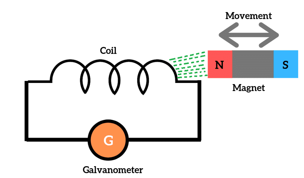 Faraday's Law of Electromagnetic Induction
 - Although complicated in construction, D.C generators were developed first to generate power in bulk. However, due to limitation of the D.C machine to generate voltage beyond a few hundred volts, it was not economical to transmit a large amount of power over a long distance. For a given amount of power, the current magnitude (I = P/V), hence section of the copper conductor will be large.
- Thus generation, transmission and distribution of D.C power were restricted to an area of few kilometre radii with no interconnections between generating plants. Therefore, area-specific generating stations along with its distribution networks, had to be used.
Change over from D.C to A.C
- In the later half of the eighties, in the nineteenth century, it was proposed to have a power system with 3- phase, 50 Hz A.C generation, transmission and distribution networks. Once A.C system was adopted, the transmission of large power (MW) at higher transmission voltage become a reality by using transformers.
- Level of voltage could be changed virtually to any other desired level with transformers – which was hitherto impossible with D.C system.
- Nicola Tesla suggested that constructionally simpler electrical motors (induction motors, without the complexity of commutator segments of D.C motors) operating from 3-phase A.C supply could be manufactured. In fact, his arguments in favour of A.C supply system own the debate on switching over from D.C to A.C system.
A.C Generator
- A.C power can be generated as a single-phase or as a balanced poly-phase system. However, it was found that 3-phase power generation at 50 Hz will be economical and most suitable.
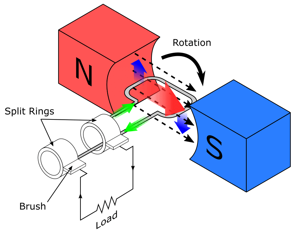 Synchronous AC Generator
 - In present-day three-phase generators, used to generate 3-phase power are called alternators (synchronous generators). An alternator has a balanced three-phase winding on the stator and called the armature. The three coils are so placed in space that their axes are mutually 120° apart, as shown in figure below. From the terminals of the armature, 3-phase power is obtained.
- Rotor houses a field coil and excited by D.C. The field coil produces flux and electromagnetic poles on the rotor surface. If the rotor is driven by an external agency, the flux linkages with three stator coils become a sinusoidal function of time and sinusoidal voltage is induced in them.
- However, the induced voltages in the three coils (or phases) will differ in phase by 120° because the present value of flux linkage with R-phase coil will take place after 120° with Y-phase coil and further 120° after, with B-phase coil.
- A salient pole alternator has projected poles, as shown in figure (a). It has a non-uniform air gap and is generally used where speed is low. On the other hand, a non salient pole alternator has uniform air gap (figure (b)) and used when speed is high.
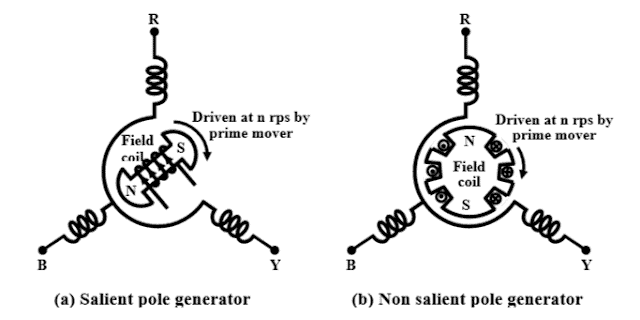 3-Phase Generators
Frequency, Voltage & Interconnected System
- The frequency of the generated emf for a 'p' polar generator is given by f = (p/120).n where 'n' is the speed of the generator in rps or f = (p/2).n when 'n' is in rpm. Frequency of the generated voltage is standardized to 50 HZ in our country and several European countries.
- In USA and Canada it is 60 Hz. The following table gives the rpm at which the generators with a different number of poles are to be driven in order to generate 50 Hz voltage.
- A modern power station has more than one generator and these generators are connected in parallel. Also, there exist a large number of power stations spread over a region or a country. A regional power grid is created by interconnecting these stations through transmission lines. In other words, all the generators of different power stations, in a grid are in effect connected in parallel.
- One of the advantages of interconnection is obvious; suppose due to technical problem the generation of a plant becomes nil or less, then a portion of the demand of power in that area still can be made from the other power stations connected to the grid. One can thus avoid complete shut down of power in an area in case of technical problem in a particular station.
- It can be shown that in an interconnected system, with more number of generators connected in parallel, the system voltage and frequency tend to fixed values irrespective of the degree of loading present in the system. This is another welcome advantage of an interconnected system.
- An interconnected system, however, is to be controlled and monitored carefully as they may give rise to instability leading to collapse of the system.
- All electrical appliances (fans, refrigerator, TV etc.) to be connected to A.C supply are therefore designed for a supply frequency of 50 Hz. Frequency is one of the parameters which decides the quality of the supply. It is the responsibility of the electric supply company to see that frequency is maintained close to 50 Hz at the consumer premises.
- It was pointed out earlier that a maximum of few hundreds of volts (say about 600 to 700 V) could be developed in a D.C generator, the limitation is imposed primarily due to presence of commutator segments.
- In the absence of commutators, the present-day generated voltage in the alternator is much higher, typically around 10 kV to 15 kV. It can be shown that RMS voltage induced in a coil is proportional to φ and n i.e.,
Ecoil ∝ φ n, where φ is the flux per pole and n is the speed of the alternator. - This can be justified by intuition as well: we know that mere rotating a coil in the absence of magnetic flux (φ) is not going to induce any voltage. Also, the presence of flux without any rotation will fail to induce any voltage as you require a rate of change of flux linkage in a coil. To control the induced voltage one has to control the d.c field current as the speed of the alternator gets fixed by frequency constrain.
Thermal, Hydel & Nuclear Power Stations
In this section, we briefly outline the basics of the three most widely found power generating stations - Thermal, Hydel and Nuclear plants in our country and elsewhere.
1. Thermal Power Plant
- We have seen in the previous section that to generate a voltage at 50 Hz, we have to run the generator at some fixed rpm by some external agency. A turbine is used to rotate the generator. The turbine may be of two types, namely steam turbine and water turbine.
- In a thermal power station, coal is burnt to produce steam which in turn, drives the steam turbine hence the generator (turbo set). In figure below, the elementary features of a thermal power plant are shown.
- In a thermal power plant coil is burnt to produce high temperature and high-pressure steam in a boiler. The steam is passed through a steam turbine to produce rotational motion. The generator, mechanically coupled to the turbine, thus rotates producing electricity.
- Chemical energy stored in coal after a couple of transformations produces electrical energy at the generator terminals as depicted in the figure. Thus proximity of a generating station nearer to a coal reserve and water sources will be most economical as the cost of transporting coal gets reduced.
- In our country coal is available in abundance and naturally thermal power plants are most popular. However, these plants pollute the atmosphere because of the burning of coals.
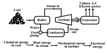 Basic Components of a Thermal Generating Unit
- Stringent conditions (such as the use of more chimney heights along with the compulsory use of electrostatic precipitator) are put by regulatory authorities to see that the effects of pollution are minimized. A large amount of ash is produced every day in a thermal plant and effective handling of the ash adds to the running cost of the plant.
- Nonetheless, 57% of the generation in our country is from thermal plants. The speed of alternator used in thermal plants is 3000 rpm which means 2-pole alternators are used in such plants.
2. Hydel Power Plants
- In a hydel power station, water head is used to drive a water turbine coupled to the generator. Water head may be available in the hilly region naturally in the form of the water reservoir (lakes etc.) at the hilltops.
- The potential energy of water can be used to drive the turbo-generator set installed at the base of the hills through piping called penstock. Water head may also be created artificially by constructing dams on a suitable river.
- In contrast to a thermal plant, hydel power plants are eco-friendly, neat and clean as no fuel is to be burnt to produce electricity. While running cost of such plants is low, the initial installation cost is rather high compared to a thermal plant due to massive civil construction necessary.
- Also, sites to be selected for such plants depend upon natural availability of water reservoirs at hilltops or availability of suitable rivers for constructing dams. Water turbines generally operate at low rpm, so the number of poles of the alternator are high. For example, in a 20-pole alternator, the rpm of the turbine is only 300 rpm.
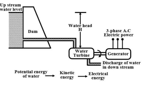 Basic Components of a Hydel Generating Unit
3. Nuclear Power Plants
- As coal reserve is not unlimited, there is a natural threat to thermal power plants based on coal. It is estimated that within the next 30 to 40 years, coal reserve will exhaust if it is consumed at the present rate.
- Nuclear power plants are thought to be the solution for bulk power generation. At present, the installed capacity of a nuclear power plant is about 4300 MW and expected to expand further in our country. The present-day atomic power plants work on the principle of nuclear fission of 235U.
- In the natural uranium, 235U constitutes only 0.72% and remaining parts are constituted by 99.27% of 238U and only about 0.05% of 234U. The concentration of 235U may be increased to 90% by gas diffusion process to obtain enriched 235U. When 235U is bombarded by neutrons a lot of heat energy along with additional neutrons are produced.
- These new neutrons further bombard 235U producing more heat and more neutrons. Thus a chain reaction sets up. However, this reaction is allowed to take place in a controlled manner inside a closed chamber called nuclear reactor.
- To ensure sustainable chain reaction, moderator and control rods are used. Moderators such as heavy water (deuterium) or very pure carbon 12C are used to reduce the speed of neutrons.
- To control the number of neutrons, control rods made of cadmium or boron steel are inserted inside the reactor. The control rods can absorb neutrons. If we want to decrease the number of neutrons, the control rods are lowered down further and vice versa.
- The heat generated inside the reactor is taken out of the chamber with the help of a coolant such as liquid sodium or some gaseous fluids. The coolant gives up the heat to water in the heat exchanger to convert it to steam. The steam then drives the turbo set and the exhaust steam from the turbine is cooled and fed back to the heat exchanger with the help of the water feed pump.
- The calculation shows that to produce 1000 MW of electrical power in coal-based thermal plant, about 6 × 10⁶ Kg of coal is to be burnt daily while for the same amount of power, only about 2.5 Kg of 235U is to be used per day in a nuclear power station.
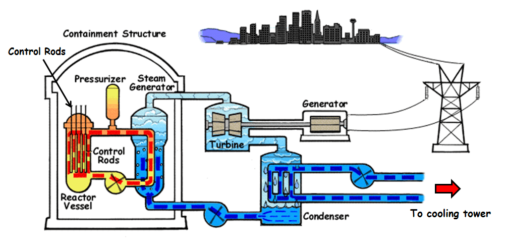 Nuclear Power Generation
- The initial investment required to install a nuclear power station is quite high but the running cost is low. Although nuclear plants produce electricity without causing air pollution, it remains a dormant source of radiation hazards due to leakage in the reactor. Also, the used fuel rods are to be carefully handled and disposed off as they still remain radioactive.
- The reserve of 235U is also limited and can not last long if its consumption continues at the present rate. Naturally, search for alternative fissionable material continues. For example, plutonium (239Pu) and (233U) are fissionable. However, they are not directly available.
- Absorbing neutrons, 238U gets converted to fissionable plutonium 239Pu in the atomic reactor described above. The used fuel rods can be further processed to extract 239Pu from it indirectly increasing the availability of fissionable fuel.
- An effort is also on to convert thorium into fissionable 233U. Incidentally, India has a very large reserve of thorium in the world. Total approximate generation capacity and Contribution by thermal, hydel and nuclear generation in our country are given below.
Non-Conventional Sources of Energy
- The bulk generation of power by thermal, hydel and nuclear plants are called conventional methods for producing electricity. Search for newer avenues for harnessing eco-friendly electrical power has already begun to meet the future challenges of meeting growing power demand.
- Compared to conventional methods, the capacity in terms of MW of each non-conventional plant is rather low, but most of them are eco friendly and self-sustainable. Wind power, solar power, MHD generation, fuel cell and power from tidal waves are some of the promising alternative sources of energy for the future.
Transmission of Power
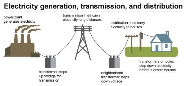
- The huge amount of power generated in a power station (hundreds of MW) is to be transported over a long distance (hundreds of kilometres) to load centres to cater power to consumers with the help of transmission line and transmission towers as shown in figure 2.5.
- To give an idea, let us consider a generating station producing 120 MW power and we want to transmit it over a large distance. Let the voltage generated (line to line) at the alternator be 10 kV. Then to transmit 120 MW of power at 10 kV, current in the transmission line can be easily calculated by using power formula circuit (which you will learn in the lesson on A.C circuit analysis) for 3-phases follows:
- Instead of choosing 10 kV transmission voltage, if transmission voltage were chosen to be 400 kV, the current value in the line would have been only 261.5 A. So sectional area of the transmission line (copper conductor) will now be much smaller compared to 10 kV transmission voltage.
- In other words, the cost of the conductor will be greatly reduced if power is transmitted at higher and higher transmission voltage. The use of higher voltage (hence lower current in the line) reduces voltage drop in the line resistance and reactance. Also, transmission losses are reduced. Standard transmission voltages used are 132 kV or 220 kV or 400 kV or 765 kV depending upon how long the transmission lines are.
- Therefore, after the generator, we must have a step-up transformer to change the generated voltage (say 10 kV) to desired transmission voltage (say 400 kV) before transmitting it over a long distance with the help of transmission lines supported at regular intervals by transmission towers.
- It should be noted that while the magnitude of the current decides the cost of copper, the level of voltage decides the cost of insulators. The idea is, in a spree to reduce the cost of copper, one can not indefinitely increase the level of transmission voltage as cost of insulators will offset the reduction copper cost. At the load centres, voltage level should be brought down at suitable values for supplying different types of consumers.
Consumers may be:
(i) big industries, such as steel plants.
(ii) medium and small industries.
(iii) offices and domestic consumers. - Electricity is purchased by different consumers at a different voltage level. For example, big industries may purchase power at 132 kV, medium and big industries purchase power at 33 kV or 11 kV and domestic consumers at a rather low voltage of 230V, single phase. Thus we see that 400 kV transmission voltage is to be brought down to different voltage levels before finally delivering power to different consumers. To do this, we require obviously step down transformers.
Substations
- Substations are the places where the level of voltage undergoes change with the help of transformers. Apart from transformers, a substation will house switches (called circuit breakers), meters, relays for protection and other control equipment.
- Broadly speaking, a big substation will receive power through incoming lines at some voltage (say 400 kV) changes the level of voltage (say to 132 kV) using a transformer and then directs it outwards through outgoing lines. Pictorially such a typical power system is shown in the figure below.
- At the lowest voltage level of 400 V, generally 3-phase, 4-wire system is adopted for domestic connections. The fourth wire is called the neutral wire (N) which is taken out from the common point of the star-connected secondary of the 6 kV/400 V distribution transformer.
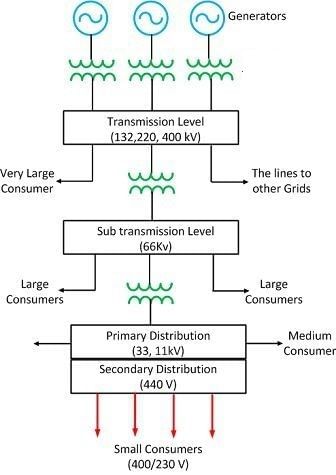 Power Supply System
Some important components/equipments in substation:
(i) Distribution Transformer
(ii) Circuit breaker
(iii) Lightning Arrester
(iv) Air Break (AB) switches / Isolator
(v) Insulator
(vi) Busbar
(vii) Capacitor Bank
(viii) Earthing
(ix) Fencing
(x) Distribution panel board
- As told earlier, the function of a substation is to receive power at some voltage through incoming lines and transmit it at some other voltage through outgoing lines. So the most important equipment in a substation is transformer(s). However, for flexibility of operation and protection transformer and lines, additional equipments are necessary.
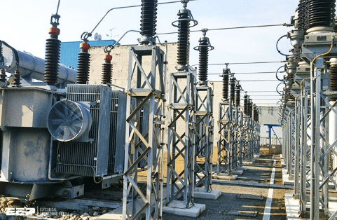 Transformer
 - Suppose the transformer goes out of order and maintenance work is to be carried out. Naturally, the transformer must be isolated from the incoming as well as from the outgoing lines by using a special type of heavy-duty (high voltage, high current) switches called circuit breakers.
- Thus a circuit breaker may be closed or opened manually (functionally somewhat similar to switching on or off a fan or a light whenever desired with the help of an ordinary switch in your house) in substation whenever desired.
- However, unlike an ordinary switch, a circuit breaker must also operate (i.e., become opened) automatically whenever a fault occurs or overloading takes place in a feeder or line.
- To achieve this, we must have a current sensing device called CT (current transformer) in each line. A CT simply steps down the large current to a proportional small secondary current. Primary of the CT is connected in series with the line. A 1000 A/5 A CT will step down the current by a factor of 200. So if the primary current happens to be 800 A, secondary current of the CT will be 4 A.
- Suppose the rated current of the line is 1000 A, and due to any reason, if current in the line exceeds this limit, we want to operate the circuit breaker automatically for disconnection.
- In figure 2.7, the basic scheme is presented to achieve this. The secondary current of the CT is fed to the relay coil of an overcurrent relay. Here we are not going into constructional and operational details of an overcurrent relay but try to tell how it functions.
- Depending upon the strength of the current in the coil, an ultimate electromagnetic torque acts on an aluminium disc restrained by a spring. Spring tension is so adjusted that for normal current, the disc does not move.
- However, if the current exceeds the normal value, torque produced will overcome the spring tension to rotate the disc about a vertical spindle to which a long arm is attached. To the arm, a copper strip is attached as shown in figure 2.8. Thus the arm too will move whenever the disk moves.
- The relay has a pair of normally opened (NO) contacts 1 & 2. Thus, there will exist an open circuit between 1 & 2 with the normal current in the power line.
- However, during fault condition in the line or overloading, the arm moves in the anticlockwise direction till it closes the terminals 1 & 2 with the help of the copper strip attached to the arm as explained pictorially in figure 2.8. This short circuit between 1 & 2 completes a circuit comprising of a battery and the trip coil of the circuit breaker.
- The opening and closing of the main contacts of the circuit breaker depend on whether its trip coil is energized or not. It is interesting to note that the trip circuit supply is to be made independent of the A.C. supply derived from the power system we want to protect. For this reason, we expect batteries along with a battery charger to be present in a substation.
- Apart from above, there will be other types of protective relays and various meters indicating current, voltage, power etc.
- To measure and indicate the high voltage (say 6 kV) of the line, the voltage is stepped down to a safe value (say 110V) by transformer called potential transformer (PT). Across the secondary of the PT, MI type indicating voltmeter is connected. For example, a voltage rating of a PT could be 6000 V/110 V. Similarly, across the secondary, we can connect a low range ammeter to indicate the line current.
Single Line Representation of Power System
- Trying to represent a practical power system where a lot of interconnections between several generating stations involving a large number of transformers using three lines corresponding to R, Y and B phase will become unnecessary clumsy and complicated.
- To avoid this, a single line along with some symbolical representations for generator, transformers substation buses are used to represent a power system rather neatly. For example, the system shown in 2.6 with three lines will be simplified to figure 2.9 using a single line.
- As another example, an interconnected power system is represented in the self-explained figure 2.10 – it is hoped that you understand the important features communicated about the system through this figure.
Distribution System
- Till now we have learnt how power at somewhat high voltage (say 33 kV) is received in a substation situated near the load centre (a big city). The loads of a big city are primarily residential complexes, offices, schools, hotels, street lighting etc.
- These types of consumers are called LT (low tension) consumers. Apart from this, there may be medium and small scale industries located in the outskirts of the city. LT consumers are to be supplied with single-phase, 220 V, 40 Hz. We shall discuss here how this is achieved in the substation receiving power at 33 kV. The scheme is shown in figure 2.11.
- Power received at a 33 kV substation is first stepped down to 6 kV and with the help of underground cables (called feeder lines), power flow is directed to different directions of the city. At the last level, step down transformers are used to step down the voltage from 6 kV to 400 V. These transformers are called distribution transformers with 400 V, star-connected secondary.
- You must have noticed such transformers mounted on poles in cities besides the roads. These are called pole-mounted substations. From the secondary of these transformers 4 terminals (R, Y, B and N) come out. N is called the neutral and taken out from the common point of star-connected secondary.
- The voltage between any two phases (i.e., R-Y, Y-B and B-R) is 400 V and between any phase and neutral is 230 V = 400/(√3). Residential buildings are supplied with single-phase 230V, 50Hz. So individual are to be supplied with any one of the phases and neutral.
- Supply authority tries to see that the loads remain evenly balanced among the phases as far as possible. Which means roughly one-third of the consumers will be supplied from R-N, next one third from Y-N and the remaining one third from B-N.
- The distribution of power from the pole-mounted substation can be done either by:
(i) overhead lines (bare conductors)
(ii) underground cables - Use of overhead lines, although cheap, is often accident-prone and also the theft of power by hooking from the lines take place. Although costly, in big cities and thickly populated areas, underground cables for distribution of power, are used.
Conclusion
- In this lesson, a brief idea of generation, transmission and distribution of electrical power is given - which for obvious reason is neither very elaborative nor exhaustive.
- Nonetheless, it gives a reasonable understanding of the system for a beginner going to undertake the course on electrical technology. If you ever get a chance to visit a substation or power station – don’t miss it.
Some basic and important points, in relation to a modern power system, are summarized below:
- Generation, transmission and distribution of electric power in our country is carried out as a 3-phase system at 50 Hz.
- Three most important conventional methods of power generation in our country are:
(i) Coal-based thermal plants
(ii) Hydel plants
(iii) Nuclear plants - Load centres (where the power will be actually consumed) are in general situated far away from the generating station. So to transmit a large amount of power (hundreds of MW) efficiently and economically over a long distance, high transmission voltage (such as 400 kV, 220 kV) is used.
- The material used for transmission lines is bare copper conductors which are supported at regular intervals by steel towers. Stack of disk type ceramic insulators is used between the HV line and the steel tower.
- Level of current decides the section of the line conductor and the level of voltage decides the amount of insulation required.
|
75 docs|62 tests
|
FAQs on Overview: Generation, Transmission & Distribution of Electric Power - Basic Electrical Technology - Electrical Engineering (EE)
| 1. What is the basic idea of generation in the context of electrical power? |  |
| 2. What is the transmission of power in the context of electrical power? |  |
| 3. What is the distribution system in the context of electrical power? |  |
| 4. What are the different sources of electrical power generation? |  |
| 5. What is the importance of electrical power in our daily lives? |  |

