Ideal Transformer | Basic Electrical Technology - Electrical Engineering (EE) PDF Download
Goals of the Lesson
- In this lesson, we shall study two winding ideal transformer, its properties and working principle under no-load condition as well as under load condition.
- Induced voltages in primary and secondary are obtained, clearly identifying the factors on which they depend.
- The ratio between the primary and secondary voltages are shown to depend on the ratio of turns of the two windings.
- How to draw phasor diagram under no-load and load conditions, are explained.
- Importance of studying such a transformer will be highlighted.
- In the end, several objective type and numerical problems have been given for solving.
Keywords: Magnetising current, HV & LV windings, no load phasor diagram, reflected current, equivalent circuit.
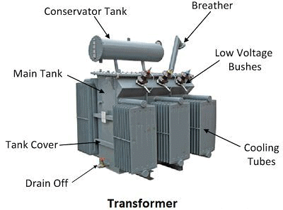
After going through this section, students will be able to understand the following:
- Necessity of transformers in a power system.
- Properties of an ideal transformer.
- Meaning of load and no-load operation.
- Basic working principle of operation under no-load condition.
- No-load operation and phasor diagram under no load.
- The factors on which the primary and secondary induced voltages depend.
- Fundamental relations between primary and secondary voltages.
- The factors on which peak flux in the core depend.
- The factors which decide the magnitude of the magnetizing current.
- What does the loading of a transformer mean?
- What is reflected current and when does it flow in the primary?
- Why does VA (or kVA) remain the same on both sides?
- What impedance does the supply see when a given impedance Z2 is connected across the secondary?
- Equivalent circuit of an ideal transformer referred to different sides.
Introduction
- Transformers are one of the most important components of any power system. It basically changes the level of voltages from one value to the other at a constant frequency. Being a static machine, the efficiency of a transformer could be as high as 99%.
- Big generating stations are located hundreds or more km away from the load centre (where the power will be actually consumed). Long transmission lines carry the power to the load centre from the generating stations. A generator is a rotating machine and the level of voltage at which it generates power is limited to several kilovolts only – a typical value is 11 kV.
- To transmit a large amount of power (several thousands of megawatts) at this voltage level means a large amount of current has to flow through the transmission lines. The cross-sectional area of the conductor of the lines accordingly should be large. Hence the cost involved in transmitting a given amount of power rises many folds.
- Not only that, the transmission lines have their own resistances. This huge amount of current will cause a tremendous amount of power loss or I2r loss in the lines. This loss will simply heat the lines and becomes wasteful energy. In other words, the efficiency of transmission becomes poor and the cost involved is high.
- The above problems may be addressed if we could transmit power at a very high voltage say, at 200 kV or 400 kV or even higher at 800 kV. But as pointed out earlier, a generator is incapable of generating a voltage at these level due to its own practical limitation.
- The solution to this problem is to use an appropriate step-up transformer at the generating station to bring the transmission voltage level to the desired value as depicted in the figure below where for simplicity single-phase system is shown to understand the basic idea.
 A Simple Single Phase Power System
- Obviously, when power reaches the load centre, one has to step down the voltage to suitable and safe values by using transformers. Thus transformers are an integral part of any modern power system.
- Transformers are located in places called substations. In cities or towns, you must have noticed transformers are installed on poles – these are called pole-mounted distribution transformers. These type of transformers change voltage level typically from 3-phase, 6 kV to 3-phase 440 V line to line.
- In this and the following lessons, we shall study the basic principle of operation and performance evaluation based on the equivalent circuit.
Principle of Operation
An ideal transformer works on two principles:
(i) Faraday's Law of Electromagnetic Induction
(ii) Mutual Inductionwhen an electric current generates a magnetic field and a changing magnetic field in a coil induces a voltage across the coil ends. When the current is changed within the primary coil, then the magnetic flux is developed. So changing magnetic field can induce a voltage within the secondary coil.
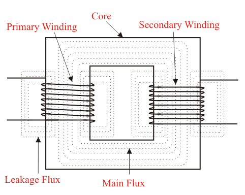
- When the current flows through the primary coil then it creates a magnetic field. The two windings are wrapped in the region of a very high magnetic core like iron, so the magnetic flux supplies through the two windings. Once a load is connected to the secondary coil, then the voltage and current will be in the indicated direction.
Ideal Transformer
- A transformer in its simplest form will consist of a rectangular laminated magnetic structure on which two coils of the different number of turns are wound as shown in Figure 23.2.
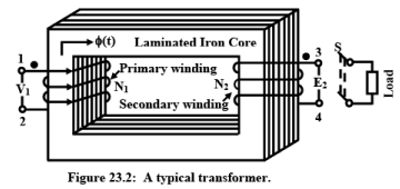
- The winding to which a.c voltage is impressed is called the primary of the transformer and the winding across which the load is connected is called the secondary of the transformer.
- To understand the working of a transformer, it is always instructive to begin with the concept of an ideal transformer with the following properties:
(i) Primary and secondary windings have no resistance.
(ii) All the flux produced by the primary links the secondary winding i,e., there is no leakage flux.
(iii) Permeability μ r of the core is infinitely large. In other words, to establish flux in the core vanishingly small (or zero) current is required.
(iv) Core loss comprising of eddy current and hysteresis losses are neglected.
➢ Core Flux Gets Fixed by Voltage & Frequency
- The flux level Bmax in the core of a given magnetic circuit gets fixed by the magnitude of the supply voltage and frequency. This important point has been discussed in the previous lecture 20. It was shown that:
 where V is the applied voltage at frequency f, N is the number of turns of the coil and A is the cross-sectional area of the core.
 - For a given magnetic circuit A and N are constants, so Bmax developed in the core is decided by the ratio V/f. The peak value of the coil current Imax, drawn from the supply now gets decided by the B-H characteristics of the core material.
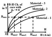 Estimating current drawn for different core materials.
- To elaborate this, let us consider a magnetic circuit with N number of turns and core section area A with mean length l. Let material-3 be used to construct the core whose B-H characteristic shown in figure 23.3. Now the question is, if we apply a voltage V at frequency f, how much current will be drawn by the coil?
- We follow the following steps to arrive at the answer:
(i) First, calculate maximum flux density using Note that value of Bmax is independent of the core material property.
(ii) Corresponding to this Bmax, obtain the value of Hmax3 from the B-H characteristic of the material-3 (figure 23.3).
(iii) Now calculate the required value of the current using the relation (iv) The RMS value of the exciting current with material-3 as the core, will be
- By following the above steps, one could also estimate the exciting currents (I2 or I3) drawn by the coil if the core material were replaced by material-2 or by material-3 with other things remaining same. Obviously current needed, to establish a flux of Bmax is lowest for material-3. Finally note that if the core material is such that μ r →∞ , the B-H characteristic of this ideal core material will be the B axis itself as shown by the thick line in figure 23.3 which means that for such an ideal core material current needed is practically zero to establish any Bmax in the core.
Analysis of Ideal Transformer
- Let us assume a sinusoidally varying voltage is impressed across the primary with secondary winding open-circuited. Although the current drawn Im will be practically zero, but its position will be 90° lagging with respect to the supply voltage. The flux produced will obviously be in phase with Im. In other words, the supply voltage will lead the flux phasor by 90°. Since flux is common for both the primary and secondary coils, it is customary to take flux phasor as the reference.

- The time-varying flux φ(t) will link both the primary and secondary turns inducing in voltages e1 and e2 respectively.
- The instantaneous induced voltage in the primary
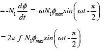
- The instantaneous induced voltage in secondary

- Magnitudes of the RMS induced voltages will therefore be

- The time phase relationship between the applied voltage v1 and e1 and e2 will be the same. The 180° phase relationship obtained in the mathematical expressions of the two merely indicates that the induced voltage opposes the applied voltage as per Lenz’s law. In other words, if e1 were allowed to act alone, it would have delivered power in a direction opposite to that of v1. By applying Kirchoff’s law in the primary one can easily say that V1 = E1 as there is no other drop existing in this ideal transformer.
- Thus under no-load condition,
 Where, V1, V2 are the terminal voltages and E1, E2 are the RMS induced voltages. In convention 1, phasors
  and
and  are drawn 180° out of phase with respect to
  in order to convey the respective power flow directions of these two are opposite. The second convention results from the fact that the quantities v1(t), e1(t) and e2(t) vary in unison, then why not show them as co-phasor and keep remember the power flow business in one’s mind.
No-Load Phasor Diagram
- A transformer is said to be under the no-load condition when no load is connected across the secondary, i.e., the switch S in figure 23.2 is kept opened and no current is carried by the secondary windings. The phasor diagram under no-load condition can be drawn starting with
 as the reference phasor as shown in the figure below.
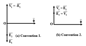 No-load Phasor Diagram
 - In convention 1, phasors
 and
and  are drawn 180° out of phase with respect to
  in order to convey that the respective power flow directions of these two are opposite. The second convention results from the fact that the quantities v1(t), e1(t) and e2(t) vary in unison then why not show them as co-phasor and keep remember the power flow business in one’s mind. Also, remember vanishingly small magnetizing current is drawn from the supply creating the flux and in time phase with the flux.
Transformer Under Loaded Condition
- In this lesson, we shall study the behaviour of the transformer when loaded. A transformer gets loaded when we try to draw power from the secondary. In practice, loading can be imposed on a transformer by connecting impedance across its secondary coil. It will be explained how the primary reacts when the secondary is loaded.
- It will be shown that any attempt to draw current/power from the secondary, is immediately responded by the primary winding by drawing extra current/power from the source. We shall also see that MMF balance will be maintained whenever both the windings carry currents. Together with the MMF balance equation and voltage ratio equation, invariance of Volt-Ampere (VA or KVA) irrespective of the sides will be established.
 Transformer Under Load Condition
- We have seen in the preceding section that the secondary winding becomes a seat of emf and ready to deliver power to a load if connected across it when the primary is energized. Under no-load condition power drawn is zero as current drawn is zero for an ideal transformer. However when loaded, the secondary will deliver power to the load and the same amount of power must be sucked in by the primary from the source in order to maintain power balance.
- We expect the primary current to flow now. Here we shall examine in somewhat detail the mechanism of drawing extra current by the primary when the secondary is loaded. For a fruitful discussion on it let us quickly review the dot convention in mutually coupled coils.
Dot Convention
- The primary of the transformer shown in figure 23.2 is energized from a.c source and potential of terminal 1 with respect to terminal 2 is v12 = Vmax sinωt. Naturally, polarity of 1 is sometimes +ve and some other time it is –ve.
- The dot convention helps us to determine the polarity of the induced voltage in the secondary coil marked with terminals 3 and 4. Suppose at some time t we find that terminal 1 is +ve and it is increasing with respect to terminal 2. At that time, what should be the status of the induced voltage polarity in the secondary – whether terminal 3 is +ve or –ve? If possible, let us assume terminal 3 is –ve and terminal 4 is positive. If that be current the secondary will try to deliver current to a load such that current comes out from terminal 4 and enters terminal 3.
- Secondary winding therefore, produces flux in the core in the same direction as that of the flux produced by the primary. So core flux gets strengthened in inducing more voltage. This is contrary to the dictate of Lenz’s law which says that the polarity of the induced voltage in a coil should be such that it will try to oppose the cause for which it is due. Hence terminal 3 can not be –ve.
- If terminal 3 is +ve, then we find that secondary will drive current through the load leaving from terminal 3 and entering through terminal 4. Therefore flux produced by the secondary clearly opposes the primary flux fulfilling the condition set by Lenz’s law. Thus when terminal 1 is +ve terminal 3 of the secondary too has to be positive.
- In mutually coupled coils, dots are put at the appropriate terminals of the primary and secondary merely to indicate the status of polarities of the voltages. Dot terminals will have at any point of time identical polarities.
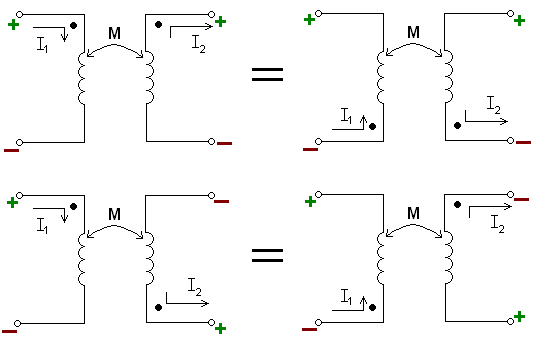 Dot Convention in Ideal Transformer
- In the transformer of figure 23.2, it is appropriate to put dot markings on terminal 1 of primary and terminal 3 of secondary. It is to be noted that if the sense of the windings are known (as in figure 23.2), then one can ascertain with confidence where to place the dot markings without doing any testing whatsoever.
- In practice however, only a pair of primary terminals and a pair of secondary terminals are available to the user and the sense of the winding can not be ascertained at all. In such cases, the dots can be found out by doing some simple tests such as polarity test or d.c kick test.
- If the transformer is loaded by closing the switch S, the current will be delivered to the load from terminal 3 and back to 4. Since the secondary winding carries current, it produces flux in the anti clockwise direction in the core and tries to reduce the original flux.
- However, KVL in the primary demands that core flux should remain constant no matter whether the transformer is loaded or not. Such a requirement can only be met if the primary draws a definite amount of extra current in order to nullify the effect of the MMF produced by the secondary.
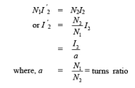
- Let it be clearly understood that net mmf acting in the core is given by: mmf due to vanishingly small magnetizing current + mmf due to secondary current + mmf due to additional primary current. But the last two terms must add to zero in order to keep the flux constant and net mmf eventually be once again be due to vanishingly small magnetizing current. If I2 is the magnitude of the secondary current and I2' is the additional current drawn by the primary then following relation must hold good:
- To draw the phasor diagram under load condition, let us assume the power factor angle of the load to be θ2, lagging. Therefore the load current phasor
 , can be drawn lagging the secondary terminal voltage
  by θ2 as shown in the figure below.
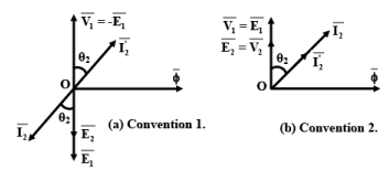 Phasor diagram when transformer is loaded
- The reflected current magnitude can be calculated from the relation I 2' = I2a and is shown directed 180° out of phase with respect to
 in convention 1 or in phase with
  as per the convention 2. At this stage let it be suggested to follow one convention only and we select convention 2 for that purpose. Now, Volt-Ampere delivered to the load= V2I2
= E2I2 = E1I1=V1I1
=Volt-Ampere drawn from the supply. - Thus we note that for an ideal transformer, the output VA is the same as the input VA and also the power is drawn at the same power factor as that of the load.
Equivalent Circuit of an Ideal Transformer
The equivalent circuit of a transformer can be drawn:
(i) Showing both the sides along with parameters.
(ii) Referred to the primary side.
(iii) Referred to the secondary side.
- In whichever way the equivalent circuit is drawn, it must represent the operation of the transformer correctly both under no-load and load condition. The figure below shows the equivalent circuits of the transformer.
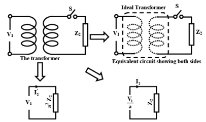 Equivalent circuits of an Ideal Transformer referred to primary and secondary
- Think in terms of the supply. It supplies some current at some power factor when a load is connected in the secondary. If instead of the transformer, an impedance of value a2Z2 is connected across the supply, supply will behave identically. This corresponds to the equivalent circuit referred to the primary.
- Similarly from the load point of view, forgetting about the transformer, we may be interested to know what voltage source should be impressed across Z2 such that same current is supplied to the load when the transformer was present. This corresponds to the equivalent circuit referred to the secondary of the transformer.
- When both the windings are shown in the equivalent circuit, they are shown with chain lines instead of a continuous line. Why? This is because, when the primary is energized and secondary is opened, no current is drawn, however, current is drawn when a load is present on the secondary side. Although supply two terminals are physically joined by the primary winding, the current drawn depends upon the load on the secondary side.
|
75 docs|62 tests
|
FAQs on Ideal Transformer - Basic Electrical Technology - Electrical Engineering (EE)
| 1. What are the goals of the lesson? |  |
| 2. What is an ideal transformer? |  |
| 3. How is the no-load phasor diagram of a transformer determined? |  |
| 4. How does a transformer behave under loaded conditions? |  |
| 5. What is the dot convention in transformer theory? |  |


