Electromagnetic Waves | GATE Notes & Videos for Electrical Engineering - Electrical Engineering (EE) PDF Download

Electromagnetic wave at the interface between two dielectric media
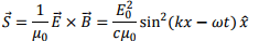
The propagation of electromagnetic wave in an isotropic, homogeneous, dielectric medium, such as in air or vacuum. In this lecture, we woulddiscuss what happens when a plane electromagnetic wave is incident at the interface between two dielectric media. For being specific, we will take one of the medium to be air or vacuum and the other to be a dielectric such as glass. We have come across this in school in connection with the reflection and transmission of light waves at such an interface. In this lecture, we would investigate this problem from the point of view of electromagnetic theory.
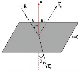
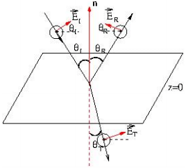
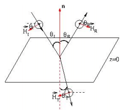
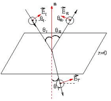
Let us choose the interface to be the xy plane (z=0). The angles of incidence, reflection and refraction are the angles made by the respective propagation vectors with the common normal at the interface.
We have indicated the propation vectors in the apprpriate medium by capital letters I, R and T so as not to confuse with the notation for the position vector  and time t.
The principle that we use to establish the laws of reflection and refraction is the continuity of the tangential components of the electric field at the interface, as discussed extensively during the course of these lectures. Let us represent the component of the electric field parallel to the interface by the superscript ∥. We then have,
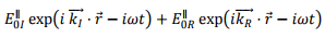
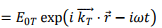
This equation must remain valid at all points in the interface and at all times. That is obviously possible if the exponential factors is the same for all the three terms or if they differe at best by a constant phase factor. Considering, the incident and the reflection terms, we have,
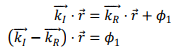
We are familiar with the vector equation to a plane and we know that if the position vector of a plane is and the normal to the plane is represented by  the equation to the plane is given by
  constant. Thus
  is normal to the interface plane. Since the interface is x-y plane, we take the plane containing the
  and
and  in the x-z plane.
Sinceand the normal to the plane is normal to the interface are in the same plane, we have,
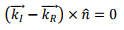
Thus we have, 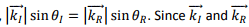 are in the same medium, though their directions are different, their magnitudes are the same
  and hence, we have,

which is the law of reflection.
We will now prove the Snell’s law.
Let us look into the equation
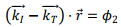
In a fashion similar to the above, we can show that
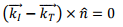
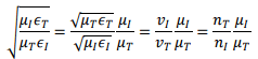
which gives 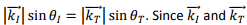 are in different media, we have, recognizing that as the wave goes from one medium to another, its frequency does not change,
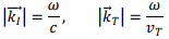
where  is the velocity of the wave in the transmitted medium. We, therefore, have,
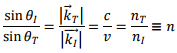
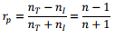
Here n is the refractive index of the second medium with respect to the incident medium.
Fresnel’s Equations
What happens to the amplitudes of the wave on reflection and transmission? Let us summarize the boundary conditions that we have derived in these lectures. We will assume that both the media are non-magnetic so that the permeability of both media are the same, viz., μ0. The two media differ by their dielectric constant, the incident medium is taken to be air as above. We further assume that there are no free charges or currents on the surface so that both the normal and tangential components of the fields are continuous. We will consider two cases, the first case where the electric fields are parallel to the incident plane. This case is known as p- polarization, p standing for “parallel”. The second case is where the electric field is perpendicular to the incident plane. This is referred to as s- polarization, s standing for a German word “senkrecht “ meaning perpendicular.
p- polarization
In this case, since the magnetic fields are perpendicular to the plane of incidence, we take the directions of the H fields to come out of the plane of the page (the incident plane). Since the electric field, the magnetic field and the direction of propagation are mutually perpendicular being a right handed triad, we have indicated the directions of the electric fields accordingly. It may be noted that in this picture, for the case of normal incidence, the incident and the reflected electric fields are directed oppositely. (The assumption is not restrictive because, if it is not true, a negative sign should appear in the equations ).
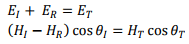
Taking the tangential components of the electric field (parallel to the interface), we have,
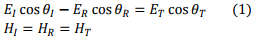
As our medium is linear, we have the following relationship between the electric and the magnetic field magnitudes,
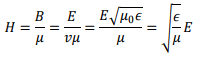
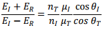
Thus the continuity of the tangential component of the magnetic field H can be expressed in terms of electric field amplitudes
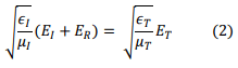
Equations (1) and (2) can be simplified (we use θR = θι)
where, nT and nI are refractive indices of the transmitted medium and incident medium, respectively, with respect to free space.
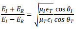
Thus, we have,
which gives,
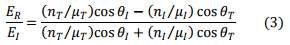
Substituting (3) in (2),
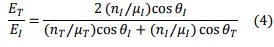
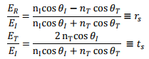
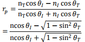
Let us take  The Fresnel’s equations are now expressible in terms of refractive indices of the two media and the angles of incidence and transmission

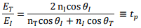
where,  and
and  are, respectively, the reflection and transmission coefficients for field amplitudes. (Caution : the phrases “reflection/transmission” coefficients are also used to denote fraction of transmitted intensities.)
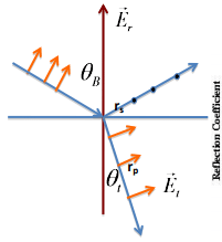
Brewster’s Angle
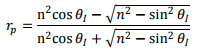
Using  we can express , as follows.
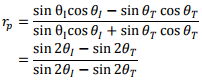
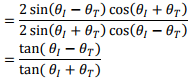
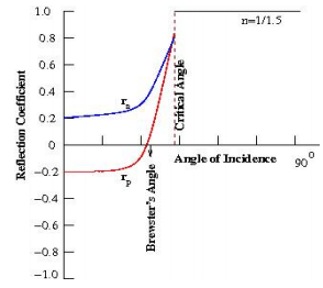
If  i.e. if the angle between the reflected ray and the transmitted ray is 900 , the reflection coefficient for the parallel polarization becomes zero, because
  If we had started with an equal mixture of p polarized and s polarized waves (i.e. an unpolarized wave), the reflected ray will have no p component, so that it will be plane polarized. The angle of incidence at which this happens is called the Brewster’s angle”.
For this angle, we have

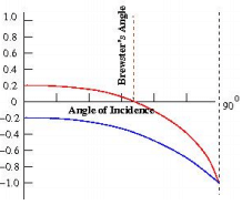
The following figure (right) , the red curve shows the variation in the reflected amplitude with the angle of incidence for p-polarization. The blue curve is the corresponding variation for s – polarization to be discussed below.
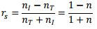
For normal incidence,  we have,
s –polarization
We next consider s polarization where the electric field is perpendicular to the incident plane. As we have taken the plane of incidence to be the plane of the paper, the electric field will be taken to come out of the plane of the paper.
The corresponding directions of the magnetic field is shown in the figure. The boundary conditions give
Substituting  we get for the reflection and transmission coefficient for the amplitudes of the electric field
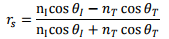
Using Snell’s law, we can simplify these expressions to get,
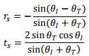
For normal incidence,  we have,
Notice that the expression differs from the expression forfor normal incidence, while both the results should have been the same. This is because of different conventions we took in fixing the directions in the two cases; in the p –polarization case, for normal incidence, the electric field directions are opposite for the incident and reflected rays while for the s-polarization, they have been taken to be along the same direction.
Total Internal Reflection and Evanescent Wave
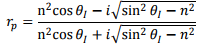
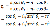
Let us return back to the case of p polarization and consider the case where in the incident medium has a higher refractive index than the transmitted medium. In this case, we can write the amplitude reflection coefficient as
where we have used the refractive index of the second medium as  Substituting Snell’s law into the above, we have,
  we can write the above as
The quantity under the square root could become negative for some values of  since n <1. we therefore write,
In a very similar way, we can show that the reflection coefficient for s polarization can be expressed as follows:
It may be seen that for  the magnitudes of bothand
  are both equal to unity because for both these, the numerator and the denominator are complex conjugate of each other. Thus it implies that when electromagnetic wave is incident at an angle of incidence greater than a “critical angle”defined by

where n here represents the refractive index of the (rarer) transmitted medium with respect to the(denser) incident medium , the wave is totally reflected. (In text books on optics, the critical angle is defined by the relation  because the refractive index there is conventionally defined as that of the denser medium with respect to the rarer one).
In case of total internal reflection, is there a wave in the transmitted medium? The answer is yes, it does as the following analysis shows.
Let us take the incident plane to be xz plane and the interface to be the xy plane so that the normal to the plane is along the z direction. The transmitted wave can be written as
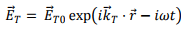
The space part of the wave can be expressed as
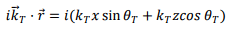
Writing this in terms of angle of incidence 
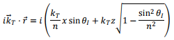
For angles greater than the critical angle the quantity within the square root is negative and we rewrite it as
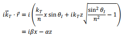
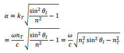
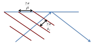
where, we define “propagation vector “ β as

and the “attenuation factor” α as
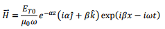
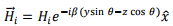
With this, the wave in the transmitted medium becomes,
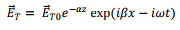
which shows that the wave in the second medium propagates along the interface. It penetrates into the medium but its amplitude attenuates exponentially. This is known as “evanescent wave”.
The amplitude variation with angle of incidence is shown in the following figure.
What is the propagation vector?
Recall that the magnitude of the propagation vector is defined as  where the “wavelength” λ is the distance between two successive crests or troughs of the wave measured along the direction of propagation. However, consider, for instance, a water wave which moves towards the shore. Along the shore, one would be more inclined to conclude that the wavelength is as measured by the distance between successive crests or troughs along the shore. This is the wavelength with which the attenuating surface wave propagates in the second medium.
No transfer of energy into the transmitted medium:
Though there is a wave in the transmitted medium, one can show that on an average, there is no transfer of energy into the medium from the incident medium.
Consider, p polarization, for which the transmitted electric field, being parallel to the incident (xz) plane is along the x direction.
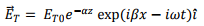
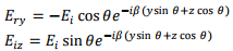
From this we obtain the H- field using Faraday’s law, Since the H field is taken perpendicular to the electric field , it would be in the y-z plane . Taking the components of  we have,
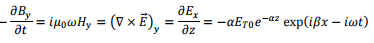
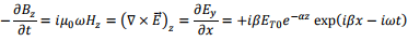
so that,
Thus the average energy transfer Poynting vector. The complex Poynting vector can be written as

so that the average power transferred into the second medium is
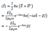
Since the normal to the surface is along the z direction, the average energy transferred to the second medium is zero.
Tutorial Assignment
- A plane electromagnetic wave described by its magnetic field is given by the expression
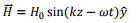 Determine the corresponding electric field and the time average Poynting vector.If it is incident normally on a perfect conductor and is totally reflected what would be the pressure exerted on the surface? Determine the surface current generated at the interface.
 - A circularly polarized electromagnetic wave is given by
 Show that the average value of the Poynting vector for the wave is equal to the sum of the Poynting vectors of its components.
Solutions to Tutorial Assignments
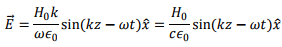
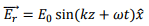
1. The wave is propagating along the + z direction (before reflection). The electric field is given by Maxwell- Ampere law,

Since  is along
  direction, and its y-component depends on z only, the curl is given by
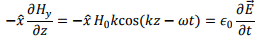
This gives,
The Poynting vector is given by
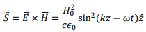
The time average Poynting vector is 
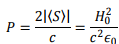
Since the wave is totally reflected, the change in momentum is twice the initial momentum carried. Thus the pressure is given by
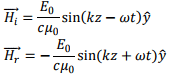
At the metallic interface (z=0), the tangential component of the electric field is zero. Since the wave is totally reflected, the reflected wave must have oppositely directed electric field, i.e. in  direction. The direction of propagation having been reversed, the magnetic the field is given by
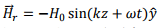
At the interface the total magnetic field is 
The surface current can be determined by taking an Amperian loop perpendicular to the interface, Taking the direction of the loop parallel to the magnetic field, the line integral is seen to be 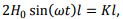 where K is the surface current density. The direction of the surface current is along the
  direction. Thus
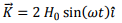
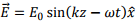
2. The electric field is given by 
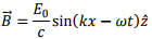
As the wave is propagating in the z direction, the corresponding magnetic field is given by
Poynting vector is
The individual components have average Poynting vectors given by
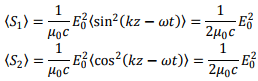
Thus 
Self Assessment Questions
1. The electric field of a plane electromagnetic wave propagating in free space is described by
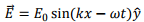
Determine the corresponding magnetic field and the time average Poynting vector for the wave.
2. Show that an s –polarized wave cannot be totally transmitted to another medium.
3. An electromagnetic wave given by
is incident on the surface of a perfect conductor and is totally reflected. The incident and the reflected waves combine and form a pattern. What is the average Poynting vector?
Solutions to Self Assessment Questions
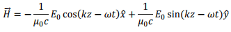
1. The wave is propagating in +x direction so that the propagation vector is  Using Faraday’s law, we have,
  which gives magnetic field directed along the z direction,
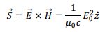
The Poynting vector is given by
The time average of the Poynting vector is 
2. Considering Fresnel equations for s polarization,
For total transmission  so that
 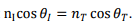 From Snell’s law, we have,
 Squaring and adding, we get
  which is not correct.
3. The incident wave is
Since the tangential component of the electric field must vanish at the interface (z=0), the reflected wave us given by
The corresponding magnetic fields are given by
The individual Poynting vectors can be calculated and on adding it will turn out that the average Poynting vector is zero. The waves of the type obtained by superposition of the two waves have the structure,
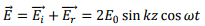
where the space and time parts are separated. These are known as “standing waves” and they do not transport energy.
Propagation of Electromagnetic Waves in a Conducting Medium
We will consider a plane electromagnetic wave travelling in a linear dielectric medium such as air along the z direction and being incident at a conducting interface. The medium will be taken to be a linear medium. So that one can describe the electrodynamics using only the E and H vectors. We wish to investigate the propagation of the wave in the conducting medium.
As the medium is linear and the propagation takes place in the infinite medium, the vectors  and
and  are still mutually perpendicular. We take the electric field along the x direction, the magnetic field along the y- dirrection and the propagation to take place in the z direction. Further, we will take the conductivity to be finite and the conductor to obey Ohm’s law,
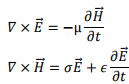
  Consider the pair of curl equations of Maxwell.
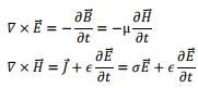
Let us take  to be respectively in x, y and z direction. We the nhave,
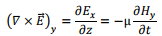
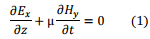
i.e.,
and
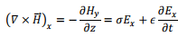
i.e.
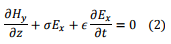
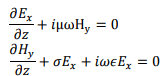
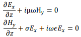
We take the time variation to be harmonic  so that the time derivative is equivalent to a multiplication by
  . The pair of equations (1) and (2) can then be written as
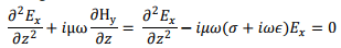
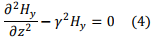
We can solve this pair of coupled equations by taking a derivative of either of the equations with respect to z and substituting the other into it,
Define, a complex constan γ through
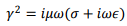
in terms of which we have,
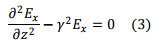
In an identical fashion, we get
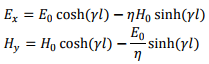
Solutions of (3) and (4) are well known and are expressed in terms of hyperbolic functions,
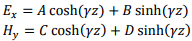
where A, B, C and D are constants to be determined. If the values of the electric field at z=0 is E0 and that of the magnetic field at z=0 is H0 we have A E0 and C =H0.
In order to determine the constants B and D, let us return back to the original first order equations (1) and (2)
Substituting the solutions for E and H

This equation must remain valid for all values of z, which is possible if the coefficients of sinh and cosh terms are separately equated to zero,
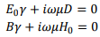
The former gives,
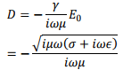
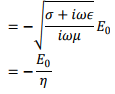
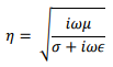
where
Likewise, we get,

Substituting these, our solutions for the E and H become,
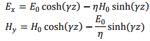
The wave is propagating in the z direction. Let us evaluate the fields when the wave has reached 
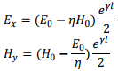
If ℓ is large, we can approximate
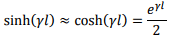
we then have,
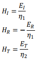
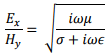
The ratio of the magnitudes of the electric field to magnetic field is defined as the “characteristic impedance” of the wave
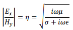
Suppose we have lossless medium, σ=0, i.e. for a perfect conductor, the characteristic impedance is

If the medium is vacuum,  gives η≈377Ω. The characteristic impedance, as the name suggests, has the dimension of resistance.
In this case, 
Let us look at the full three dimensional version of the propagation in a conductor. Once again, we start with the two curl equations,
Take a curl of both sides of the first equation,
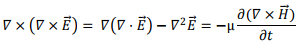
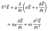
As there are no charges or currents, we ignore the divergence term and substitute for the curl of H from the second equation,
We take the propagating solutions to be
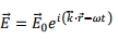
so that the above equation becomes,
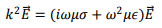
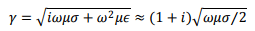
so that we have, the complex propagation constant to be given by
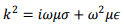
so that
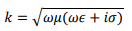
k is complex and its real and imaginary parts can be separated by standard algebra,
we have
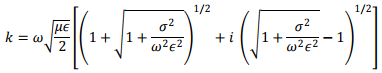
Thus the propagation vector β and the attenuation factor α are given by
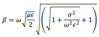
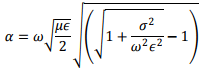
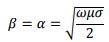
The ration  determines whether a material is a good conductor or otherwise. Consider a good conductor for which σ>> ω∈.For this case, we have,
The speed of electromagnetic wave is given by

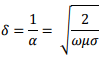
The electric field amplitude diminishes with distance as  The distance to which the field penetrates before its amplitude diminishes be a factor e-1 is known as the “skin depth” , which is given by
The wave does not penetrate much inside a conductor. Consider electromagnetic wave of frequency 1 MHz for copper which has a conductivity of approximately  Substituting these values, one gets the skin depth in Cu to be about 0.067 mm. For comparison, the skin depth in sea water which is conducting because of salinity, is about 25 cm while that for fresh water is nearly 7m. Because of small skin depth in conductors, any current that arises in the metal because of the electromagnetic wave is confined within a thin layer of the surface.
Reflection and Transmission from interface of a conductor
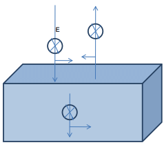
Consider an electromagnetic wave to be incident normally at the interface between a dielectric and a conductor. As before, we take the media to be linear and assume no charge or current densities to exist anywhere. We then have a continuity of the electric and the magnetic fields at the interface so that

The relationships between the magnetic field and the electric field are given by
the minus sign in the second relation comes because of the propagation direction having been reversed on reflection.
Solving these, we get,
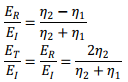
The magnetic field expressions are given by interchanging η1 and η2 in the above expressions.
Let us look at consequence of this. Consider a good conductor such as copper. We can see that η2 is a small complex number. For instance, taking the wave frequency to be 1 MHz and substituting conductivity of Cu to be  we can calculate η2 to be approximately
 whereas the vacuum impedance η1= 377 Ω. This implies
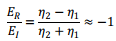
which shows that a good metal is also a good reflector. On the other hand, if we calculate the transmission coefficient we find it to be substantially reduced, being only about 
For the transmitted magnetic field, the ratio  is approximately +2. Though E is reflected with a change of phase, the magnetic field is reversed in direction but does not undergo a phase change. The continuity of the magnetic field then requires that the transmitted field be twice as large.
Surface Impedance
As we have seen, the electric field is confined to a small depth at the conductor interface known as the skin depth. We define surface impedance as the ratio of the parallel component of electric field that gives rise to a current at the conductor surface,

where ks is the surface current density.
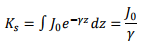
Assuming that the current flows over the skin depth, one can write, for the current density, (assuming no reflection from the back of this depth)

Since the current density has been taken to decay exponentially, we can extend the integration to infinity and get
The current density at the surface can be written as  For a good conductor, we have,
Thus
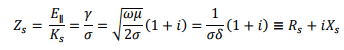
where the surface resistance Rs and surface reactance Xs are given by

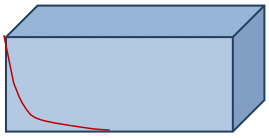
The current profile at the interface is as shown.
Tutorial Assignment
- A 2 GHz electromagnetic propagates in a non-magnetic medium having a relative permittivity of 20 and a conductivity of 3.85 S/m. Determine if the material is a good conductor or otherwise. Calculate the phase velocity of the wave, the propagation and attenuation constants, the skin depth and the intrinsic impedance.
- An electromagnetic wave with its electric field parallel to the plane of incidence is incident from vacuum onto the surface of a perfect conductor at an angle of incidence θ. Obtain an expression for the total electric and the magnetic field.
Solutions to Tutorial Assignments
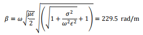
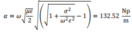
1. One can see that  The ratio of conductivity σ ω∈ is 1.73 which says it is neither a good metal nor a good dielectric. The propagation constant β and the attenuation constant α are given by,
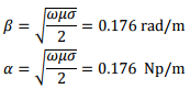
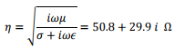
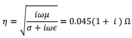
The intrinsic impedance is
The phase velocity is 
The skin depth is 
2. The case of p polarization is shown.
Let the incident plane be y-z plane. Let us look at the magnetic field. We have, since both the incident and the reflected fields are in the same medium,

Let us write the incident magnetic field as
The reflected magnetic field is given by
Since the tangential components of the electric field is continuous, we have,
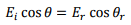
As  we have
  and consequently,
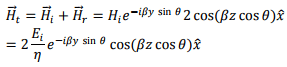
  Thus the total magnetic field can be written as
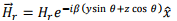
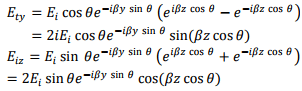
The electric field has both y and z components,
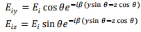
The reflected electric field also has both components,
Adding these two the total electric field, has the following components,
Self Assessment Questions
- For electromagnetic wave propagation inside a good conductor, show that the electric and the magnetic fields are out of phase by 450 .
- A 2 kHz electromagnetic propagates in a non-magnetic medium having a relative permittivity of 20 and a conductivity of 3.85 S/m. Determine if the material is a good conductor or otherwise. Calculate the phase velocity of the wave, the propagation and attenuation constants, the skin depth and the intrinsic impedance.
- An electromagnetic wave with its electric field perpendicular to the plane of incidence is incident from vacuum onto the surface of a perfect conductor at an angle of incidence θ. Obtain an expression for the total electric and the magnetic field.
Solutions to Self Assessment Questions
1. From the text, we see that the ratio of electric field to magnetic field is given by
For a good conductor, we can approximate this by 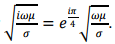
2. One can see that  The ratio of conductivity
 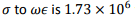 which says it is r a good metal. The propagation constant β and the attenuation constant α are given by,
The intrinsic impedance is
The phase velocity is 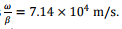
The skin depth is 
3. The direction of electric and magnetic field for s polarization is as shown below.
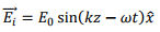
Let the incident plane be y-z plane. The incident electric field is
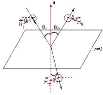
taken along the x direction and is given by
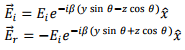
The minus sign comes because at z=0, for any y, the tangential component of the electric field must be zero.
The total electric field is along the x direction and is given by the sum of the above,
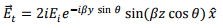
which is a travelling wave in the y direction but a standing wave in the z direction. Since the wave propagates in vacuum, we have,

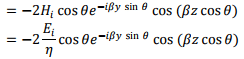
The magnetic field has both y and z components.


|
27 videos|333 docs
|
FAQs on Electromagnetic Waves - GATE Notes & Videos for Electrical Engineering - Electrical Engineering (EE)
| 1. What are electromagnetic waves? |  |
| 2. How do electromagnetic waves propagate? | |
| 3. What are the different types of electromagnetic waves? | |
| 4. How do electromagnetic waves interact with matter? | |
| 5. What are the practical applications of electromagnetic waves? | |


Free
,past year papers
,video lectures
,ppt
,Electromagnetic Waves | GATE Notes & Videos for Electrical Engineering - Electrical Engineering (EE)
,Electromagnetic Waves | GATE Notes & Videos for Electrical Engineering - Electrical Engineering (EE)
,mock tests for examination
,Previous Year Questions with Solutions
,Sample Paper
,practice quizzes
,Exam
,Important questions
,Semester Notes
,Summary
,Extra Questions
,study material
,shortcuts and tricks
,Viva Questions
,MCQs
,Electromagnetic Waves | GATE Notes & Videos for Electrical Engineering - Electrical Engineering (EE)
,Objective type Questions
;


Electromagnetic Waves Free PDF Download
Importance of Electromagnetic Waves
Electromagnetic Waves Notes
Electromagnetic Waves Electrical Engineering (EE) Questions
Study Electromagnetic Waves on the App
|
© EduRev
|
Education Revolution
|


|


