Flanged Beams: Theory - Civil Engineering (CE) PDF Download

Instructional Objectives: At the end of this lesson, the student should be able to:
- identify the regions where the beam shall be designed as a flanged and where it will be rectangular in normal slab beam construction,
- define the effective and actual widths of flanged beams,
- state the requirements so that the slab part is effectively coupled with the flanged beam,
- write the expressions of effective widths of T and L-beams both for continuous and isolated cases,
- derive the expressions of C, T and Mu for four different cases depending on the location of the neutral axis and depth of the flange.
5.10.1 Introduction


Reinforced concrete slabs used in floors, roofs and decks are mostly cast monolithic from the bottom of the beam to the top of the slab. Such rectangular beams having slab on top are different from others having either no slab (bracings of elevated tanks, lintels etc.) or having disconnected slabs as in some pre-cast systems (Figs. 5.10.1 a, b and c). Due to monolithic casting, beams and a part of the slab act together. Under the action of positive bending moment, i.e., between the supports of a continuous beam, the slab, up to a certain width greater than the width of the beam, forms the top part of the beam. Such beams having slab on top of the rectangular rib are designated as the flanged beams - either T or L type depending on whether the slab is on both sides or on one side of the beam (Figs. 5.10.2 a to e). Over the supports of a continuous beam, the bending moment is negative and the slab, therefore, is in tension while a part of the rectangular beam (rib) is in compression. The continuous beam at support is thus equivalent to a rectangular beam (Figs. 5.10.2 a, c, f and g).

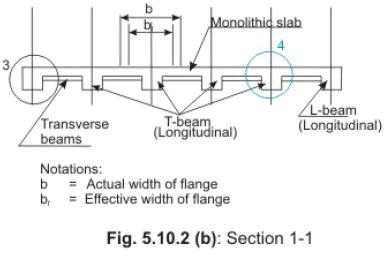


The actual width of the flange is the spacing of the beam, which is the same as the distance between the middle points of the adjacent spans of the slab, as shown in Fig. 5.10.2 b. However, in a flanged beam, a part of the width less than the actual width, is effective to be considered as a part of the beam. This width of the slab is designated as the effective width of the flange.
5.10.2 Effective Width


5.10.2.1 IS code requirements
The following requirements (cl. 23.1.1 of IS 456) are to be satisfied to ensure the combined action of the part of the slab and the rib (rectangular part of the beam).
(a) The slab and the rectangular beam shall be cast integrally or they shall be effectively bonded in any other manner.
(b) Slabs must be provided with the transverse reinforcement of at least 60 per cent of the main reinforcement at the mid span of the slab if the main reinforcement of the slab is parallel to the transverse beam (Figs. 5.10.3 a and b).


The variation of compressive stress (Fig. 5.10.4) along the actual width of the flange shows that the compressive stress is more in the flange just above the rib than the same at some distance away from it. The nature of variation is complex and, therefore, the concept of effective width has been introduced. The effective width is a convenient hypothetical width of the flange over which the compressive stress is assumed to be uniform to give the same compressive force as it would have been in case of the actual width with the true variation of compressive stress.
5.10.2.2 IS code specifications
Clause 23.1.2 of IS 456 specifies the following effective widths of T and L-beams:
(a) For T-beams, the lesser of
(i) bf = lo/6 + bw + 6 Df
(ii) bf = A ctual width of the flange
(b) For isolated T-beams, the lesser of

(ii) bf = A ctual width of the flange
(c) For L-beams, the lesser of
(i) bf = lo/12 + bw + 3 Df
(ii) bf = A ctual width of the flange
(d) For isolated L-beams, the lesser of

(ii) bf = A ctual width of the flange
where bf = effective width of the flange,
lo = distance between points of zero moments in the beam, which is the effective span for simply supported beams and 0.7 times the effective span for continuous beams and frames,
bw = beadth of the web,
Df = thickness of the flange, and
b = actual width of the flange.
5.10.3 Four Different Cases
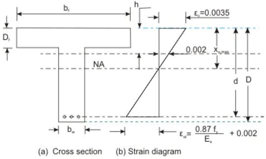
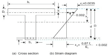
The neutral axis of a flanged beam may be either in the flange or in the web depending on the physical dimensions of the effective width of flange bf, effective width of web bw, thickness of flange Df and effective depth of flanged beam d (Fig. 5.10.4). The flanged beam may be considered as a rectangular beam of width bf and effective depth d if the neutral axis is in the flange as the concrete in tension is ignored. However, if the neutral axis is in the web, the compression is taken by the flange and a part of the web.


All the assumptions made in sec. 3.4.2 of Lesson 4 are also applicable for the flanged beams. As explained in Lesson 4, the compressive stress remains constant between the strains of 0.002 and 0.0035. It is important to find the depth h of the beam where the strain is 0.002 (Fig. 5.10.5 b). If it is located in the web, the whole of flange will be under the constant stress level of 0.446 fck. The following gives the relation of Df and d to facilitate the determination of the depth h where the strain will be 0.002. From the strain diagram of Fig. 5.10.5 b:

or  (5.1)
(5.1)
when xu = xu, max , we get
h=  = 0.227d , 0.205d and 0.197 7d , for Fe 250, Fe 415 and Fe 500, respectively. In general, we can adopt, say
h/d = 0.2 (5.2)
The same relation is obtained below from the values of strains of concrete and steel of Fig. 5.10.5 b.

or (5.3)
(5.3)
Dividing Eq. 5.1 by Eq. 5.3
 (5.4)
(5.4)
Using  + 0.002 in Eq. 5.4, we get h/d = 0.227, 0.205 and 0.197 for Fe 250, Fe 415 and Fe 500 respectively, and we can adopt h/d = 0.2 (as in Eq. 5.2).
Thus, we get the same Eq. 5.2 from Eq. 5.4, h/d = 0.2 (5.2)
It is now clear that the three values of h are around 0.2 d for the three grades of steel. The maximum value of h may be Df, at the bottom of the flange where the strain will be 0.002, if Df /d = 0.2. This reveals that the thickness of the flange may be considered small if Df /d does not exceed 0.2 and in that case, the position of the fibre of 0.002 strain will be in the web and the entire flange will be under a constant compressive stress of 0.446 fck .
On the other hand, if Df is > 0.2 d, the position of the fibre of 0.002 strain will be in the flange. In that case, a part of the slab will have the constant stress of 0.446 fck where the strain will be more than 0.002.
Thus, in the balanced and over-reinforced flanged beams (when xu = xu , max ), the ratio of Df /d is important to determine if the rectangular stress block is for the full depth of the flange (when Df /d does not exceed 0.2) of for a part of the flange (when Df /d > 0.2). Similarly, for the under-reinforced flanged beams, the ratio of Df /xu is considered in place of Df /d. If Df /xu does not exceed 0.43 (see Eq. 5.1), the constant stress block is for the full depth of the flange. If Df /xu > 0.43, the constant stress block is for a part of the depth of the flange. Based on the above discussion, the four cases of flanged beams are as follows:


(i) Neutral axis is in the flange (xu < Df ), (Fig. 5.10.6 a to c)

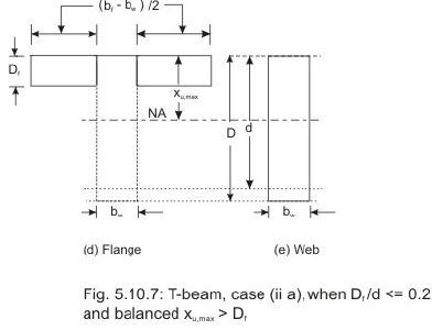


(ii) Neutral axis is in the web and the section is balanced (xu = xu,max > Df), (Figs. 5.10.7 and 8 a to e)
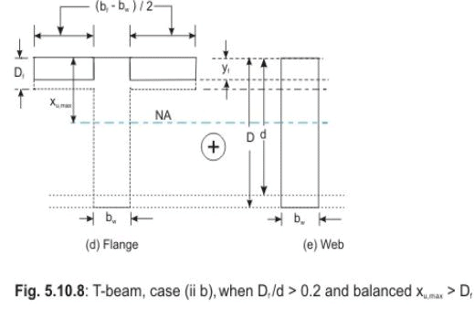
It has two situations: (a) when Df /d does not exceed 0.2, the constant stress block is for the entire depth of the flange (Fig. 5.10.7), and (b) when Df /d > 0.2, the constant stress block is for a part of the depth of flange (Fig. 5.10.8).
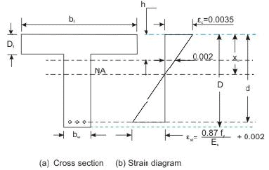


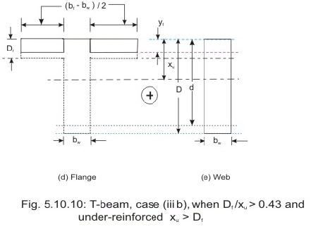
(iii) Neutral axis is in the web and the section is under-reinforced (xu,max > xu > Df), (Figs. 5.10.9 and 10 a to e)
This has two situations: (a) when Df /xu does not exceed 0.43, the full depth of flange is having the constant stress (Fig. 5.10.9), and (b) when Df /xu > 0.43, the constant stress is for a part of the depth of flange (Fig. 5.10.10).
(iv) Neutral axis is in the web and the section is over-reinforced (xu > xu,max> Df), (Figs. 5.10.7 and 8 a to e)
As mentioned earlier, the value of xu is then taken as xu,max when xu> xu,max. Therefore, this case also will have two situations depending on Df /d not exceeding 0.2 or > 0.2 as in (ii) above.
The governing equations of the four different cases are now taken up.
5.10.4 Governing Equations
The following equations are only for the singly reinforced T-beams. Additional terms involving Mu,lim, Mu2, Asc , Ast1 and Ast2 are to be included from Eqs. 4.1 to 4.8 of sec. 4.8.3 of Lesson 8 depending on the particular case. Applications of these terms are explained through the solutions of numerical problems of doubly reinforced T-beams in Lessons 11 and 12.
5.10.4.1 Case (i): When the neutral axis is in the flange (xu < Df ), (Figs. 5.10.6 a to c)
Concrete below the neutral axis is in tension and is ignored. The steel reinforcement takes the tensile force (Fig. 5.10.6). Therefore, T and L-beams are considered as rectangular beams of width bf and effective depth d. All the equations of singly and doubly reinforced rectangular beams derived in Lessons 4 to 5 and 8 respectively, are also applicable here.
5.10.4.2 Case (ii): When the neutral axis is in the web and the section is balanced (xu,max > Df ), (Figs. 5.10.7 and 8 a to e)
(a) When Df /d does not exceed 0.2, (Figs. 5.10.7 a to e)
As explained in sec. 5.10.3, the depth of the rectangular portion of the stress block (of constant stress = 0.446 fck) in this case is greater than Df (Figs. 5.10.7 a, b and c). The section is split into two parts: (i) rectangular web of width bw and effective depth d, and (ii) flange of width (bf - bw) and depth Df (Figs. 5.10.7 d and e).
Total compressive force = Compressive force of rectangular beam of width bw and depth d + Compressive force of rectangular flange of width (bf - bw) and depth Df . Thus, total compressive force
C = 0.36 fck bw xu, max + 0.45 fck (bf - bw) Df (5.5)
(Assuming the constant stress of concrete in the flange as 0.45 fck in place of 0.446 fck ,as per G-2.2 of IS 456), and the tensile force T = 0.87 fy Ast (5.6)
The lever arm of the rectangular beam (web part) is (d - 0.42 xu, max) and the same for the flanged part is (d - 0.5 Df ).
So, the total moment = Moment due to rectangular web part + Moment due to rectangular flange part
or Mu = 0.36 fck bw xu, max (d - 0.42 xu, max ) + 0.45 fck (bf - bw) Df (d - Df /2)
or Mu = 0.36(xu, max /d){1 - 0.42( xu, max/d)} fck bw d2 + 0.45 fck(bf - bw) Df(d - Df /2) (5.7)
Equation 5.7 is given in G-2.2 of IS 456.
(b) When Df /d > 0.2, (Figs. 5.10.8 a to e)
In this case, the depth of rectangular portion of stress block is within the flange (Figs. 5.10.8 a, b and c).
It is assumed that this depth of constant stress (0.45 fck) is yf, where yf = 0.15 xu, max + 0.65 Df, but not greater than Df (5.8)
The above expression of yf is derived in sec. 5.10.4.5. As in the previous case (ii a), when Df /d does not exceed 0.2, equations of C, T and Mu are obtained from
Eqs. 5.5, 6 and 7 by changing Df to yf. Thus, we have (Figs. 5.10.8 d and e) C = 0.36 fck bw xu, max + 0.45 fck (bf - bw) yf (5.9)
T = 0.87 fy Ast (5.10)
The lever arm of the rectangular beam (web part) is (d - 0.42 xu, max ) and the same for the flange part is (d - 0.5 yf ). Accordingly, the expression of Mu is as follows:
Mu = 0.36(xu, max /d){1 - 0.42( xu, max/d)} fck bw d2 + 0.45 fck(bf - bw) yf(d - yf /2) (5.11)
5.10.4.3 Case (iii): When the neutral axis is in the web and the section is under-reinforced (xu > Df ), (Figs. 5.10.9 and 10 a to e)
(a) When Df / xu does not exceed 0.43, (Figs. 5.10.9 a to e)
Since Df doe s not exceed 0.43 xu and h (depth of fibre where the strain is 0.002) is at a depth of 0.43 xu, the entire flange will be under a constant stress of 0.45 fck (Figs. 5.10.9 a, b and c). The equations of C, T and Mu can be written in the same manner as in sec. 5.10.4.2, case (ii a). The final forms of the equations are obtained from Eqs. 5.5, 6 and 7 by replacing xu, max by xu. Thus, we have (Figs. 5.10.9 d and e) C = 0.36 fck bw xu + 0.45 fck (bf - bw) Df (5.12)
T = 0.87 fy Ast (5.13)
Mu = 0.36(xu /d){1 - 0.42( xu /d)} fck bw d2 + 0.45 fck(bf - bw) Df (d - Df /2) (5.14)
(b) When Df / xu > 0.43, (Figs. 5.10.10 a to e)
Since Df > 0.43 xu and h (depth of fibre where the strain is 0.002) is at a depth of 0.43 xu, the part of the flange having the constant stress of 0.45 fck is assumed as yf (Fig. 5.10.10 a, b and c). The expressions of yf , C, T and Mu can be written from Eqs. 5.8, 9, 10 and 11 of sec. 5.10.4.2, case (ii b), by replacing xu,max by xu. Thus, we have (Fig. 5.10.10 d and e) yf = 0.15 xu + 0.65 Df, but not greater than Df (5.15)
C = 0.36 fck bw xu + 0.45 fck (bf - bw) yf (5.16)
T = 0.87 fy Ast (5.17)
Mu = 0.36(xu /d){1 - 0.42( xu /d)} fck bw d2 + 0.45 fck(bf - bw) yf (d - yf /2) (5.18)
5.10.4.4 Case (iv): When the neutral axis is in the web and the section is over-reinforced (xu > Df ), (Figs. 5.10.7 and 8 a to e)
For the over-reinforced beam, the depth of neutral axis xu is more than xu, max as in rectangular beams. However, xu is restricted up to xu,max. Therefore, the corresponding expressions of C, T and Mu for the two situations (a) when Df / d does not exceed 0.2 and (b) when Df / d > 0.2 are written from Eqs. 5.5 to 5.7 and 5.9 to 5.11, respectively of sec. 5.10.4.2 (Figs. 5.10.7 and 8). The expression of yf for (b) is the same as that of Eq. 5.8.
(a) When Df /d does not exceed 0.2 (Figs. 5.10.7 a to e)
The equations are: C = 0.36 fck bw xu, max + 0.45 fck (bf - bw) Df (5.5) T = 0.87 fy Ast (5.6)
Mu = 0.36(xu, max /d){1 - 0.42( xu, max/d)} fck bw d2 + 0.45 fck(bf - bw) Df(d - Df /2) (5.7)
(b) When Df /d > 0.2 (Figs. 5.10.8 a to e)
yf = 0.15 xu, max + 0.65 Df, but not greater than Df (5.8)
C = 0.36 fck bw xu, max + 0.45 fck (bf - bw) yf (5.9) T = 0.87 fy Ast (5.10)
Mu = 0.36(xu, max /d){1 - 0.42( xu, max/d)} fck bw d2 + 0.45 fck(bf - bw) yf(d - yf /2) (5.11)
It is clear from the above that the over-reinforced beam will not have additional moment of resistance beyond that of the balanced one. Moreover, it will prevent steel failure. It is, therefore, recommended either to re-design or to go for doubly reinforced flanged beam than designing over-reinforced flanged beam.
5.10.4.5 Derivation of the equation to determine yf , Eq. 5.8, Fig. 5.10.11

Whitney's stress block has been considered to derive Eq. 5.8. Figure 5.10.11 shows the two stress blocks of IS code and of Whitney. yf = Depth of constant portion of the stress block when Df /d > 0.2. As yf is a function of xu and Df and let us assume yf = A xu + B Df (5.19)
where A and B are to be determined from the following two conditions: (i) yf = 0.43 xu , when Df = 0.43 xu (5.20)
(ii) yf = 0.8 xu , when Df = xu (5.21)
Using the conditions of Eqs. 5.20 and 21 in Eq. 5.19, we get A = 0.15 and B = 0.65. Thus, we have yf = 0.15 xu + 0.65 Df (5.8)
Summary of this Lesson
This lesson illustrates the practical situations when slabs are cast integrally with the beams to form either T and L-beams or rectangular beams. The concept of effective width of the slab to form a part of the beam has been explained. The requirements as per IS 456 have been illustrated so that the considered part of the slab may become effective as a beam. Expressions of effective widths for different cases of T and L-beams are given. Four sets of governing equations for determining C, T and Mu are derived for four different cases. These equations form the basis of analysis and design of singly and doubly reinforced T and L- beams.
FAQs on Flanged Beams: Theory - Civil Engineering (CE)
| 1. What is a flanged beam in civil engineering? |  |
| 2. How are flanged beams different from other types of beams in civil engineering? | |
| 3. What are the advantages of using flanged beams in civil engineering projects? | |
| 4. How are flanged beams designed and analyzed in civil engineering? | |
| 5. What are some common applications of flanged beams in civil engineering? | |


Extra Questions
,ppt
,video lectures
,Summary
,practice quizzes
,past year papers
,Previous Year Questions with Solutions
,Semester Notes
,Free
,mock tests for examination
,Exam
,Viva Questions
,MCQs
,Important questions
,Objective type Questions
,Flanged Beams: Theory - Civil Engineering (CE)
,shortcuts and tricks
,Sample Paper
,Flanged Beams: Theory - Civil Engineering (CE)
,study material
,Flanged Beams: Theory - Civil Engineering (CE)
;


Flanged Beams: Theory Free PDF Download
Importance of Flanged Beams: Theory
Flanged Beams: Theory Notes
Flanged Beams: Theory Civil Engineering (CE) Questions
Study Flanged Beams: Theory on the App
|
© EduRev
|
Education Revolution
|


|


