Types & Uses: Riveted Joints

1. Rivets as permanent joints:
Often small machine components are joined together to form a larger machine part. The design of joints is as important as that of individual machine components because a weak joint may spoil the utility of a carefully designed machine part.
Mechanical joints are broadly classified into two categories: non-permanent joints and permanent joints.
- Non-permanent joints can be assembled and disassembled without damaging the components. Examples are threaded fasteners (screws, bolts and nuts), keys and couplings.
- Permanent joints cannot be disassembled without damaging the components. These are of two kinds depending upon the nature of the force that holds the parts together:
- Joints held by mechanical force - for example, riveted joints and joints produced by press or interference fits.
- Joints held by molecular or metallurgical forces - for example, welded joints, brazed joints and adhesive joints.
Until comparatively recently, riveted joints were widely used to join structural members. Improvements in welding and high-strength bolted fastenings have reduced the use of rivets. Nevertheless, rivets remain important in applications such as ship hulls, bridges, boilers, tanks and shells where a durable, leak-resistant permanent joint is required.
2. Rivets and Riveting:
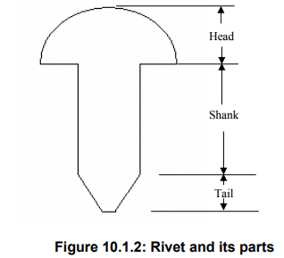
A rivet is a short cylindrical rod having a manufactured head at one end and a tail that is upset to form a second head during assembly. The main cylindrical portion of the rivet is called the shank.
Rivet head forms and dimensions for general purposes are given by Indian Standards: IS: 2155-1982 (for rivet diameters below 12 mm) and IS: 1929-1982 (for diameters from 12 mm to 48 mm). Rivet heads for boiler work are covered by IS: 1928-1978. Standard handbooks and machine design references give the detailed head dimensions for practical use.
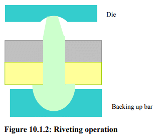
Riveting is the operation of joining two or more plates by using rivets. Smooth holes are drilled (or punched and reamed) in the plates to be joined and a rivet is inserted through the aligned holes. The rivet is then deformed at the tail end by applying adequate mechanical force while the head is backed up on the opposite side. The tail is upset plastically to form a second head, producing a close, pressure bearing fit between rivet head, plates and formed tail.
The riveting process may be of two types:
- Cold riveting - the riveting is done at ambient temperature, using purely mechanical upsetting.
- Hot riveting - the rivet is heated before insertion and upsetting; the hot rivet is then upset and usually cooled in place. Hot riveting was traditionally used for thicker sections or for achieving a closer fit.
After upsetting, if a leak-tight joint is required, an additional operation called caulking is often performed; caulking slightly displaces metal around the hole to seal gaps. A backing-up bar or bucking bar is commonly used to support the head while the tail is formed (see figure references in standard texts).
Types of riveted joints and joint efficiency:
Riveted joints are mainly of two types:
- Lap joints
- Butt joints
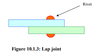
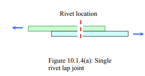
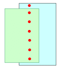
Lap joints
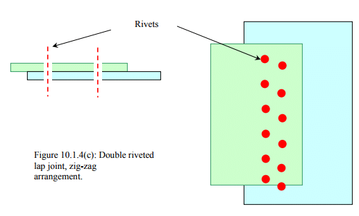
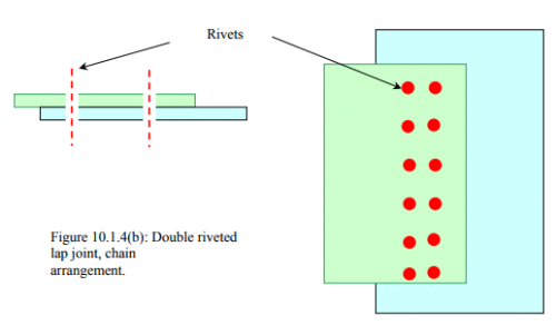
In a lap joint the plates to be joined overlap and rivets are placed through the overlapping portion. A single row or multiple rows of rivets can be used depending on the required strength. Multiple rows may be arranged as chain riveting (adjacent rows having rivets in the same transverse line) or zig-zag riveting (adjacent rows staggered or offset).
Common forms of lap joints include single-riveted, double-riveted and triple-riveted lap joints. Different practical arrangements are illustrated in standard figures used in machine design.
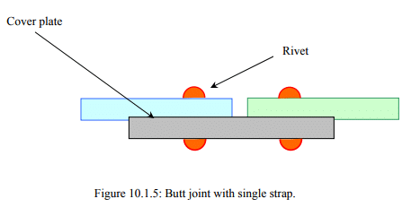
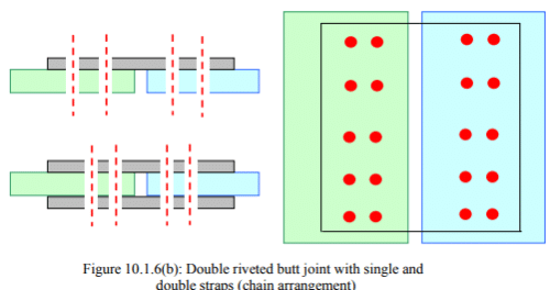
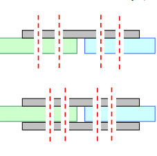
Butt joints
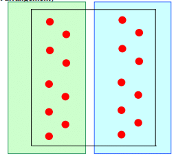
In a butt joint the plate ends meet without overlap. Rivets are used to attach one or two cover plates (also called straps) to the abutting ends. Depending on the number of cover plates, butt joints are classed as single-strap or double-strap butt joints. The rivet arrangements may be single row, double row, chain or zig-zag, and may include one or more rows through each cover plate.
A single-strap butt joint, and several alternative arrangements, are commonly used in boiler and structural work where a flush joint is required.
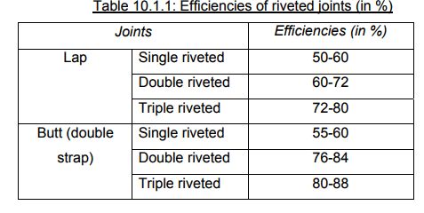

The efficiency of a riveted joint is defined as the ratio of the strength of the riveted joint to the strength of the corresponding solid (un-riveted) plate, usually expressed as a percentage. Efficiency depends on rivet size and strength, plate thickness and material strength, the arrangement of rivets (single or multiple rows, chain or zig-zag), spacing and edge distance. Typical efficiency values for commercial boiler joints are available in standard tables and depend on joint type and workmanship.
Important terms used in riveted joints
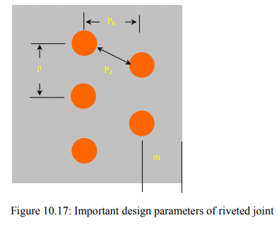
Several geometric parameters are used to describe the arrangement of rivets in a joint. Common parameters are:
- Pitch (p): the centre-to-centre distance between consecutive rivets in a single row.
- Back pitch (pt or pb): the shortest distance between centres of two successive rows in a multiple-row joint.
- Diagonal pitch (pd): the centre-to-centre distance between rivets in adjacent rows for a zig-zag riveted joint.
- Margin or edge distance (m): the distance from the centre of a rivet hole to the nearest free edge of the plate.
Design considerations, strength modes and recommended dimensions
When designing riveted joints the following failure modes and strengths must be compared to determine the governing limit state:
- Shear failure of rivet - the rivet may fail in single or multiple shear planes depending on the joint arrangement.
- Bearing failure (compressive bearing) of the plate - the plate material around the rivet hole may yield in bearing.
- Tear-out or net-section failure of the plate - the plate may fail in tension across the net area left after holes are cut.
- Failure of the strap or cover plate - in butt joints the cover plate may determine the strength.
Representative formulae used in preliminary design (symbols defined in the text) are:
Shear strength of a single rivet in single shear:
Pshear = τ × A = τ × (π d² / 4)
Bearing strength of plate at a rivet (approximate):
Pbearing = σb × d × t
Tensile strength of an uncut plate of width w and thickness t:
Pplate = σt × w × t
Tensile strength of plate with rivet holes (net section) for n holes across the section:
Pnet = σt × (w - n d) × t
Design practice therefore compares rivet shear capacity, bearing capacity of the plate and net-section capacity of the plate. The smallest of these values controls the design. Allowable stresses (τ, σb, σt) are chosen from material properties with suitable safety factors.
Recommended practical guidelines used in design:
- Minimum pitch p is typically taken as ≥ 3 d (three times rivet diameter) to avoid tearing between rivets and to ensure adequate distribution of stresses.
- Minimum margin (edge distance) m is typically taken as ≥ 1.5 d to prevent edge tear-out under tensile loading.
- Hole diameter is usually taken slightly greater than the rivet shank diameter to allow assembly; allowance depends on hot or cold riveting and standard practice.
- When multiple shear planes exist (e.g., double shear), the rivet shear area and capacity increase proportionately.
Practical considerations, inspection and applications
Practical aspects in rivet design and fabrication include selection of rivet material and size, proper hole preparation (drilling and reaming rather than rough punching for high quality joints), correct rivet heating (for hot riveting), correct upsetting to form a well-filled tail head, and caulking where leak-tightness is required.
Inspection of riveted joints includes checking head formation, absence of cracks in rivet heads or plates, uniform tightness and absence of corrosion. Good workmanship is essential for the expected joint efficiency to be achieved.
Typical applications of riveted joints are:
- Ship hull plates and bulkheads
- Bridge and structural members (historical and certain repair situations)
- Boilers, pressure vessels and tanks where a reliable, permanent joint is required
- Aircraft in early construction; modern practice uses high-strength fasteners or welding/composite-bonding depending on design requirements
Summary: Riveted joints are permanent mechanical joints that provide durable connections where welding or bolting may not be suitable. Proper selection of rivet size, spacing, edge distance and material, together with correct fabrication practice (cold or hot riveting, caulking where required), governs the strength and leak-tightness of the joint. Design checks compare rivet shear capacity, bearing capacity and net-section tensile capacity of the plate; the lowest capacity controls the joint design.
FAQs on Types & Uses: Riveted Joints
| 1. What is a riveted joint in mechanical engineering? |  |
| 2. What are the advantages of using riveted joints? | |
| 3. What are the limitations of riveted joints? | |
| 4. What are the different types of riveted joints? | |
| 5. What are the typical applications of riveted joints in mechanical engineering? | |


