Scalars & Vectors

Scalars & Vectors
Scalars and vectors are the two fundamental kinds of physical quantities used in mechanics.
Scalar quantities have magnitude only. Examples are time, volume, density, speed, energy and mass. Scalar quantities require only a numerical value and appropriate units for a complete specification.
Vector quantities have both magnitude and direction. Examples are displacement, velocity, acceleration, force, moment and momentum. A vector must be specified by its magnitude, its direction and the units in which the magnitude is measured. Speed is a scalar and is the magnitude of the vector velocity; velocity is specified by both speed and direction.
Classification of vectors by line or point of action
Vectors that represent physical quantities acting on bodies are commonly classified as free, sliding or fixed, depending on whether their line of action and point of application are uniquely specified.
Free vector. A free vector is not associated with a unique line in space. If a rigid body undergoes a pure translation (no rotation), the displacement of any point of the body is identical; the displacement may therefore be represented by a free vector whose position in space is immaterial for describing the motion of the body as a whole.
Sliding vector. A sliding vector has a unique line of action but not a unique point of application along that line. A classical example is an external force acting on a rigid body: the effect of the force on the rigid body depends only on its line of action and magnitude, not on the specific point chosen on that line; hence the force may be represented by any equivalent vector that slides along the same line of action.
Fixed vector. A fixed vector has both a specified line of action and a specified point of application. Forces acting on deformable bodies, or internal forces where the point of action matters for the distribution of stresses and deformations, are represented by fixed vectors.
Vector addition and resultant
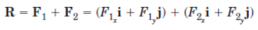
When two or more vectors act concurrently at a point, their combined effect is described by the resultant vector R, obtained by vector addition. Two commonly used graphical rules for addition are the parallelogram law and the triangle rule. Algebraically, vectors are often resolved into mutually perpendicular rectangular components for simple addition.
Let F1 and F2 be two concurrent force vectors acting at point O. Using the triangle rule, the line of action of F2 may be translated from O to the tip of F1 without changing the resultant; the vector from the tail of F1 to the tip of the translated F2 is the resultant R = F1 + F2.
It is convenient to express vectors in terms of their rectangular components along chosen x and y axes. If the x-y axes are orthogonal, and F has components Fx and Fy, then the vector may be written in component form as F = Fxi + Fyj, where i and j are the unit vectors along the x- and y-axes respectively.
For concurrent forces, the algebraic sum of components along each axis gives the components of the resultant. The notation ΣFx means "the algebraic sum of the x scalar components". Components may be positive or negative depending on the chosen sign convention; for example, a component directed opposite to the positive axis is negative.
The component method may be used to derive the magnitude and direction of the resultant. In symbols, for two forces F1 and F2,
From the component sums we can conclude the resultant magnitude and orientation by applying the Pythagorean relation and inverse tangent to the component pair:
(2/4)
Resolving vectors into rectangular components - practical notes
- When resolving a vector F that makes an angle θ with the positive x-axis, the rectangular components are Fx = F cos θ and Fy = F sin θ, with signs determined by the direction of the components relative to the chosen positive axes.
- If a vector is given graphically, inspection of right triangles (for example, common integer triples like a 3-4-5 triangle) often yields cos θ and sin θ without computing θ explicitly.
- For vectors that are not aligned with the coordinate axes, compute components along the chosen axes by projecting the vector onto the axes using cosines and sines of the included angles, or by expressing the vector as the product of its magnitude and a unit vector in its direction.
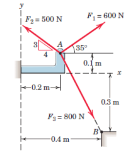
Sample Problem 2/1
The forces F1, F2, and F3, all of which act on point A of the bracket, are specified in three different ways. Determine the x and y scalar components of each of the three forces.
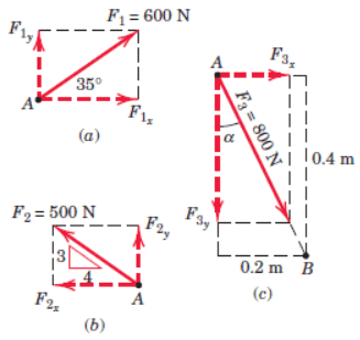
Solution. The scalar components of F1, from Fig. a, are
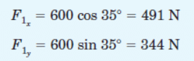
Ans
The scalar components of F2, from Fig. b, are
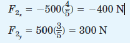
Ans
Note that the angle which orients F2 to the x-axis need not be calculated explicitly if the cosine and sine values are available by inspection (for example, from a 3-4-5 triangle). Also note that the x scalar component of F2 is negative by inspection because it points opposite to the positive x-axis.
The scalar components of F3 can be obtained by first computing the angle α of Fig. c.
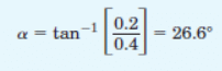
Then,
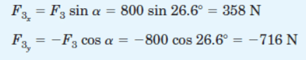
Ans
Alternatively, write F3 as the product of its magnitude and a unit vector nAB in the direction of line segment AB:
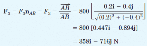
The required scalar components are then
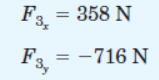
Ans
These component values agree with the results obtained by the trigonometric method above.
Sample Problem 2/2
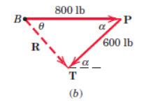
Combine the two forces P and T, which act on the fixed structure at B, into a single equivalent force R.
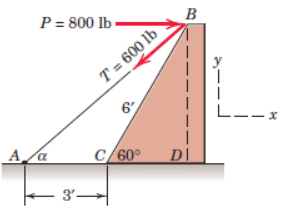
Graphical solution. Construct the parallelogram for the vector addition of T and P. Use a convenient scale (for example, 1 in. = 200 lb is suitable for regular paper; the original illustration used 1 in. = 800 lb, which is less convenient for accuracy). Determine the angle α prior to construction from the given geometry, then construct the parallelogram and measure the resultant.
Measurement of the length and direction of R gives the approximate results
R = 525 lb θ = 49° Ans
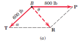
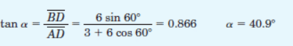
Geometric solution. Form the triangle of vector addition (one side for each vector and the resultant closing the triangle). Compute the included angle α as above and apply the law of cosines.
R² = (600)² + (800)² - 2(600)(800) cos 40.9° = 274,300
R = 524 lb Ans
Use the law of sines to determine the angle θ which orients R. Thus,
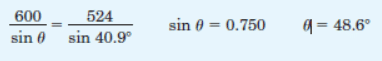
Ans
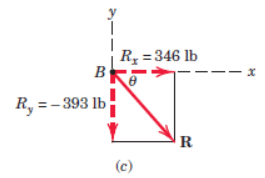
Algebraic solution. Select an x-y coordinate system on the figure and resolve each force into components along the axes. Sum the components to obtain the resultant components.
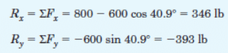
The magnitude and direction of the resultant force R are then
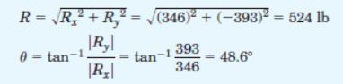
Ans
The resultant R can also be written in vector component notation as
R = Rxi + Ryj = 346i - 393j lb Ans
Sample Problem 2/3
The 500-N force F is applied to the vertical pole as shown. (1) Write F in terms of the unit vectors i and j and identify both its vector and scalar components. (2) Determine the scalar components of the force vector F along the x′- and y′-axes. (3) Determine the scalar components of F along the x- and y′-axes.
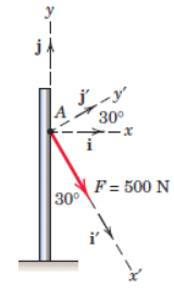
Solution.
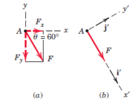
Part (1).
Express F in rectangular components by projecting on the x and y axes.
F = (F cos θ) i - (F sin θ) j
Substitute the given numerical values:
F = (500 cos 60°) i - (500 sin 60°) j
F = (250 i - 433 j) N Ans
The scalar components are Fx = 250 N and Fy = -433 N. The vector components are Fx = 250 i N and Fy = -433 j N.
Part (2).
From Fig. b, the force is aligned with the x′-axis, so
F = 500 i′ N
Therefore, the scalar components are
Fx′ = 500 N
Fy′ = 0
Part (3).
The components of F in the x- and y′-directions are non-rectangular; obtain them by completing the parallelogram shown in Fig. c and applying the law of sines to the formed triangle.
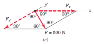
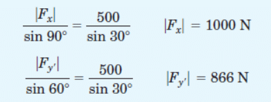
The required scalar components are then
Fx = 1000 N
Fy′ = -866 N Ans
Summary and practical remarks
- Always state the coordinate axes and sign convention before resolving vectors; positive and negative signs of components follow directly from these choices.
- Graphical methods (parallelogram or triangle) provide good visual insight and are useful for approximate results and checks, but algebraic component methods give precise results suitable for calculation and further analysis.
- A vector may be expressed as magnitude times a unit vector in its direction, or as the sum of its rectangular components multiplied by the unit vectors i and j.
- Sliding, free and fixed vectors are important distinctions when modelling forces on rigid and deformable bodies; always choose the appropriate representation for the problem at hand.
FAQs on Scalars & Vectors
| 1. What is the difference between scalars and vectors in civil engineering? |  |
| 2. How are scalars and vectors used in structural analysis in civil engineering? | |
| 3. Can you provide an example of a scalar quantity commonly encountered in civil engineering? | |
| 4. What are some examples of vector quantities in civil engineering? | |
| 5. How are scalars and vectors used in surveying and geotechnical engineering? | |


