Parallel Operation of Two Generators

Introduction
When two synchronous generators are connected in parallel to supply a common load, small differences in their angular positions (electrical phase) produce circulating currents and an internal torque that tends to restore synchronism. This restoring interaction is called synchronizing power (or synchronizing torque when expressed as torque). The synchronizing action makes parallel operation inherently stable within limits determined by the machines' reactances and the prime-mover control (governor) characteristics.
Basic physical idea
Consider two synchronous machines, labelled 1 and 2, connected in parallel and delivering power to the same external load. With respect to the supply/load busbars their generated e.m.f.s (internal generated voltages) are normally intended to be in phase. With respect to the local loop formed by the two armature windings, the e.m.f.s may be in near opposition. If one machine (say machine 1) momentarily accelerates so that its internal e.m.f. leads that of machine 2 by a small angle, a phase difference develops between the two internal e.m.f.s. This phase difference produces a circulating or local e.m.f. in the closed circuit of the two armatures and causes a circulating current Is to flow between the machines.
The circulating current flows through the synchronous impedances of the machines. Because the synchronous armature impedance is usually predominantly reactive (Xs ≫ r), the current Is lags the circulating e.m.f. by an angle close to 90°. As a result, the current leaving the faster machine is nearly in phase with its internal e.m.f. and enters the slower machine nearly in opposition to its internal e.m.f. Consequently the faster machine supplies additional electrical power to the slower machine (so the faster one is further loaded and the slower one is driven). This exchange of power produces a restoring torque that tends to reduce the phase difference and return both machines to synchronous running.
Phasor relation and synchronizing power
For two machines with internal generated e.m.f.s E1 and E2 (phasor magnitudes) and an electrical angular displacement δ between their internal e.m.f.s, the synchronizing power developed between them is given (for the usual model where synchronous reactance dominates) by the standard relation:
Ps = (E1·E2 / Xs) · sin δ
where Xs is the synchronous reactance (or the effective reactance in the path of the circulating current). Important points:
- Ps is proportional to sin δ and so is approximately linear with δ for small δ.
- The maximum synchronizing power magnitude is Ps,max = E1·E2 / Xs, occurring at δ = 90°.
- If Xs is largely reactive (as in practical machines), the circulating current lags the circulating e.m.f. by an angle close to 90° and the above expression gives the active power exchanged as synchronizing power.
The argument in the classic description (qualitative) notes that the local e.m.f. arising from the phase difference is partly opposed by the synchronous reactances, so the circulating current lags by θ = arctan(Xs/r) ≈ 90° when reactance predominates. The effect is that the faster machine delivers electrical power to the slower one until speeds (and the internal phase) are again aligned.
Consequences for stability
Within the limits set by Ps,max, the two machines cannot be driven permanently out of step by small perturbations: any small angular divergence produces a synchronizing power that tends to restore synchronism. If the machines are too weakly coupled (large Xs, small E1·E2/Xs) or the perturbation is large enough to produce δ beyond the stable region, loss of synchronism (out-of-step) can occur.
If the armature impedance were not predominantly reactive (i.e., if resistance were large compared with reactance), the circulating current would not lag by near 90° and would not supply the required active power component to slow the faster machine and accelerate the slower one; stable parallel operation would then be compromised.
Operation under load and circulating currents
When both machines supply an external load and are equally loaded initially, a small phase displacement between their internal e.m.f.s produces the same type of synchronizing current as in the no-load case. The synchronizing current redistributes the load: the faster machine takes slightly more of the external load while the slower machine takes slightly less, until the angle settles at a value that balances synchronizing power and mechanical torque supplied by prime movers.
Notation often used: I1, I2 are the load currents before phase displacement, and I1′, I2′ are the currents after synchronizing circulation Is has superimposed. The circulating current adds algebraically to each machine's external load current (vectorially), altering the share of the load for each generator.
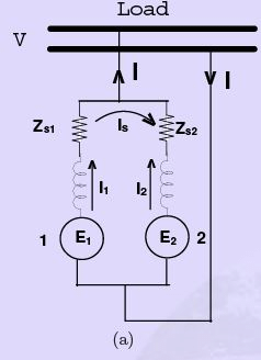
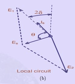
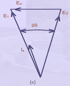
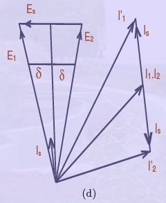 Figure 35: Parallel operation
Conditions required before paralleling
To safely and satisfactorily close the parallel breaker between two synchronous generators the following conditions must be satisfied:
- Same frequency - the incoming machine's frequency must match the bus frequency.
- Same phase sequence - for three-phase machines the phase rotation must be identical.
- Similar voltage magnitude - the rms terminal voltages should be equal or very near equal.
- Small phase angle difference - the phase angle between the incoming generator and the bus should be close to zero when the breaker is closed (synchronoscope should indicate 'in-phase').
- Synchronising check / protection - synchronising relays or checks to prevent closing when conditions are unsafe.
Common practical synchronisation devices or methods are the synchronoscope and the lamp (dark-light) method, and protective synchonising/iscochronous relays. The usual procedure is to adjust prime-mover speed and excitation so that frequency, voltage and phase align, then close the breaker when the phase difference is near zero (or when lamps go dark in the lamp method).
Load sharing: active and reactive power
Once paralleled, the way active (real) and reactive power are shared between machines depends on different controls:
- Active power sharing is mainly governed by the prime-movers (governors). Any change in mechanical input power or governor setting changes the steady angle δ and hence the active power delivered by each machine. With droop (speed-droop) governors the machines share load in proportion to their droop and power ratings; identical governors produce proportional sharing according to ratings.
- Reactive power sharing is primarily governed by machine excitation. Increasing the excitation of a generator increases its terminal voltage and causes it to supply more reactive (leading or lagging depending on load power factor) power to the bus. Thus excitation controls are used to regulate reactive power sharing.
If the governors or excitation characteristics of the machines are not identical, the steady share of real and reactive power will reflect those characteristic differences rather than the nameplate ratings. Synchronous machines must run at the same speed; therefore load sharing is achieved by suitable adjustment of prime-mover torque and excitation settings.
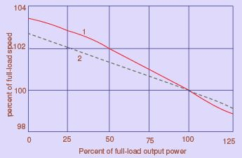 Figure 36: Governer Characteristic
The typical governor characteristic (droop) shows that to increase power output some reduction of speed (or a change in governor setpoint) occurs; with unequal governor characteristics the machines will share total load according to the relative load values at the operating speed.
Non-identical machines and special considerations
Real power stations seldom have perfectly identical machines. Differences in synchronous impedances (Zs1, Zs2), internal e.m.f.s (E1, E2), governor droop and excitation mean that parallel operation still works but the load distribution and transient behaviour depend on these parameters. Important practical points:
- When machines have different synchronous reactances and emf magnitudes, the circulating currents and synchronizing power change accordingly; the formula Ps = (E1·E2 / Xs)·sin δ is applied using the appropriate effective reactance between the internal voltages.
- It is essential to avoid closing the breaker when large phase difference or voltage mismatch exists - this causes large circulating currents, heavy torques and possible damage.
- Protection against out-of-step, reverse power, and excessive circulating current should be provided.
Practical synchronising procedure (ordered steps)
- Bring the incoming generator up to rated speed and frequency close to the bus frequency.
- Check phase sequence with a phase-sequence indicator.
- Adjust excitation of the incoming generator so that its terminal voltage magnitude matches the bus voltage.
- Observe a synchronoscope or use the lamp method to judge phase angle; slightly raise the incoming machine speed so that its internal e.m.f. leads slightly (so closing at the correct instant is possible).
- Close the breaker when the synchronoscope indicates in-phase (zero phase displacement) or when lamps in the lamp method go dark; immediately verify smooth transfer and that protective synchronising relays are satisfied.
- Adjust governor and excitation settings for desired load sharing and check for circulating currents or unusual oscillations.
Limits and failure modes
Key limitations and failure modes include:
- Exceeding Ps,max (for a given δ approaching 90°) can lead to loss of synchronism.
- Large circulating currents during paralleling or due to persistent mismatch can cause excessive heating in armature windings.
- Different governor droop characteristics can cause poor load sharing or hunting; insufficient damping may cause sustained oscillations.
- Poor excitation control will result in undesirable reactive power flows and voltage regulation problems on the common bus.
Summary
Parallel operation of synchronous generators relies on the natural synchronizing power that appears when small phase differences develop between their internal e.m.f.s. This synchronizing power, which depends on machine e.m.f. magnitudes and synchronous reactance, tends to restore machines to the same electrical angle and maintain stable parallel operation within limits. Proper synchronising procedure, correct excitation and governor settings, and adequate protection are essential for safe and satisfactory sharing of active and reactive loads.
FAQs on Parallel Operation of Two Generators
| 1. What is the purpose of parallel operation of two generators? |  |
| 2. How does parallel operation of generators work? | |
| 3. What are the benefits of parallel operation of generators? | |
| 4. What precautions should be taken during parallel operation of generators? | |
| 5. Can generators with different power ratings be operated in parallel? | |


 | Explore Courses for Electrical Engineering (EE) exam |
 | Get EduRev Notes directly in your Google search |