Synchronous Motor - 1

Principle of operation
In a three-phase synchronous machine, the armature winding is placed in the stator and the field winding is placed on the rotor. When the stator armature winding is supplied from a balanced three-phase AC source and the rotor field winding is excited from a suitable DC source, two magnetic systems exist simultaneously:
- a stationary magnetic field produced by the DC-excited rotor poles (for convenience a salient-pole rotor is assumed here); and
- a rotating magnetic field produced by the three-phase currents in the stator armature winding, which rotates at the synchronous speed. The synchronous speed is given by n_s = 120 f / P where f is supply frequency (Hz) and P is the number of poles.
The stator rotating field establishes successive north and south pole regions at any fixed stator location; a pole at a point becomes the opposite polarity after half a cycle (time = 1/(2f)). If, at one instant, a stationary rotor pole of one polarity (say a south pole) is aligned with an unlike pole of the stator rotating field (north), the two poles attract and attempt to maintain alignment. This attraction produces a torque on the rotor tending to make it follow the rotating stator field.
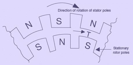
Figure 50: Force of attraction between stator poles and rotor poles - resulting in production of torque in clockwise direction
Because of the rotor's mechanical inertia it cannot immediately match the instantaneous motion of the stator field. Meanwhile the stator pole changes polarity quickly (within half a cycle) and becomes a like pole; the earlier attraction becomes repulsion and produces torque in the opposite direction. Thus the rotor is subjected to an alternating electrical torque that changes sign at twice the electrical frequency. As this alternating torque changes much faster than the rotor mechanical time constant, the rotor cannot follow these rapid reversals and remains effectively stationary unless some provision is made to bring it near synchronous speed.
Figure 51: Force of repulsion between stator poles and rotor poles - resulting in production of torque in anticlockwise direction
If the rotor is brought near the synchronous speed by an external means (for example by a small auxiliary motor called a pony motor), the rotor poles can lock (or pull into step) with the rotating stator poles. Once pulled into step the rotor will remain locked to the rotating field and run at synchronous speed even if the pony motor is disconnected.
Because a synchronous rotor cannot develop sufficient starting torque on its own from standstill, some special starting method must be provided. Typical approaches are: running the stator field at reduced frequency, starting with an external motor, or using damper (amortisseur) windings. These methods are described in the next sections.
Methods of starting a synchronous motor
Three commonly used methods to start a synchronous motor are listed below. Each method is used according to machine size, application, and availability of control equipment:
- Reduce the rotating field speed by reducing the supply frequency (used with variable-frequency drives / inverter systems).
- Use an external prime mover (pony motor) to accelerate the rotor close to synchronous speed, then synchronise and connect to supply.
- Use damper (amortisseur) windings provided on the rotor so that the motor starts like an induction machine and then is pulled into synchronism when the field is applied.
Each method is described in detail below.
Motor starting by reducing the supply frequency
If the stator rotating magnetic field is made to rotate sufficiently slowly, the rotor can easily accelerate and lock with it. This requires a low-frequency supply for starting, then gradual increase of frequency to the rated value (typically 50 or 60 Hz) for normal operation.
Historically a variable-frequency generator was required to supply the low frequency; this was impractical for most applications. Modern solid-state power electronics-rectifier-inverter sets and cycloconverters-permit easy conversion of fixed-frequency mains to controlled variable-frequency, variable-voltage supplies. Using such a variable-frequency drive (VFD) the motor speed can be ramped from a small fraction of a hertz up to rated frequency; the motor can therefore be started at low frequency and smoothly accelerated to synchronous speed.
When operating below rated speed, the internally generated counter EMF E_a (= Kφω) is lower. To limit stator current to rated values the applied terminal voltage must be reduced proportionally to the frequency; practical VFDs typically implement a V/f control law (voltage approximately proportional to frequency).
Motor starting with an external motor (pony motor)
In this method an auxiliary motor (pony motor) is coupled to the synchronous rotor shaft and accelerates the rotor to near synchronous speed. The synchronous machine may be run as a generator and synchronised (paralleled) with the supply; after synchronisation the pony motor is disconnected. When the pony motor is switched off the rotor magnetic field momentarily falls behind the stator rotating field and the machine assumes motoring action while locked to the system. The synchronous motor then picks up load as a normal synchronous motor.
This method is convenient when the synchronous machine is part of a motor-generator set or when a small starter motor or exciter mounted on the shaft is available. The pony motor needs only to overcome mechanical inertia (no load is applied until after paralleling), so it can be much smaller than the synchronous motor it starts.
Motor starting by using damper (amortisseur) winding
Many large synchronous machines include damper windings (also called amortisseur windings): shorted copper bars embedded in the pole faces and shorted by end rings (like a squirrel-cage). When the stator is energised from the supply, these damper bars produce induced currents if the rotor relative speed differs from synchronous speed, so the machine initially behaves like a three-phase induction motor for starting. The applied voltage should be limited on starting to restrict inrush current, as with any induction start.
As the rotor approaches synchronous speed the DC field is applied and the rotor is drawn (pulled) into synchronism. Damper windings also provide damping for small oscillatory disturbances and help stabilise the rotor under varying periodic loads.
Behaviour of a synchronous motor
The steady-state behaviour is analysed with an equivalent per-phase circuit similar to that used for the synchronous generator, but with current direction into the armature from the supply. The equivalent circuit, phasor relations and resulting power expressions explain how armature current, torque (or electromagnetic power), power factor and stability depend on excitation and load.
Equivalent circuit model and phasor diagram of a synchronous motor
The per-phase equivalent circuit for a cylindrical-rotor synchronous motor (armature resistance R_a, leakage reactance X_l, internal induced EMF E_f and applied terminal voltage V_T) is shown in the figure.
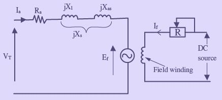
Figure 52: Equivalent-circuit model for one phase of a synchronous motor armature
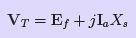
Applying Kirchhoff's voltage law around the phase circuit gives the basic phasor relation between applied voltage V_T, the internal induced voltage E_f and the impedance drop Z_s I_a. In compact form this may be written as an image expression in the original text.
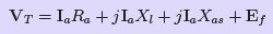
(58)
Combining reactances, synchronous reactance X_s = X_l + X_m (or the appropriately combined reactance) yields the synchronous impedance Z_s. The combining step and a corresponding image expression appear here.
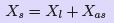
(59)
Substituting Eqn. (59) in Eqn. (58) gives the phasor equation relating V_T, E_f and I_a as shown in the source images.

where:
- R_a = armature resistance (Ω/phase)
- X_l = armature leakage reactance (Ω/phase)
- X_s = synchronous reactance (Ω/phase)
- Z_s = synchronous impedance (Ω/phase)
- V_T = applied terminal voltage per phase (V)
- I_a = armature current per phase (A)
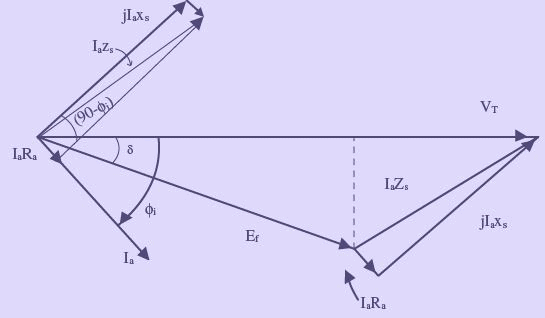
Figure 53: Phasor diagram corresponding to the equivalent-circuit model
The phasor diagram is used to determine the internal generated EMF and relative phase relations. The angle δ between V_T and E_f is the torque angle (also called the load angle or power angle). This angle controls the developed electromagnetic torque (or power) for a given excitation.
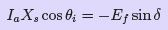
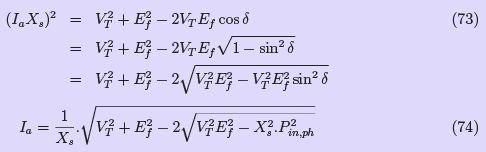
Synchronous-motor power equation
For practical (non-very small) synchronous machines the armature resistance R_a is small compared with X_s and is often neglected in analytical expressions. Under that approximation the phasor equation simplifies (original equations shown as images in the source).
(62)
From the simplified phasor diagram the relation between voltages and currents can be arranged to give an expression for active power per phase developed by the synchronous motor. The intermediate algebraic step is shown in the images.
(63)
Multiplying through by V_T and rearranging yields (image):
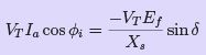
(64)
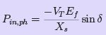
The left side of Eqn. (64) represents the active power input per phase and, neglecting small resistive losses, also equals the electromagnetic power developed per phase. Thus the developed power per phase is given by the image expression in the original text.
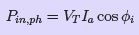
(65)
Or
(66)
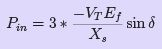
Thus, for a three-phase synchronous motor, total developed power is
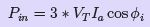
(67)
or
(68)
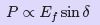
Equation (66) (or its three-phase form) is the synchronous-machine power equation, which shows that electromagnetic power developed is proportional to |E_f||V_T| sin δ / X_s, i.e. proportional to excitation, terminal voltage and the sine of the torque angle, inversely proportional to synchronous reactance. For constant supply voltage and frequency useful proportionalities are:

(69)
(70)
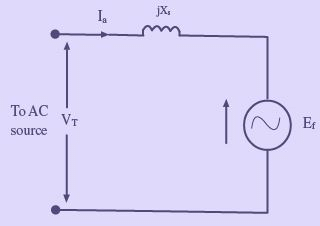
Figure 54: Equivalent-circuit of a synchronous motor, assuming armature resistance is negligible
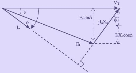
Figure 55: Phasor diagram model for a synchronous motor, assuming armature resistance is negligible
Effect of changes in load on armature current, power angle, and power factor
Assume terminal voltage, supply frequency and field excitation E_f are held constant. If shaft (mechanical) load is increased, the motor must develop more electromagnetic torque. From the power equation E_f sin δ must increase; hence δ increases, meaning the rotor lags the stator field by a larger power angle. Increased δ increases stator current magnitude and changes the power factor.
The phasor diagrams in the source illustrate an initial operating condition and the new steady state after doubling shaft load. When load is increased the E_f phasor tip traces a circular locus and its phase relative to V_T changes. For a fixed excitation an increase in mechanical load usually reduces the angle φ_i (angle between I_a and V_T), and therefore increases the power factor (power factor becomes less lagging).
As load increases the rotor angle δ increases until a limit is reached where a further increase in δ does not produce corresponding increase in torque; the rotor then pulls out of synchronism. For a cylindrical-rotor machine the theoretical maximum torque occurs near δ ≈ 90°, and this maximum torque is called the pull-out torque. In practice motors are not operated close to δ = 90° because armature current would be excessively large.
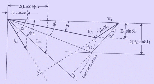
Figure 56: Phasor diagram showing effect of changes in shaft load on armature current, power angle and power factor of a synchronous motor
Effect of changes in field excitation on synchronous motor performance
Change of rotor excitation E_f at a constant shaft load (and constant V_T, f) alters the phasor relations and so changes armature current and power factor, while the machine continues to run at synchronous speed. From the power equation, for constant shaft load E_f sin δ is constant, so if E_f is increased transiently the rotor accelerates and δ decreases until a new steady value of δ satisfies the required E_f sin δ.
Graphically the tip of the E_f phasor moves along a straight line roughly parallel to V_T when excitation is varied with shaft load constant; the tip of the I_a phasor traces a line perpendicular to V_T. Increasing excitation can move the current phasor from a lagging to a leading angle with respect to V_T.
The field current that produces unity power factor (I_a in phase with V_T) is called normal excitation. Field stronger than normal is over-excitation (|E_f| > |V_T|) and field weaker than normal is under-excitation. A heavily over-excited synchronous motor operating unloaded behaves as a synchronous condenser and supplies reactive (leading) VARs to the system.

(71)

(72)
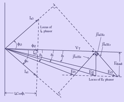
Figure 57: Phasor diagram showing effect of changes in field excitation on armature current, power angle and power factor of a synchronous motor
V curves
Plots of armature current magnitude |I_a| versus field current (or excitation) at constant shaft load are called V curves. Typically they show a minimum armature current at the excitation that yields unity power factor; on either side of this excitation armature current increases (forming a V-shaped curve). For higher mechanical loads the minimum point shifts, and more excitation is required to hold unity power factor.
The leftmost point of the family of V curves corresponds to the stability limit (δ = -90°). Any reduction in excitation below that stability limit for a given load may make the developed torque insufficient and the machine will pull out of synchronism.
The V curves can be obtained experimentally by varying field current at constant mechanical load and recording I_a, or computed from the phasor relations. The mathematical form used to generate the example plots is given by an expression shown as an image in the source text; the plotted family in the source used data for a three-phase 10 hp synchronous motor with V_ph = 230 V and X_s = 1.2 Ω/phase.
Equation form used for V curves (image as supplied)
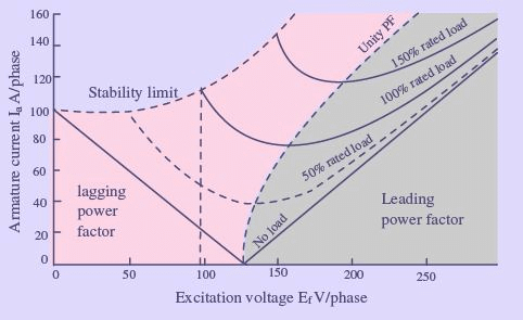
Figure 58: Family of representative V curves for a synchronous motor
Synchronous-motor losses and efficiency
Power flow through a synchronous motor from stator input to shaft output includes several loss components. The standard power-flow diagram and loss terms are shown below.

(75)
Total motor losses include:
- P_scl - stator copper (I2R) loss
- P_fcl - field (rotor) copper loss (I2R in field winding)
- P_core - core (iron) loss (hysteresis + eddy)
- P_f,w - friction and windage loss
- P_stray - stray load loss (mechanical/electromagnetic irregularities)
Except during rapid transients where magnetic energy is stored or released, the field winding electrical energy is dissipated as I2R loss in the field circuit; this is included in total losses.
Overall efficiency is the ratio of shaft output to input electrical power:
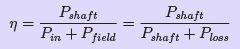
(76)
Manufacturers normally quote overall efficiency at rated load and at a few typical load points. Determining the detailed loss breakdown experimentally requires specialised tests. A practical approach to estimate shaft power is to subtract calculated stator and field copper losses from input power to obtain developed mechanical power, then subtract mechanical losses to obtain shaft output.
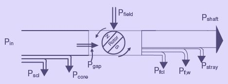
Figure 59: Power flow diagram for a synchronous motor
FAQs on Synchronous Motor - 1
| 1. What is a synchronous motor? |  |
| 2. How does a synchronous motor work? | |
| 3. What are the advantages of a synchronous motor? | |
| 4. What are the applications of synchronous motors? | |
| 5. What is the difference between synchronous and asynchronous motors? | |


 | Explore Courses for Electrical Engineering (EE) exam |
 | Get EduRev Notes directly in your Google search |