A/D and D/A Converters - Digital Electronics, Electronics and Experimental Methods, CSIR-NET Physic | Physics for IIT JAM, UGC - NET, CSIR NET PDF Download
DigitaltoAnalog Conversion
A digital to analog (D/A) converter (DAC) is a chip or circuit that converts a digital number into an analog voltage or current. D/As are used to control devices that require a range of control voltages or currents such as electroacoustic transducers (speakers), some types of variablespeed motors, and many other applications where an analog signal output is required. The most common application is to [re]create waveforms from digital signals – for example in CD players.
D/A Converters
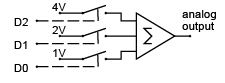
A D/A converter can be visualized as a circuit that adds up a number of voltages under the control of a digital signal. Each voltage can be turned on and off by an electronic switch which is controller by the digital input. The circuit below shows a 3-bit D/A consisting of a summing amplifier fed by three different voltages. Depending on which switches are closed, the output can range from 0 to 7 volts. By using digital signals to control the switches we can build a circuit whose output voltage is proportional to the digital value.
D/A Converter Specifications
Many different DigitaltoAnalog converters are commercially available, both as chips and as subsystems (modules, boards, etc). To select the right D/A converter it is necessary to understand D/A specifications. The most important specs are resolution and settling time. In some applications other specifications such as slew rate, linearity, monotonicity may also be important. There are also various types of digital and analog interfaces. Since different manufacturers use different definitions for some of these specifications it is important to check each manufacturer’s definitions when comparing devices.
The resolution (output step size) is given by the output voltage range divided by the number of possible output levels. An N bit DAC can output 2N different levels in 2N -1 steps. N ranges from 6 (for simple highspeed converters) up to 20 or more (for precision instrumentation).
The accuracy is the maximum difference between the output and the theoretical output. This is typically (but not always) this is approximately the same as the resolution.
The settling time is the time it takes the output to reach a percentage (e.g. 99%) of the final value.
Values can range from hundreds of milliseconds for highprecision units to nanoseconds for devices used in highfrequenc y waveform generators.
The linearity is the maximum difference between the output and a linear interpolation between the minimum and maximum values. This is usually on the order of 1 / 2N .
The output is monotonic if an increase in the digital input always causes an increase in the analog out put. This is usually guaranteed.
There are various types of digital DAC interfaces.
Some devices have chipselect and address pins and can be easily interfaced to microcomputers as if they were peripheral chips. Other devices omit the registers and thus require additional logic to interface to a microprocessor.
There are various types of DAC output circuits.
Some are designed to generate a current (rather than a voltage) that is proportional to the digital input. Often the DAC is simply is a set of N switches and an accurate voltage divider network and an external voltage reference must be supplied.
Finally, there are different ways of manufacturing DAC devices. In addition to the standard monolithic ICs, there are also hybrid devices that mount IC chips together with a small number of discrete devices into an IClike package. This allows the manufacturer to adjust (“trim”) each device during manufacture to obtain higher precision. There are also DAC modules in which a D/A converter built from discrete components is packaged in a sealed module. Hybrids and modules tend to be used for higherperformance devices.
Analog to Digital Converters
A controller often has to measure a physical quantity, for example temperature, pressure, force, etc.
A sensor, often called a transducer, is used to convert this physical quantity into an electrical signal (current or voltage). This electrical signal must then be converted into a binary number so that the digital controller can use it. An analog to digital (A/D) converter (ADC) performs this function.
Comparators
The simplest type of ADC is a comparator. As its name indicates, a comparator compares two analog inputs (say vin and vref ) and outputs a logic signal which is high if vin is greater than vref or low otherwise. Comparators are available as ICs, often with two or four units in one IC.
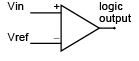
The comparator can be considered to be a onebit ADC since it’s output tells us whether the input voltage is above or below the reference voltage.
Although a comparator does not offer much precision, it is often sufficient since for many applications it’s only necessary to determine whether some quantity is above or below some threshold. Comparators also form the basis of other types of A/D converters as will be described below
Types of A/D Converters
Flash Converters
A simple way to get better (more bits of) resolution is to use more comparators. As shown below for a 2bit flash converter we can use 2N - 1 comparators, supplying them with reference voltages that are equally spaced over the desired conversion range. The other comparator inputs are connected to the input signal.
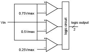
All of the digital outputs connected to reference voltages below the input signal will be true and all of the outputs with reference signals above the input signal level will be false. The output logic circuit converts these 2N - 1 binary values into an N bit number.
Successive Approximation Converters
Another approach is to use a D/A converter to generate the reference voltage and a single comparator to compare this voltage and the input. A digital circuit can step the D/A output up through the possible values until the comparator indicates that the reference signal is greater than the input signal. The digital input to the D/A would correspond to the voltage step that is the nexthighest to the input signal. This approach would take up to 2N comparisons.
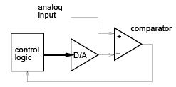
A faster method is to use a binary search. The control circuit first tests whether the analog input is greater than or less than half of the D/A output range. This fixes the value of the most significant bit.
Then the controller tests whether the value is greater than or less than the halfway point of the remaining range. This sets the next mostsignificant bit. The process is repeated until the values of all of the bits are determined. The time required for this method is about N times the D/A settling time.
This method is slower than a flash converter but reduces the number of comparators required. Successive approximation converters are probably the most common type of generalpurpose ADCs.
Single and DualSlope Converters
A different approach, commonly used in highprecision lowspeed ADCs, is to use the input signal to charge up a capacitor until the capacitor voltage reaches a fixed threshold. A digital circuit measures the time required to reach this threshold by counting the number of pulses from a fixedfrequency clock.
This approach is often used in slow, lowprecision converters because very little hardware (one comparator and one digital output to reset the capacitor) is required.
One problem with this approach is that very accurate components are required to obtain precise results (e.g. the capacitors and resistors used in the integration). A slightly different approach is to use the input voltage to charge up the capacitor as before, but to do this for a fixed time. Then the capacitor is discharged by a reference voltage and the digital control circuit measures the time required to completely discharge the capacitor. The ratio of the discharge time to the charging time is the ratio of the unknown to the known voltage. This dualslope method is independent of the values of the integrator components because the same circuit is used for charging and discharging.
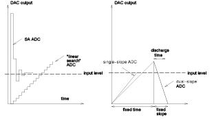
This method can be quite slow since sufficient conversion time must be allowed the counter must count up to 2N . However since this method is quite accurate it is often used in high precision (e.g. 16 bit) converters.
Voltage - to - Frequency Conversion
Yet another method of converting from a voltage to a number is to use the analog voltage to control the frequency of an oscillator. Various circuits and IC’s are available that oscillate at a frequency proportional to an input voltage. A counter can be used to count the number of pulses produced in a fixed time and this becomes the digital output.
This approach is also relatively slow but also requires little hardware.
A/D Specifications
The most important specifications for an A/D converter, as for a D/A converter, are the resolution and accuracy (number of bits) and the conversion speed (in microseconds or milliseconds). Converters are available with resolutions from 6 (for some very fast flash converters) to 18 or more (slow dualslope models for highprecision applications).
Other specifications, such as linearity and monotonicity are similar to the specifications for D/A converters.
A/D converters also differ in the input voltage ranges that they can convert and in their digital output interfaces.
A/D Digital Interfaces
As with D/A converters, A/D converters are available as chips (monolithic or hybrids) that can be interface easily to a microcomputer as if they were standard peripheral chips. Most types of D/A converters need to be supplied with a periodic clock signal, a “start conversion” signal and they generate a “conversion complete” status signal when the conversion is done. The software that handles the A/D must give the command to start the conversion (e.g. by setting a control bit), and then wait until the status bit indicates that the conversion is complete before reading the result.
Successiveapproximation ADCs often provide their outputs in a serial format, one bit at a time, as the conversion takes place.
Sample and Hold
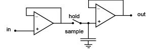
If the analog signal changes while a conversion is taking place, the ADC could produce an incorrect result. A device called a sampleandhold can be used before the ADC to hold the signal at the input to the ADC constant. This device samples the analog signal at its input for a short time and then holds that value fixed at its output until the next sample is required.
The diagram below shows how the device works. An electronic switch is used to connect the analog input to a capacitor during the sampling time. During the “hold” time the switch is opened. An output amplifier with a very high input impedance is used in order to avoid discharging the capacitor during the hold time.
Multiplexers
Often several analog signals need to be monitored. If a sufficiently fast A/D converter is available, its input can be switched between the various signals using an electronic singlepole multiplethro w switch.
This device is called a multiplexer. Many ADC chips have builtin multiplexers and S/H circuits.
Differential Amplifiers
Often the quantity of interest is the difference between two voltages (e.g. the voltage drop across a resistor) rather than the difference between a signal and ground. The circuit shown below combines an inverting and a nonin verting amplifier into a device called a differential amplifier. This circuit is also useful when an undesired signal (noise) is present on both inputs. Since the differential amplifier only responds to the difference between the two voltages, it will not respond to this commonmode noise.
LowPass Filters
Often the signal of interest is changing slowly (e.g. the voltage output of a battery as it discharges) but has an additional higherfrequenc y component superimposed on it (e.g. voltage fluctuations due to a rapidly changing load). A circuit called a lowpass filter will allow the slowlychanging (lowfrequenc y) signal component to pass through to the output while removing or attenuating the fastchanging (highfrequency) component. Filters (lowpass as well as other types) can be built using opamps, resistors and capacitors.
FAQs on A/D and D/A Converters - Digital Electronics, Electronics and Experimental Methods, CSIR-NET Physic - Physics for IIT JAM, UGC - NET, CSIR NET
| 1. What is the purpose of an A/D converter? |  |
| 2. How does an A/D converter work? | |
| 3. What is the function of a D/A converter? | |
| 4. How does a D/A converter work? | |
| 5. What are the applications of A/D and D/A converters? | |

|
4.64/5 Rating |

|
Dec 26, 2024 Last updated |

|
Explore Courses for Physics exam
|
|
UGC - NET
,Semester Notes
,Previous Year Questions with Solutions
,CSIR-NET Physic | Physics for IIT JAM
,MCQs
,Sample Paper
,Electronics and Experimental Methods
,A/D and D/A Converters - Digital Electronics
,Extra Questions
,CSIR NET
,CSIR NET
,past year papers
,Electronics and Experimental Methods
,Electronics and Experimental Methods
,Exam
,Viva Questions
,video lectures
,Objective type Questions
,ppt
,practice quizzes
,A/D and D/A Converters - Digital Electronics
,UGC - NET
,Summary
,CSIR-NET Physic | Physics for IIT JAM
,A/D and D/A Converters - Digital Electronics
,UGC - NET
,CSIR NET
,CSIR-NET Physic | Physics for IIT JAM
,Free
,study material
,mock tests for examination
,shortcuts and tricks
,Important questions
;


A/D and D/A Converters - Digital Electronics, Electronics and Experimental Methods, CSIR-NET Physic Free PDF Download
Importance of A/D and D/A Converters - Digital Electronics, Electronics and Experimental Methods, CSIR-NET Physic
A/D and D/A Converters - Digital Electronics, Electronics and Experimental Methods, CSIR-NET Physic Notes
A/D and D/A Converters - Digital Electronics, Electronics and Experimental Methods, CSIR-NET Physic Physics Questions
Study A/D and D/A Converters - Digital Electronics, Electronics and Experimental Methods, CSIR-NET Physic on the App
|
© EduRev
|
Education Revolution
|


|


