Irodov Solutions: Electric Current - 2 - Airforce X Y / Indian Navy SSR PDF Download
Q. 166. The gap between the plates of a parallel-plate capacitor is filled up with two dielectric layers 1 and 2 with thicknesses d1 and d2, permittivities ε1 and ε2, and resistivities p1 and p2. A de voltage V is applied to the capacitor, with electric field directed from layer 1 to layer 2. Find σ, the surface density of extraneous charges at the boundary between the dielectric layers, and the condition under which σ = 0.
Solution. 166. 

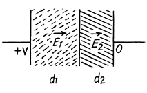


Q. 167. An inhomogeneous poorly conducting medium fills up the space between plates 1 and 2 of a parallel-plate capacitor. Its permittivity and resistivity vary from values ε1, p1 at plate 1 to values ε2, p2 at plate 2. A de voltage is applied to the capacitor through which a steady current I flows from plate 1 to plate 2. Find the total extraneous charge in the given medium.
Solution. 167. By current conservation

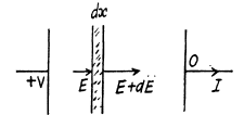
This has the solution,

Hence charge induced in the slice per unit area


Thus, 
Hence total charge induced, is by integration,

Q. 168. The space between the plates of a parallel-plate capacitor is filled up with inhomogeneous poorly conducting medium whose resistivity varies linearly in the direction perpendicular to the plates. The ratio of the maximum value of resistivity to the minimum one is equal to η The gap width equals d. Find the volume density of the charge in the gap if a voltage V is applied to the capacitor. ε is assumed to be 1everywhere.
Solution. 168. As in the previous problem

where 
By integration 
Thus 
Thus volume density of charge present in the medium


Q. 169. A long round conductor of cross-sectional area S is made of material whose resistivity depends only on a distance r from the axis of the conductor as p = α/r2, where a is α constant. Find:
(a) the resistance per unit length of such a conductor;
(b) the electric field strength in the conductor due to which a current I flows through it.
Solution. 169. (a) Consider a cylinder of unit length and divide it into shells of radius r and thickness dr Different sections are in parallel. For a typical section,

Integrating, 
or, 
(b) Suppose the electric filed inside is Ez = E0 (Z axis is along the axiz of the conductor). This electric field cannot depend on r in steady conditions when other components of E are absent, otherwise one violates the circulation theorem

The current through a section between radii (r + dr, r) is

Thus 
Hence 
Q. 170. A capacitor with capacitance C = 400 pF is connected via a resistance R = 650 Ω to a source of constant voltage V0. How soon will the voltage developed across the capacitor reach a value V = 0.90 V0?
Solution. 170. The formula is, 
or, 
or, 

Q. 171. A capacitor filled with dielectric of permittivity e = 2.1 loses half the charge acquired during a time interval τ = 3.0 min. Assuming the charge to leak only through the dielectric filler, calculate its resistivity.
Solution. 171. The charge decays according to the foumula

Here, RC = mean life = Half-life/ln 2
So, half life = T = R C In 2
But, 
Hence, 
Q. 172. A circuit consists of a source of a constant  and a resist ante R and a capacitor with capacitance C connected in series. The internal resistance of the source is negligible. At a moment t = 0 the capacitance of the capacitor is abruptly decreased η-fold. Find the current flowing through the circuit as a function of time t.
Solution. 172. Suppose q is the charge at time t. Initially 
Then at time t,

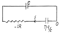
 (- sign because charge decreases)
so 

or, 
or, 

Hence, 
Finally, 
Q. 173. An ammeter and a voltmeter are connected in series to a battery with an emf  When a certain resistance is connected in parallel with the voltmeter, the readings of the latter decrease η = 2.0 times, whereas the readings of the ammeter increase the same number of times. Find the voltmeter readings after the connection of the resistance.
Solution. 173. Let r = internal resistance of the battery. We shall take the resistance of the ammeter to be = 0 and that o f voltmeter to be G.

So,  (1)
(1)
After the voltmeter is shunted
 (2)
(2)
 (3)
(3)
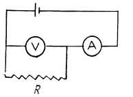
From (2) and (3) we have
 (4)
(4)
From (1) and (4)

Then (1) gives the required reading

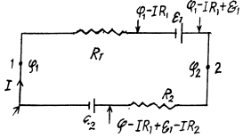
Q. 174. Find a potential difference φ1 — φ2 between points 1 and 2 of the circuit shown in Fig. 3.39 if R1 = 10 Ω, R2 = 20 Ω,  5.0 V, and
  V. The internal resist- ances of the current sources are negligible.

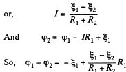
Solution. 174. Assume the current flow, as shown. Then potentials are as shown. Thus,


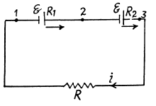
Q. 175. Two sources of current of equal emf are connected in series and have different internal resistances R1 and R2. (R2 > R1). Find the external resistance R at which the potential difference across the terminals of one of the sources (which one in particular?) becomes equal to zero.
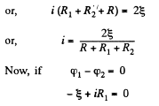
Solution. 175. Let, us consider the current i, flowing through the circuit, as shown in the figure. Applying loop rule for the circuit, - Δ φ = 0


or, 
So,  which is the required resistance.
Q. 176. N sources of current with different emf's are connected as shown in Fig. 3.40. The emf's of the sources are proportional to their internal resistances, i.e.  where a is an assigned constant. The lead wire resistance is negligible. Find:
(a) the current in the circuit;
(b) the potential difference between points A and B dividing the circuit in n and N — n links.
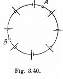
Solution. 176. (a) Current, 

Q. 177. In the circuit shown in Fig. 3.41 the sources have emf's  V and
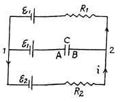
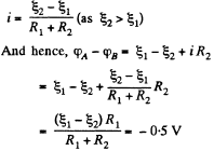
V and  and the resistances have the values R1 = 10 Ω and R2 = 20 Ω. The internal resistances of the sources are negligible. Find a potential difference φA — φB between the plates A and B of the capacitor C.
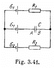
Solution. 177. As the capacitor is fully charged, no current flows through it So, current
Q. 178. In the circuit shown in Fig. 3.42 the emf of the source is equal to  = 5.0 V and the resistances are equal to R1 = 4.0 Ω and R2 = 6.0 Ω. The internal resistance of the source equals R = 0.10 Ω. Find the currents flowing through the resistances R1 and R2.

Solution. 178. Let us make the current distribution, as shown in the figure.
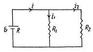

So, current through the resistor R1,

and similary, current through the resistor R2,

Q. 179. Fig. 3.43 illustrates a potentiometric circuit by means of which we can vary a voltage V applied to a certain device possessing a resistance R. The potentiometer has a length l and a resistance R0, and voltage V0 is applied to its terminals. Find the voltage V fed to the device as a function of distance x. Analyse separately the case R ≫ R0.
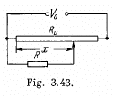
Solution. 179.

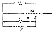


For 
Q. 180. Find the emf and the internal resistance of a source which is equivalent to two batteries connected in parallel whose emf's are equal to  and internal resistances to R1 and R2.
Solution. 180. Let us connect a load of resistance K between the points A and B (Fig.)
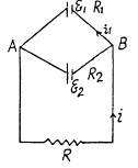
From the loop rule, Δ φ = 0, we obtain


Thus one can replace the given arrangement of the cells by a single cell having the emf  and internal resistance R0.
Q. 181. Find the magnitude and direction of the current flowing through the resistance R in the circuit shown in Fig. 3.44 if the emf's of the sources are equal to  and the resistances are equal to R1 =10 Ω, R2 = 20 Ω, R = 5.0 Ω. The internal resistances of the sources are negligible.
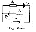
Solution. 181. Make the current distribution, as shown in the diagram
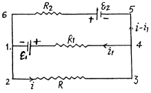
Now, in the loop 12341, applying - Δφ = 0
 (1)
(1)
and in the loop 23562,
 (2)
(2)

and it is directed from left to the right
Q. 182. In the circuit shown in Fig. 3.45 the sources have emf's  and the resistances are equal to R1 = 10 Ω, R2 = 20 Ω, R3 = 30 Ω. The internal resistances of the sources are negligible. Find:
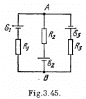
(a) the current flowing through the resistance R1;
(b) a potential difference φA — φB between the points A and B.
Solution. 182. At first indicate the currents in the branches using charge conservation (which also includes the point rule).
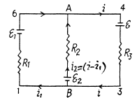
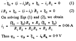
In the loops 1 BA 61 and B34AB from the loop rule, - Δ φ = 0, we get, respectively
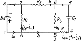
Q. 183. Find the current flowing through the resistance R in the circuit shown in Fig. 3.46. The internal resistances of the batteries are negligible.

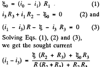
Solution. 183. Indicate the currents in all the branches using charge conservation as shown in the figure. Applying loop rule, - Δφ = 0 in the loops 1A781, 1B681 and B456B, respectively, we get
FAQs on Irodov Solutions: Electric Current - 2 - Airforce X Y / Indian Navy SSR
| 1. What is the formula to calculate electric current? |  |
| 2. How is electric current measured? |  |
| 3. What is the difference between AC and DC current? |  |
| 4. How does resistance affect electric current? |  |
| 5. What is the role of a conductor in an electric current? |  |

|
Explore Courses for Airforce X Y / Indian Navy SSR exam
|

|


