Behaviour of an AC circuit | Basic Physics for IIT JAM PDF Download
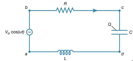
The way an AC circuit functions can be better understood by examining one that includes a source of sinusoidally varying electromotive force, a resistor, a capacitor, and an inductor, all connected in series. For this single-loop problem, only the second of Kirchhoff’s laws is needed since there is only one current. The circuit is shown in Figure 23 with the points a, b, c, and d at various positions in the circuit located between the various elements. The letters R, L, and C represent, respectively, the values of the resistance in ohms, the inductance in henrys, and the capacitance in farads. The source of the AC electromotive force is located between a and b. The wavy symbol is a reminder of the sinusoidal nature of the voltage that is responsible for making the current flow in the loop. For the potential between b and a,

Figure 23: A series LRC circuit. This type of electric circuit has an inductor, resistor, and capacitor connected in series (see text).
 (27a)
(27a)
Equation (27a) represents a potential difference that has its maximum positive value at t = 0.
 (27a)
(27a)
The direction chosen for the current i in the circuit in figure 23 represents the direction of that current at some particular time, since AC circuits feature continuous reversals of the direction of the flow of charge. The direction chosen for the current is important, however, because the loop equation must consider all the elements at the same instant in time. The potential difference across the resistor is given by Ohm’s law as
Vb -Vc=iR (27b)
For equation (27b), the direction of the current is important. The potential difference across the capacitor, Vc − Vd, depends on the charge on the capacitor. When the charge on the upper plate of the capacitor in Figure 23 has a value Q, the potential difference across the capacitor is
Vb -Vc=iR (27b)
 (27c)
(27c)
which is a variant of equation (12). One must be careful labeling the charge and the direction of the current, since the charge on the other plate is −Q. For the choices shown in the figure, the current in the circuit is given by the rate of change of the charge Q—that is, i = dQ/dt. Finally, the value of the potential difference Vd − Va across the inductor depends on the rate of change of the current through the inductor, di/dt. For the direction chosen for i, the value is
 (27d)
(27d)
The result of combining equations (27a, b, c, d) in accordance with Kirchhoff’s second law for the loop in Figure is
 (27c)
(27c)
 (28)
(28)
Both the current i and the rate of change of the current di/dt can be eliminated from equation (28), since i = dQ/dt, and di/dt = d2Q/dt2. The result is a linear, inhomogeneous, second-order differential equation with well-known solutions for the charge Q as a function of time. The most important solution describes the current and voltages after transient effects have been dampened; the transient effects last only a short time after the circuit is completed. Once the charge is known, the current in the circuit can be obtained by taking the first derivative of the charge. The expression for the current in the circuit is
 (29)
(29)
In equation (29), Z is the impedance of the circuit; impedance, like resistance, is measured in units of ohms. Z is a function of the frequency of the source of applied electromotive force. The equation for Z is
 (30)
(30)
If the resistor were the only element in the circuit, the impedance would be Z = R, the resistance of the resistor. For a capacitor alone, Z = 1/ωC, showing that the impedance of a capacitor decreases as the frequency increases. For an inductor alone, Z = ωL; the reason why the impedance of the inductor increases with frequency will become clear once Faraday’s law of magnetic induction is discussed in detail below. Here it is sufficient to say that an induced electromotive force in the inductor opposes the change in current, and it is directly proportional to the frequency.
The phase angle ϕ in equation (29) gives the time relationship between the current in the circuit and the driving electromotive force, V0 cos(ωt). The tangent of the angle ϕ is
 (31)
(31)
Depending on the values of ω, L, and C, the angle ϕ can be positive, negative, or zero. If ϕ is positive, the current “lags” the voltage, while for negative values of ϕ, the current “leads” the voltage.
The power dissipated in the circuit is the same as the power delivered by the source of electromotive force, and both are measured in watts. Using equation (23), the power is given by
 (23)
(23)
 (32)
(32)
An expression for the average power dissipated in the circuit can be written either in terms of the peak values i0 and V0 or in terms of the rms values irms and Vrms. The average power is
 (33)
(33)
The cos ϕ in equation (33) is called the power factor. It is evident that the only element that can dissipate energy is the resistance.
 (33)
(33)
|
217 videos|156 docs|94 tests
|


