NEET Previous Year Questions (2014-2025): Electromagnetic Induction


2025
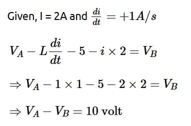
Q1: AB is a part of an electrical circuit (see figure). The potential difference "VA - VB", at the instant when current i = 2 A and is increasing at a rate of 1 amp/second is: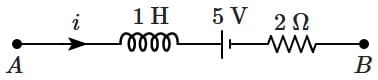
(a) 9 volts
(b) 10 volts
(c) 5 volts
(d) 6 volts
Ans: (b)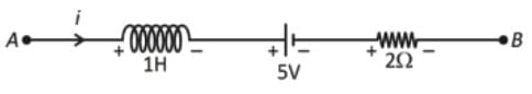
2024
Q1: In the below diagram, a strong bar magnet is moving towards solenoid-2 from solenoid-1. The direction of induced current in solenoid-1 and that in solenoid-2, respectively, are through the directions: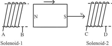 (a) AB and DC
(b) BA and CD
(c) AB and CD
(d) BA and DC (NEET 2024)
Ans: (a)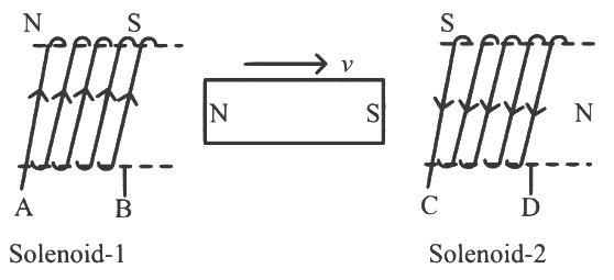 North of magnet is moving away from solenoid 1 so end B of solenoid 1 is South
and as south of magnet is approaching solenoid 2 so end C of solenoid 2 is South.
Q2: A sheet is placed on a horizontal surface in front of a strong magnetic pole. A force is needed to: (NEET 2024)
A. hold the sheet there if it is magnetic.
B. hold the sheet there if it is non-magnetic.
C. move the sheet away from the pole with uniform velocity if it is conducting.
D. move the sheet away from the pole with uniform velocity if it is both, non-conducting and non-polar.
Choose the correct statement(s) from the options given below:
(A) A and C only
(B) A, C, and D only
(C) C only
(D) B and D only
Ans: (a)
A. A force is needed to hold the sheet there if it is magnetic.
A magnetic sheet implies it is made of a ferromagnetic material (e.g., iron, nickel) that can be attracted to a magnet. If the sheet is ferromagnetic, it will experience an attractive force toward the magnetic pole due to the magnetic field gradient. To hold the sheet in place (prevent it from moving toward the pole), an external force must counteract this attraction.
Conclusion: This statement is correct. A force is needed to hold a magnetic sheet in place.
B. A force is needed to hold the sheet there if it is non-magnetic.
A non-magnetic sheet could mean it is neither ferromagnetic nor paramagnetic, typically implying it is a material like plastic, wood, or a diamagnetic substance that does not interact significantly with a magnetic field. In a static magnetic field, such a sheet experiences no magnetic force (diamagnetic effects are extremely weak and negligible for holding purposes). Thus, no force is needed to hold a non-magnetic sheet in place.
Conclusion: This statement is incorrect. No force is needed to hold a non-magnetic sheet.
C. A force is needed to move the sheet away from the pole with uniform velocity if it is conducting.
A conducting sheet (e.g., made of copper or aluminum) can interact with a magnetic field if it is moved, due to electromagnetic induction. If the sheet is moved away from the magnetic pole with uniform velocity, the magnetic flux through the sheet changes (assuming a non-uniform field, common near a pole). This induces eddy currents in the conducting sheet, which, according to Lenz's law, produce a magnetic field opposing the change in flux. This results in a drag force opposing the motion.
To maintain uniform velocity (constant speed, zero acceleration), a force must be applied to counteract this drag force. The drag force arises because the induced currents interact with the external magnetic field, creating a force that resists the motion.
Conclusion: This statement is correct. A force is needed to move a conducting sheet away from the pole with uniform velocity due to induced eddy currents.
D. A force is needed to move the sheet away from the pole with uniform velocity if it is both non-conducting and non-polar.
A sheet that is non-conducting (e.g., an insulator like plastic or glass) does not allow current flow, so no eddy currents are induced when it is moved in a magnetic field. Non-polar is less standard in magnetism but likely means non-magnetic (neither ferromagnetic nor paramagnetic) and not polarized in an electrostatic sense (irrelevant here, as the problem involves a magnetic field, not an electric field). Thus, the sheet does not interact with the static magnetic field.
Moving such a sheet away from the pole with uniform velocity requires no force to counteract magnetic effects, as there is no magnetic interaction (no attraction, repulsion, or induced forces). The only force needed would be to overcome friction or inertia, but the problem implies the force is related to the magnetic context, not mechanical resistances.
Conclusion: This statement is incorrect. No magnetic-related force is needed to move a non-conducting, non-magnetic sheet with uniform velocity.
Thus, only A and C are correct.
Final Answer: (A) A and C only
Q3: An ideal inductor-resistor-battery circuit is switched on at t = 0 s. At time t, the current is i = i₀ (1 - e(-t/τ)) A, where i₀ is the steady-state value. The time at which the current becomes 0.5 i₀ is: [Given ln(2) = 0.693] (NEET 2024)
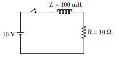 (a) 6.93 × 10³ s
(b) 6.93 ms
(c) 69.3 s
(d) 6.93 s
Ans: (b)
Given Data:
- Inductor (L) = 100 mH = 0.1 H
- Resistance (R) = 10 Ω
- Battery voltage = 10 V
- At time t, i(t) = 0.5 i₀
- ln(2) = 0.693
Step 1: Find the time constant (τ)
The time constant τ is given by:
τ = L / R
Substitute the values:
τ = 0.1 / 10 = 0.01 s
Step 2: Use the equation for current to find time when i(t) = 0.5 i₀
The current equation is:
i(t) = i₀ (1 - e(-t/τ))
When i(t) = 0.5 i₀, substitute this into the equation:
0.5 i₀ = i₀ (1 - e(-t/τ))
Cancel i₀ from both sides:
0.5 = 1 - e(-t/τ)
Rearranging:
e(-t/τ) = 0.5
Taking the natural logarithm on both sides:
-t/τ = ln(0.5)
-t/τ = -0.693
t = 0.693 × τ
Substitute τ = 0.01 s:
t = 0.693 × 0.01 = 6.93 × 10⁻³ s = 6.93 ms
Conclusion: The time at which the current becomes 0.5 i₀ is 6.93 ms.
Correct Answer: (b) 6.93 ms.
Q4: A conducting circular loop of face area 2.5 × 10⁻³ m² is placed perpendicular to a magnetic field which varies as B = 0.5 sin(100πt) T. The magnitude of induced EMF at time t = 0 s is: (NEET 2024)
(b) 125π mV
(c) 125π V
(d) 12.5π mV
Ans: (b)
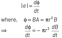
The induced EMF in a conducting loop is given by Faraday's Law of Induction:
ε = - dΦB / dt
Where:
- ΦB is the magnetic flux through the loop,
- B is the magnetic field,
- A is the area of the loop,
- t is time.
The magnetic flux ΦB is given by:
ΦB = B A
Since the loop is perpendicular to the magnetic field, the angle between the area vector and the magnetic field is 0 degrees, so:
ΦB = B A
Now, the magnetic field varies as:
B = 0.5 sin(100πt) T
The area of the loop is given as 2.5 × 10⁻³ m², so the magnetic flux at time t is:
ΦB = (0.5 sin(100πt)) (2.5 × 10⁻³)
ΦB = 1.25 × 10⁻³ sin(100πt) Weber
To find the induced EMF, we differentiate the flux with respect to time:
ε = - d / dt (1.25 × 10⁻³ sin(100πt))
ε = - 1.25 × 10⁻³ 100π cos(100πt)
At t = 0 s, cos(100πt) = 1, so:
ε = - 1.25 × 10⁻³ 100π
ε = - 0.125π V
Since we are asked for the magnitude:
ε = 0.125π V = 125π mV
Correct Answer: (b) 125π mV.
Q5: A rod of length L rotates with a small uniform angular velocity ω about its perpendicular bisector. A uniform magnetic field B exists parallel to the axis of rotation. The potential difference between the centre of the rod and an end is: (NEET 2024)
(a) BωL² / 8
(b) BωL² / 2
(c) BωL² / 4
(d) zero
Ans: (a)
Given:
- Length of the rod = L
- Angular velocity = ω
- Magnetic field B is parallel to the axis of rotation.
- The rod rotates about its perpendicular bisector.
When a rod rotates in a magnetic field, a potential difference (also known as an electromotive force or EMF) is induced due to the motion of the charges in the rod within the magnetic field. This phenomenon is explained by Faraday's law of induction.
The formula for induced EMF in a rotating rod is given by:
ε = B ω r² / 2
Where:
- B is the magnetic field strength,
- ω is the angular velocity,
- r is the distance from the center of the rod to the point where we measure the potential difference.
For a rod of length L rotating about its perpendicular bisector:
The distance from the center of the rod to its end is L/2.
Thus, the potential difference V between the center of the rod and one of its ends is:
V = (B ω (L/2)²) / 2
Simplifying: V = B ω L² / 8
Correct Answer: (a) BωL² / 8.
Q6: Let us consider two solenoids A and B, made from the same magnetic material of relative permeability μᵣ and of equal area of cross-section. The length of A is twice that of B, and the number of turns per unit length in A is half that of B. The ratio of self-inductances of the two solenoids, LA : LB is: (NEET 2024)
(a) 1 : 2
(b) 2 : 1
(c) 8 : 1
(d) 1 : 8
Ans: (a)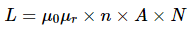
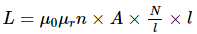
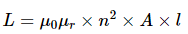
⇒ L ∝ n2l
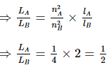
= 1 : 2
2023
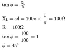
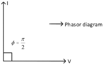
Q1: An ac source is connected in the given circuit. The value of 0 will be : (NEET 2023)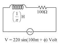 (a) 60o
(b) 90o
(c) 30o
(d) 45o
Ans: (d)
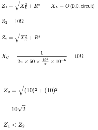
Q2: If Z1 and Z2 are the impedances of the given circuits (a) and (b) as shown in figures, then choose the correct option (NEET 2023)

(a) Z1 < Z2
(b) Z1 + Z2 = 20 Ω
(c) Z1 = Z2
(d) Z1 >Z2
Ans: (a)
Q3: The maximum power is dissipated for an ac in a/an: (NEET 2023)
(a) resistive circuit
(b) LC circuit
(c) inductive circuit
(d) capacitive circuit
Ans: (a)
Power dissipated is maximum of purely resistive circuit.
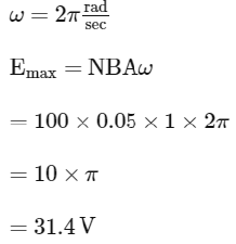
Q4: An emf is generated by an ac generator having 100 turn coil, of loop area 1 m2. The coil rotates at a speed of one revolution per second and placed in a uniform magnetic field of 0.05 T perpendicular to the axis of rotation of the coil. The maximum value of emf is :- (NEET 2023)
(a) 3.14 V
(b) 31.4 V
(c) 62.8 V
(d) 6.28 V
Ans: (b)
Q5: For very high frequencies, the effective impedance of the circuit (shown in the figure) will be:- (NEET 2023)
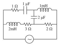 (a) 4 Ω
(b) 6 Ω
(c) 1 Ω
(d) 3 Ω
Ans: (d)
As frequency is very high
XC ≈ 0
XL → α
Effective circuit will be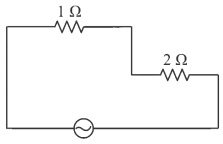
Effective impedance of circuit will be = 3Ω
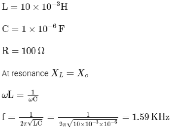
Q6: In a series LCR circuit, the inductance L is 10 mH, capacitance C is 1 μF and resistance R is 100Ω. The frequency at which resonance occurs is (NEET 2023)
(a) 15.9 kHz
(b) 1.59 rad/s
(c) 1.59 kHz
(d) 15.9 rad/s
Ans: (c)
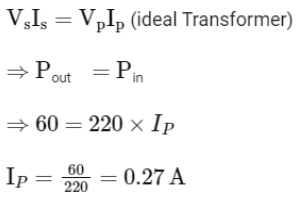
Q7: A 12 V,60 W lamp is connected to the secondary of a step down transformer, whose primary is connected to ac mains of 220 V. Assuming the transformer to be ideal, what is the current in the primary winding ? (NEET 2023)
(a) 2.7 A
(b) 3.7 A
(c) 0.37 A
(d) 0.27 A
Ans: (d)
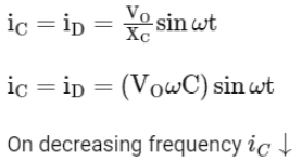
Q8: An ac source is connected to a capacitor C. Due to decrease in its operating frequency (NEET 2023)
(a) displacement current increases.
(b) displacement current decreases.
(c) capacitive reactance remains constant.
(d) capacitive reactance decreases.
Ans: (b)
Q9: The magnetic energy stored in an inductor of inductance 4 μH carrying a current of 2 A is (NEET 2023)
(a) 4 μJ
(b) 4 mJ
(c) 8 mJ
(d) 8 μJ
Ans: (d)
Solution: Magnetic energy stored in an inductor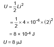
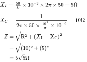
Q10: The net impedance of circuit (as shown in figure) will be: (NEET 2023)
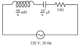
(a) 15 Ω
(b) 5√5 Ω
(c) 25 Ω
(d) 10√2 Ω
Ans: (b)
2022
Q2: Given below are two statements
Statement I : In an a.c circuit, the current through a capacitor leads the voltage across it.
Statement II : In a.c circuit containing pure capacitance only, the phase difference between the current and voltage is π.
In the light of the above statements, choose the most appropriate answer from the options given below:
(a) Statement I is incorrect but Statement II is correct
(b) Both Statement I and Statement II are correct
(c) Both Statement I and Statement II are incorrect
(d) Statement I is correct but Statement II is incorrect
Ans: (d)
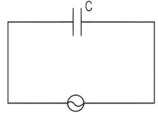

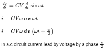
Thus statement I is correct while II is incorrect.
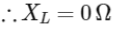
Q3: An inductor of inductance 2 mH is connected to a 220 V, 50 Hz ac source. Let the inductive reactance in the circuit is X1. If a 220 V dc source replace the ac source in the circuit, then the inductive reactance in the circuit is X2, X1 and X2 respectively are :
(a) 0.628 Ω, infinity
(b) 6.28 Ω, zero
(c) 6.28 Ω, infinity
(d) 0.628 Ω, zero
Ans: (d)
We know, for A.C. Source
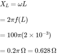
For D.C. Source
The inductor behaves as a closed circuit offering no resistance at all (at steady state) as w = 0 (For D.C.)
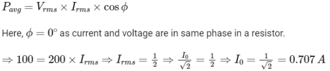
Q4: A standard filament lamp consumes 100 W when connected to 200 V ac mains supply. The peak current through the bulb will be :
(a) 2 A
(b) 0.707 A
(c) 1 A
(d) 1.414 A
Ans: (b)
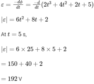
Q5: The magnetic flux linked to a circular coil of radius R is.
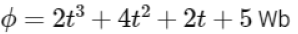
The magnitude of induced emf in the coil at t = 5 s is
(a) 192 V
(b) 108 V
(c)197 V
(d) 150 V
Ans: (a)
Given magnetic flux is

Induced emf is given by
Q6: The peak voltage of the ac source is equal to
(a) The value of voltage supplied to the circuit
(b) The rms value of the ac source
(c) √2 times the rms value of the ac source
(d) 1/√2 times the rms value of the ac source
Ans: (c)
We know,
RMS value of A.C. 
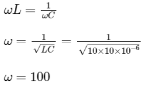
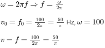
Q8: A series LCR circuit with inductance 10 H, capacitance 10 μF, resistance 50 Ω is connected to an ac source of voltage, V = 200sin(100t) volt. If the resonant frequency of the LCR circuit is v0 and the frequency of the ac source is v, then
(a) 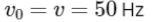
(b) 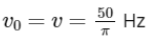
(c) 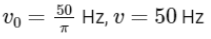
(d) 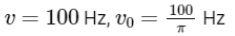
Ans: (b)
Q9: A big circular coil of 1000 turns and an average radius of 10 m is rotating about its horizontal diameter at 2 rad s-1 . If the vertical component of the earth's magnetic field at that place is 2 × 10⁻⁵ T and the electrical resistance of the coil is 12.56 ohm, then the maximum induced current in the coil will be
(a) 1.5 A
(b) 1 A
(c) 2 A
(d) 0.25 A
Ans: (b)
Solution: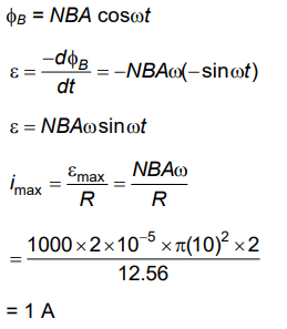
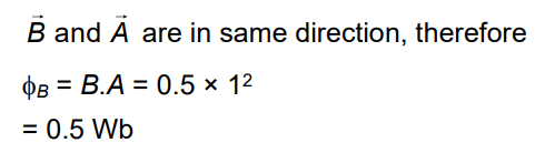
Q10: A square loop of side 1 m and resistance 1Ω is placed in a magnetic field of 0.5 T. If the plane of the loop is perpendicular to the direction of the magnetic field, the magnetic flux through the loop is
(a) 0.5 weber
(b) 1 Weber
(c) Zero Weber
(d) 2 Weber
Ans: (a)
Solution: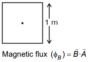
2021
Q1: Two conducting circular loops of radii R1 and R2 are placed in the same plane with their centres coinciding. If R1 >> R2, the mutual inductance M between them will be directly proportional to
(a) R1/R2
(b) R2/R1
(c) R12/R2
(d) R22/R1
Ans: (d)
Solution:
The magnetic field at the centre of the primary coil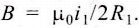 Considering it to be uniform, magnetic flux passing through the secondary coil is
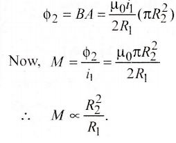
2020
Q1: The magnetic flux linked with a coil (in Wb) is given by the equation φ = 5t2 + 3t + 16 The magnitude of induced emf in the coil at the fourth second will be
(a) 33 V
(b) 43 V
(c) 108 V
(d) 10 V
Ans: (b)
We are given the magnetic flux:
φ = 5t² + 3t + 16
To find the induced emf (e), we use Faraday's Law:
e = dφ/dt
Differentiate φ with respect to t:
dφ/dt = d/dt (5t² + 3t + 16) = 10t + 3
Now plug in t = 4 seconds:
e = 10(4) + 3 = 40 + 3 = 43 V
Q2: A wheel with 20 metallic spokes each 1 m long is rotated with a speed of 120 rpm in a plane perpendicular to a magnetic field of 0.4 G. The induced emf between the axle and rim of the wheel will be (1 G = 10-4 T)
(a) 2.51 × 10⁻⁴ V
(b) 2.51 × 10⁻⁵ V
(c) 4.0 × 10⁻⁵ V
(d) 2.51 V
Ans: (a)
Given, magnetic field,
B = 0.4 G = 0.4 × 10 - 4T
l = 1m
Frequency, f = 12 rpm = 120 / 60 rps = 2 Hz
Induced emf between the axle and rim of the wheel is given as
Q3: A light bulb and an inductor coil are connected to AC ac source through a key as shown in the figure below. The key is closed and after sometime an iron rod is inserted into the interior of the inductor. The glow of the light bulb
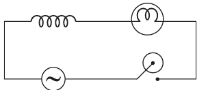 (a) decreases
(b) remains unchanged
(c) will fluctuate
(d) increases
Ans: (a)
When an iron rod is inserted into the interior of the inductor, then inductance (L) of the coil increases.
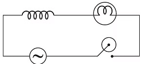
Hence, inductive reactance (XL = ωL)also increases.
∴ Current in the circuit is given as

Hence, when XL increases, then current I decreases. Therefore, glow of the light bulb will decrease.
2019
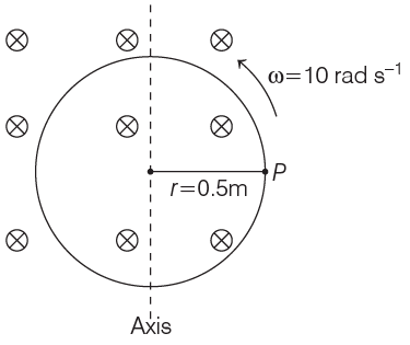
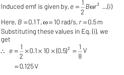
Q1: A cycle wheel of radius 0.5 m is rotated with constant angular velocity of 10 rad/s in a region of magnetic field of 0.1 T which is perpendicular to the plane of the wheel. The EMF generated between its centre and the rim is
(a) 0.25 V
(b) 0.125 V
(c) 0.5 V
(d) zero
Ans: (b)
When a conducting disc or wheel of radius r rotates with constant angular velocity of ω about its axis in a uniform magnetic field perpendicular to its plane and parallel to its axis of rotation, then,
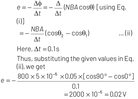
Q2: A coil of 800 turns effective area 0.05 m 2 is kept perpendicular to a magnetic field 5 × 10⁻⁵ T. When the plane of the coil is rotated by 90º around any of its co-planar axis in 0.1 s, the emf induced in the coil will be
(a) 0.2 V
(b) 2 ×10⁻³ V
(c) 0.02 V
(d) 2 V
Ans: (c)
Given,
area of coil, A = 0.05 m2
magnetic field, B = 5 × 10 -5 T and
number of turns, N = 800 .
The magnetic flux linked with the coil is
φ = N (B ⋅ A) = N BA cosθ ... (i)
where, θ is the angle between B and A.
The emf induced when coil is rotated from θ1 = 0° to θ2 = 90° is
Q4: In which of the following devices, the eddy current effect is not used?
(a) Induction furnace
(b) Magnetic braking in train
(c) Electromagnet
(d) Electric heater
Ans: (d)
Solution:
A. Induction Furnace: Eddy currents are used in induction furnaces to heat metal for melting or heating purposes. The metal is placed inside a coil, and alternating current passes through the coil, inducing eddy currents in the metal, which heats it up due to its electrical resistance.
B. Magnetic Braking in Train: Eddy currents are used in magnetic braking systems in trains. When a train's metal wheels pass through a magnetic field, eddy currents are induced in the wheels, creating a force that opposes the motion of the train, slowing it down.
C. Electromagnet: Eddy currents can have an undesirable effect on electromagnets because they can cause energy loss and heating. However, in devices like transformers and electric motors, eddy currents can be minimized by using laminated cores or by using materials with high electrical resistivity.
D. Electric Heater: Electric heaters typically do not use the eddy current effect. Instead, they use the resistance of a material to convert electrical energy into heat. The electric current passes through a resistive element, such as a wire or a coil, which heats up and transfers heat to the surrounding area.
2018
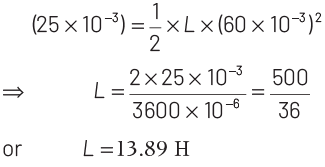
Q1: The magnetic potential energy stored in a certain inductor is 25 mJ, when the current in the inductor is 60 mA.
This inductor is of inductance
(a) 1.389 H
(b) 138.88 H
(c) 0.138 H
(d) 13.89 H
Ans: (d)
Given, magnetic potential energy stored in an inductor,
U = 25 mJ = 25 × 10 -3 J
Current in an inductor, I0 = 60 mA = 60 × 10-3 A
As, the expression for energy stored in an inductor is given as

where, L is the inductance of the inductor.
Substituting the given values in above equation., we get
2017
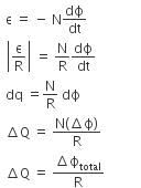
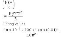
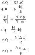
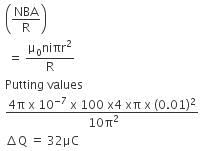
Q1: A long solenoid of diameter 0.1 m has 2 × 10⁴ turns per meter. At the centre of the solenoid, a coil of 100 turns and a radius of 0.01 m is placed with its axis coinciding with the solenoid axis. The current in the solenoid reduces at a constant rate to 0 A from 4 A in 0.05 s. If the resistance of the coil is 10π2Ω. The total charge flowing through the coil during this time is:(a) 16 μC
(b) 32 μC
(c) 16 π μC
(d) 32 π μC
Ans: (b)
Solution:
2016
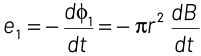
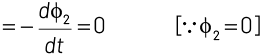
Q1: A uniform magnetic field is restricted within a region of radius r. The magnetic field changes with time at a rate dB/dT. Loop 1 of radius R > r encloses the region r and loop 2 of radius R is outside the region of magnetic field as shown in the figure. Then, the emf generated is
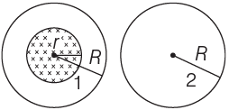
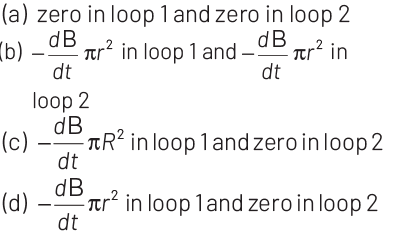
Ans: (c)
Induced emf in the region is given by
Rate of change of magnetic flux associated with loop 1
Similarly e2 = emf associated with loop 2
Q2: A long solenoid has 1000 turns. When a current of 4A flows through it, the magnetic flux linked with each turn of the solenoid is 4 x 10⁻³ Wb. The self-inductance of the solenoid is
(a) 1H
(b) 4H
(c) 3H
(d) 2H
Ans: (a)
Solution:
Given,
Number of turns in the solenoid, N = 1000
Current, I = 4 A
Magnetic flux, straight phi subscript straight B = 4 x 10⁻³ Wb
Self-inductance of the solenoid is given by,
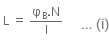
Putting the value of the equation in (i), we get
= 1H
2015
Q1: An electron moves on a straight line path XY as shown. The abcd is a coil adjacent in the path of electron. What will be the direction of current, if any induced in the coil?
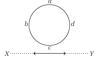
(a) abcd
(b) adcb
(c) The current will reverse its direction as the electron goes past the coil
(d) No current induced
Ans: (c)
When the electron moves from X to X, the flux linked with the coil abed (which is into the page) will first increase and then decrease as the electron passes by. So the induced current in the coil will be first anticlockwise and will reverse its direction (i.e. will become clockwise) as the electron goes past the coil.
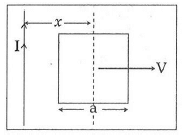
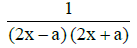
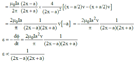
Q2: A conducting square frame of side 'a' and a long straight wire carrying current I are located in the same plane as shown in the figure. The frame moves to the right with a constant velocity 'V'. The emf induced in the frame will be proportional to :
(a)
(b)

(c)

(d)

Ans: (a)
Solution:
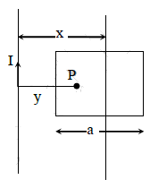
See figure alongside.
Let x be the distance of the centre of the frame from the long straight wire carrying current I.
Consider the point P at a distance y from the long straight wire carrying current I.
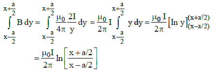
The strength of magnetic induction at point P is given by

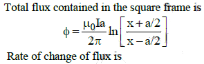
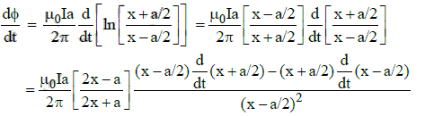
Integrating over y from y = (x - a/2) to y = (x + a/2)
We get
2014
Q1: A thin semicircular conducting ring (PQR) of radius 'r' is falling with its plane vertical in a horizontal magnetic field B, as shown in figure. The potential difference developed across the ring when its speed is v, is : 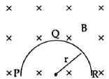
(a) πrBv and R is at higher potential
(b) 2rBv and R is at higher potential
(c) Zero
(d) Bvπr2/2 & P is at a higher potential
Ans: (b)
Solution:
Effective length = 2r
Potential developed = 2rBv
FAQs on NEET Previous Year Questions (2014-2025): Electromagnetic Induction
| 1. Which electromagnetic induction concepts appear most often in NEET exams from 2014 to 2025? |  |
| 2. How do I identify whether a NEET problem involves self-inductance or mutual inductance? | |
| 3. What's the most common mistake students make when applying Lenz's law to NEET electromagnetic induction problems? | |
| 4. Why do transformer problems in NEET always involve the turns ratio and power loss calculations? | |
| 5. How should I approach understanding motional EMF and its relationship to Faraday's law for NEET success? | |


