NEET Previous Year Questions (2014-2025): Alternating Current


2025
Q1: To an AC power supply of 220 V at 50 Hz, a resistor of 20 Ω, a capacitor of reactance 25 Ω and an inductor of reactance 45 Ω are connected in series. The corresponding current in the circuit and the phase angle between the current and the voltage is, respectively: [2025]
(a) 15.6 A and 30°
(b) 15.6 A and 45°
(c) 7.8 A and 30°
(d) 7.8 A and 45°
Ans: (d)
XL = 45 W, XC = 25 W, R = 20 W
⇒ I = 220 / √((XL - XC)2 + R2) = 220 / √((45 - 25)2 + 202)
⇒ = 220 / (2√2) = 11 / √2 = 7.779 A
⇒ tan φ = (XL - XC) / R = (45 - 25) / 20 = 1
⇒ φ = 45°
2024
Q1: In an ideal transformer, the turns ratio is NP / NS = 1/2. The ratio VS : VP is equal to (the symbols carry their usual meaning) :(a) 1 : 2
(b) 2 : 1
(c) 1 : 1
(d) 1 : 4 [2024]
Ans: (b)
An ideal transformer is a device that transfers electrical energy from one circuit to another through inductively coupled conductors-the transformer's coils. The primary coil (with NP turns) is connected to the input voltage (VP), and the secondary coil (with NS turns) delivers the output voltage (VS).
The relationship between the input (primary) voltage and output (secondary) voltage in a transformer is determined by the ratio of the number of turns in the primary coil to the number of turns in the secondary coil, expressed by the formula:

In this case, the given turns ratio is NP / NS = 1 / 2. To find the correct expression for VS / VP, we need to invert the given ratio to reflect the relationship with respect to the voltages. This means:

Therefore, substituting into the voltage ratio equation:

This indicates that the secondary voltage (VS) is twice the primary voltage (VP). If we were to express the ratio VS : VP based on this, it would be: Option B 2 : 1
This is the correct answer as it represents that, in accordance with the transformer's turns ratio, the voltage in the secondary coil is twice that in the primary coil.
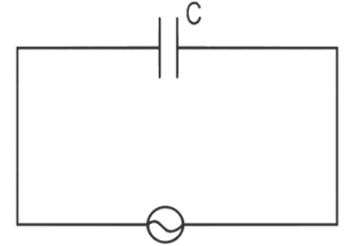
Q2: A 10μF capacitor is connected to a 210V, 50 Hz source as shown in figure. The peak current in the circuit is nearly (π=3.14) :
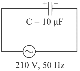 (a) 0.58 A
(b) 0.93 A
(c) 1.20 A
(d) 0.35 A [2024]
Ans: (b)
Capacitive Reactance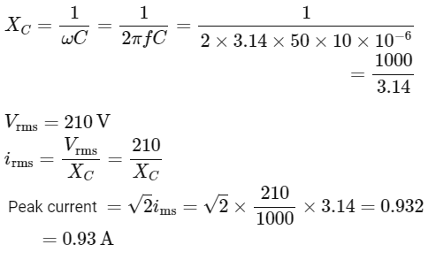
2023
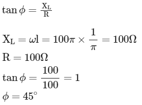
Q1: An ac source is connected in the given circuit. The value of
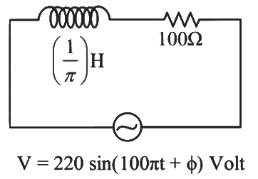
(a) 60o
(b) 90o
(c) 30o
(d) 45o
Ans: (d)
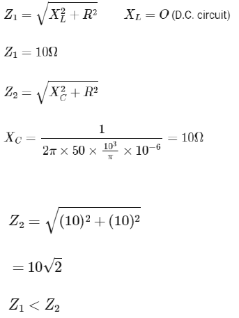
Q2: If Z1 and Z2 are the impedances of the given circuits (a) and (b) as shown in figures, then choose the correct option

(a) Z1 < Z2
(b) Z1 + Z2 = 20 Ω
(c) Z1 = Z2
(d) Z1 >Z2
Ans: (a)
Q3: The maximum power is dissipated for an ac in a/an:
(a) resistive circuit
(b) LC circuit
(c) inductive circuit
(d) capacitive circuit
Ans: (a)
Power dissipated is maximum of purely resistive circuit.
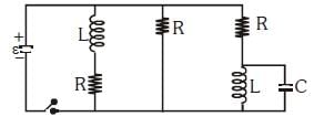
Q4: For very high frequencies, the effective impedance of the circuit (shown in the figure) will be:-
 (a) 4 Ω
(b) 6 Ω
(c) 1 Ω
(d) 3 Ω
Ans: (d)
As frequency is very high
XC ≈ 0
XL → α
Effective circuit will be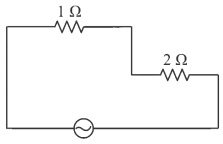
Effective impedance of circuit will be = 3Ω
Q5: The magnetic energy stored in an inductor of inductance 4 μH carrying a current of 2 A is :
(a) 4 mJ
(b) 8 mJ
(c) 8 μJ
(d) 4 μJ
Ans: (c)
The formula for calculating the magnetic energy stored in an inductor is given by:
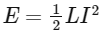
where:
E is the energy stored (in joules, J),
L is the inductance of the inductor (in henrys, H),
I is the current flowing through the inductor (in amperes, A).
Plugging the given values into the formula:
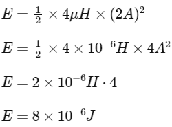
Hence, the energy stored in the inductor is 8 μJ.
Q6: In a series LCR circuit, the inductance L is 10 mH, capacitance C is 1 μF, and resistance R is 100 Ω. The frequency at which resonance occurs is
(a) 15.9 rad/s
(b) 15.9 kHz
(c) 1.59 rad/s
(d) 1.59 kHz
Ans: (d)
Solution: 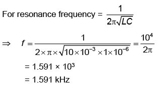
Q7: A 12 V, 60 W lamp is connected to the secondary of a step-down transformer, whose primary is connected to AC mains of 220 V. Assuming the transformer to be ideal, what is the current in the primary winding?
(a) 0.27 A
(b) 2.7 A
(c) 3.7 A
(d) 0.37 A
Ans: (a)
Solution: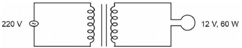
For ideal transformer
Pinput = Poutput
(VI)in = 60
220 × I = 60
I = 0.27 A
Q8: An AC source is connected to a capacitor C. Due to a decrease in its operating frequency
(a) Capacitive reactance decreases
(b) Displacement current increases
(c) Displacement current decreases
(d) Capacitive reactance remains constant
Ans: (c)
Solution: 
Since ω decreasing XC will increase hence current will decrease. Also conduction current = displacement current.
Therefore displacement current will decrease.
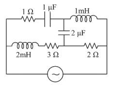
Q9: The net impedance of the circuit (as shown in the figure) will be 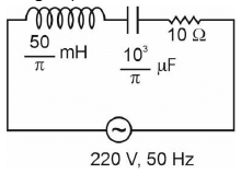 (a) 10√2 Ω
(b) 15 Ω
(c) 5√5
(d) 25 Ω
Ans: (c)
Solution: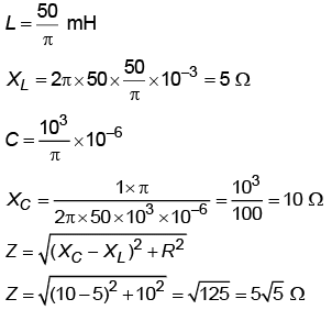
2022
Q1: Given below are two statements
Statement I : In an a.c circuit, the current through a capacitor leads the voltage across it.
Statement II : In a.c circuit containing pure capacitance only, the phase difference between the current and voltage is π.
In the light of the above statements, choose the most appropriate answer from the options given below:
(a) Statement I is incorrect but Statement II is correct
(b) Both Statement I and Statement II are correct
(c) Both Statement I and Statement II are incorrect
(d) Statement I is correct but Statement II is incorrect
Ans: (d)

Thus statement I is correct while II is incorrect.
Q2: An inductor of inductance 2 mH is connected to a 220 V, 50 Hz ac source. Let the inductive reactance in the circuit is X1. If a 220 V dc source replace the ac source in the circuit, then the inductive reactance in the circuit is X2, X1 and X2 respectively are :
(a) 0.628 Ω, infinity
(b) 6.28 Ω, zero
(c) 6.28 Ω, infinity
(d) 0.628 Ω, zero
Ans: (d)
We know, for A.C. Source
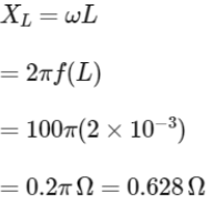
For D.C. Source
The inductor behaves as a closed circuit offering no resistance at all (at steady state) as w = 0 (For D.C.)
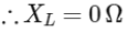
Q3: A standard filament lamp consumes 100 W when connected to 200 V ac mains supply. The peak current through the bulb will be :
(a) 2 A
(b) 0.707 A
(c) 1 A
(d) 1.414 A
Ans: (b)
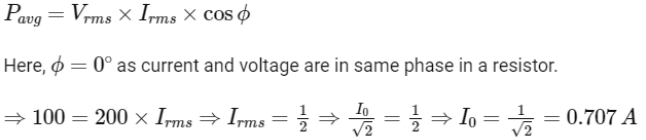
Q4: A series LCR circuit with inductance 10 H, capacitance 10 µF, and resistance 50 Ω is connected to an AC source of voltage, V = 200sin(100t) volt. If the resonant frequency of the LCR circuit is νo and the frequency of the AC source is ν, then
(a)
(b) 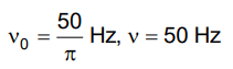
(c) 
(d) 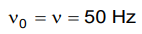
Ans: (a)
Solution: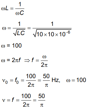
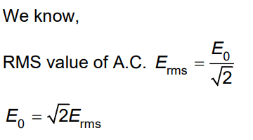
Q5: The peak voltage of the AC source is equal to
(a) The rms value of the AC source
(b) √2 times the rms value of the AC source
(c) 1/√2 times the rms value of the AC source
(d) The value of the voltage supplied to the circuit
Ans: (b)
Solution:
2021
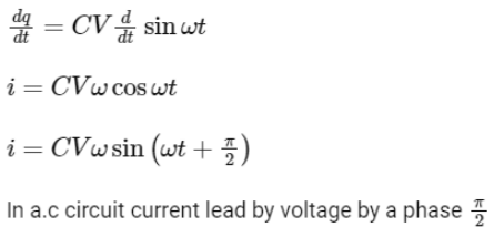
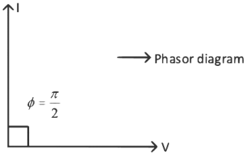
Q1: A capacitor of capacitance 'C', is connected across an ac source of voltage V, given by
V = V0sinωt
The displacement current between the plates of the capacitor, would then be given by :
(a) 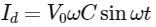
(b) 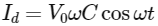
(c) 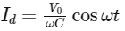
(d) 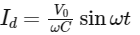
Ans: (b)
Given, V = V0sinωt
We know, q = CV
Now displacement current Id is given by,
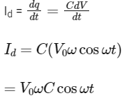
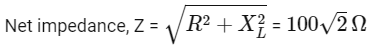
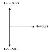
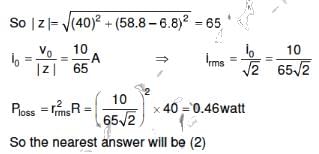
Q2: An inductor of inductance L, a capacitor of capacitance C, and a resistor of resistance 'R' are connected in series to an AC source of potential difference 'V' volts as shown in Fig. Potential difference across L, C, and R is 40 V, 10 V, and 40V, respectively. The amplitude of the current flowing through the LCR series circuit is 10√2A. The impedance of the circuit is:
(a) 4Ω
(b) 5Ω
(c) 4√2Ω
(d) 5√2Ω
Ans: (b)
Solution:
I0 = 10√2 A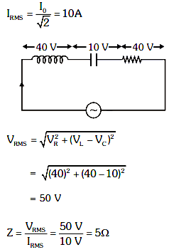
Q3: A step-down transformer connected to an AC mains supply of 220 V is made to operate at 11 V, 44 W lamp. Ignoring power losses in the transformer, what is the current in the primary circuit?
(a) 2 A
(b) 4 A
(c) 0.2 A
(d) 0.4 A
Ans: (c)
Solution:
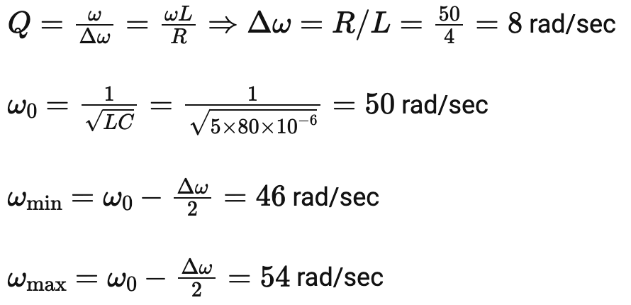
Q4: A series LCR circuit containing a 5.0 H inductor, 80 μF capacitor, and 40 Ω resistor is connected to a 230 V variable frequency AC source. The angular frequencies of the source at which power transferred to the circuit are half the power at the resonant angular frequency are likely to be
(a) 46 rad/s and 54 rad/s
(b) 42 rad/s and 58 rad/s
(c) 25 rad/s and 75 rad/s
(d) 50 rad/s and 25 rad/s
Ans: (a)
Solution:
 2020
2020
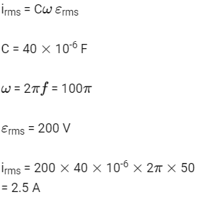
Q1: A 40 μF capacitor is connected to a 200 V. 50 Hz ac supply. The rms value of the current on the circuit is, nearly :
(a) 2.05 A
(b) 2.5 A
(c) 25.1 A
(d) 1.7 A
Ans: (b)
Q2: A series LCR circuit is connected to an AC voltage source. When L is removed from the circuit, the phase difference between current and voltage is π/3. If instead C is removed from the circuit, the phase difference is again π/3 between current and voltage. The power factor of the circuit is :
(a) 1.0
(b) -1.0
(c) Zero
(d) 0.5
Ans: (a)
Solution:
When the inductor alone is removed,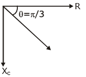
 When the capacitor alone is removed,
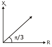
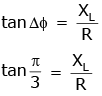 Thus, for the original circuit,
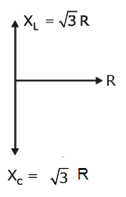
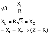 Power factor = cos Δϕ = R/Z = R/R = 1
2019
Q1: Which of the following acts as a circuit protection device?
(a) Conductor
(b) Inductor
(c) Switch
(d) Fuse
Ans: (d)
Solution:
Fuse wire has less melting point so when excess current flows, due to heat produced in it, it melts.
Q2: A parallel plate capacitor of capacitance 20 mF is being charged by a voltage source whose potential is changing at the rate of 3 V/s. The conduction current through the connecting wires, and the displacement current through the plates of the capacitor, would be, respectively.
(a) Zero, 60 μA
(b) 60 μA, 60 μA
(c) 60 μA, zero
(d) Zero, zero
Ans: (b)
Solution:
The capacitance of capacitor C = 20 mF
= 20 × 10-6 F
Rate of change of potential 
 ic = 20 × 10-6 × 3
= 60 × 10-6 A
= 60 μA
As we know id = ic = 60 mA
2018
Q1: The magnetic potential energy stored in a certain inductor is 25 mJ when the current in the inductor is 60 mA. This inductor is of inductance:
(a) 0.138 H
(b) 138.88 H
(c) 1.389 H
(d) 13.89 H
Ans: (d)
Solution:
Energy stored in the inductor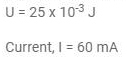 Energy stored in the inductor
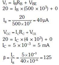
Q2: In the circuit shown in the figure, the input voltage Vi is 20 V, VBE = 0, and VCE = 0. The values of IB, IC, and β are given by: 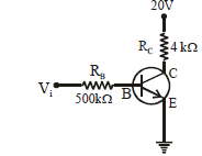
(a) IB = 40 µA, IC = 10 mA, β = 250
(b) IB = 25 µA, IC = 5 mA, β = 200
(c) IB = 20 µA, IC = 5 mA, β = 250
(d) IB = 40 µA, IC = 5 mA, β = 125
Ans: (d)
Solution:
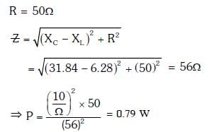
Q3: An inductor 20 mH, a capacitor 100 μF, and a resistor 50 Ω are connected in series across a source of emf, V = 10 sin 314 t. The power loss in the circuit is
(a) 0.79 W
(b) 0.43 W
(c) 2.74 W
(d) 1.13 W
Ans: (a)
Solution: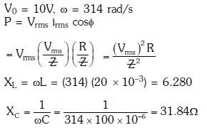
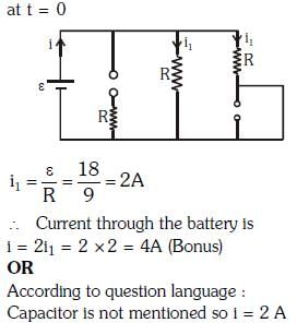
Q4: Figure shows a circuit that contains three identical resistors with resistance R = 9.0 Ω each, two identical inductors with inductance L = 2.0 m Heach, and an ideal battery with emf ε = 18 V. The current 'i' through the battery just after the switch closed is:
(a) 0.2 A
(b) 2 A
(c) 0 ampere
(d) 2 mA
Ans: (b)
Solution:
 2016
2016
Q1: Which of the following combinations should be selected for better tuning of an L-C-R circuit used for combination ?
(a) R = 20 Ω, L = 1.5 H, C = 35 μF
(b) R = 25 Ω, L = 2.5 H, C = 45 μF
(c) R = 15 Ω, L = 3.5 H, C = 30 μF
(d) R = 25 Ω, L = 1.5 H, C = 45 μF
Ans: (c)
Quality factor of an L-C-R circuit is given by,
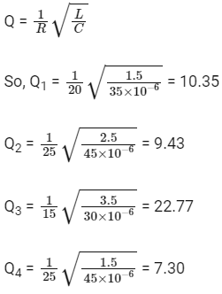
As Q3 is maximum of Q1, Q2, Q3, and Q4. Hence, option (c) should be selected for better tuning of an L-C-R circuit.
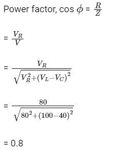
Q2: The potential differences across the resistance, capacitance and inductance are 80 V, 40 V and 100 V respectively in an L-C-R circuit. The power factor of this circuit is
(a) 0.4
(b) 0.5
(c) 0.8
(d) 1.0
Ans: (c)
Q3: A 100 Ω resistance and a capacitor of 100 Ω reactance are connected in series across a 220 V source. When the capacitor is 50% charged, the peak value of the displacement current is
(a) 2.2 A
(b) 11 A
(c) 4.4 A
(d) 11√2 A
Ans: (a)
Peak value of displacement current = Maximum conduction current in the circuit
Q4: An inductor of 20 mH, a capacitor of 50 μF and a resistor. 40Ω are connected in series across a source of emf V = 10 sin 340 t. The power loss in the A.C. circuit is
(a) 0.89W
(b) 0.51W
(c) 0.67W
(d) 0.76W
Ans: (b)
Solution:
Q5: A small signal voltage V(t) = V0 sinωt is applied across an ideal capacitor C :
(a) Current I(t), leads voltage V(t) by 180 degree
(b) Current I(t), lags voltage V(t) by 90 degree
(c) Over a full cycle the capacitor C does not consume any energy from the voltage source.
(d) Current I(t) is in phase with voltage V(t)
Ans: (c)
Solution:
A capacitor does not consume energy effectively over full cycles.
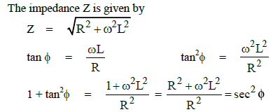
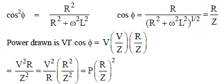
Q6: A resistance 'R' draws power 'P' when connected to an AC source. If an inductance is now placed in series with the resistance, such that the impedance of the circuit becomes 'Z', the power drawn will be :
(a) P
(b)

(c)

(d)

Ans: (b)
Solution:
A resistance R draws power P when connected to an AC source.
The magnitude of voltage of the AC source is
V2 = RP
∴ V= 
An inductor of inductance L and reactance ωL is now placed in series with the resistance
2015
Q1: A series R-C circuit is connected to an alternating voltage source. Consider two situations :
(a) When capacitor is air filled.
(b) When capacitor is mica filled.
Current through resistor is I and voltage across capacitor is V then
(a) ia > ib
(b) Va = Vb
(c) Va < Vb
(d) Va > Vb
Ans: (d)
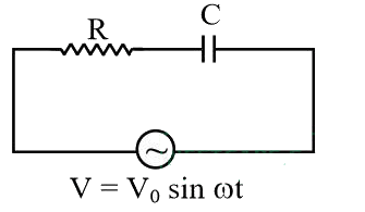
For series R - C circuit, capacitive reactance,
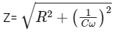
Current through resistor, i = Current in the circuit
When mica is introduced capacitance will increase, hence voltage across capacitor gets decrease.
2014
Q1: A transformer having an efficiency of 90% is working on 200 V and 3 kW power supply. If the current in the secondary coil is 6A, the voltage across the secondary coil and the current in the primary coil respectively are :
(a) 450 V, 13.5 A
(b) 600 V, 15 A
(c) 300 V, 15 A
(d) 450 V, 15 A
Ans: (d)
Solution:
Initial power = 3000 W
As the efficiency is 90%, then the final power
That is,
FAQs on NEET Previous Year Questions (2014-2025): Alternating Current
| 1. What are the main formulas I need to memorise for alternating current questions in NEET? |  |
| 2. How do I solve alternating current problems involving RLC circuits that appeared in previous NEET exams? | |
| 3. Why do we use RMS values instead of peak values when calculating AC power in alternating current circuits? | |
| 4. What's the difference between inductive reactance and capacitive reactance, and when does each dominate in AC circuits? | |
| 5. How should I approach alternating current NEET previous year questions to identify which concept is being tested? | |


