NCERT Exemplar: Wave Optics | Physics Class 12 - NEET PDF Download

MULTIPLE CHOICE QUESTIONS
Q.1. Consider a light beam incident from air to a glass slab at Brewster’s angle as shown in Fig.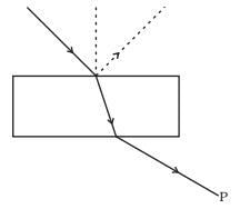 A polaroid is placed in the path of the emergent ray at point P and rotated about an axis passing through the centre and perpendicular to the plane of the polaroid.
(a) For a particular orientation there shall be darkness as observed through the polaoid.
(b) The intensity of light as seen through the polaroid shall be independent of the rotation.
(c) The intensity of light as seen through the Polaroid shall go through a minimum but not zero for two orientations of the polaroid.
(d) The intensity of light as seen through the polaroid shall go through a minimum for four orientations of the polaroid.
Ans. (c)
Solution.
Key concept:
Brewster’s law: Brewster discovered that when a beam of unpolarised light is reflected from a transparent medium (refractive index = µ), the reflected light is completely plane polarised at a certain angle of incidence (called the angle of polarisation θp).
From figure, it is clear that θp+ θr = 90°
Also n = tan θp (Brewster’s law)
(i) For i < θp or i > θp
Both reflected and refracted rays becomes partially polarised.
(ii) For glass θp = 51° for water θp = 53°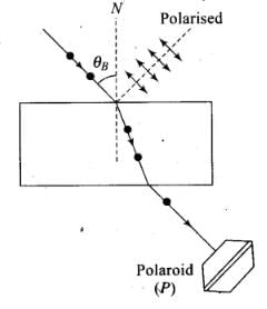 If a light beam is incident on a glass slab at Brewster’s angle, the transmitted beaiji is unpolarised and reflected beam is polarised.
In the given figure, the light beam is incident from air to the glass slab at Brewster’s angle (ip). The incident ray is unpolarised and is represented by dot (•). The reflected light is plane polarised represented by arrows.
As the emergent ray is unpolarised, hence intensity cannot be zero when passes through polaroid.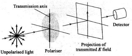
Important points:
light: The phenomenon of limiting the vibrating of electric field vector in one direction in a plane perpendicular to the direction of propagation of light wave is called polarization of light.
(i) The plane in which oscillation occurs in the polarised light is called plane of oscillation.
(ii) The plane perpendicular to the plane of oscillation is called plane of polarisation.
(iii) Light can be polarised by transmitting through certain crystals such as tourmaline or polaroids.
Polaroids: It is a device used to produce the plane polarised light. It is based on the principle of selective absorption and is more effective than the tourmaline crystal, or it is a thin film of ultramicroscopic crystals of quinine iodosulphate with their optic axis parallel to each other.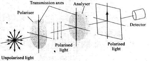 (A) Transmission axes of the polariser and analyser arc parallel to each other, so whole of the polarised light passes through analyser
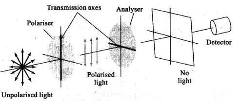 (B) Transmission axis of the analyser is perpendicular to the polariser. hence no light passes through the analyser
Q.2. Consider sunlight incident on a slit of width 104 Å. The image seen through the slit shall
(a) Be a fine sharp slit white in colour at the center.
(b) A bright slit white at the center diffusing to zero intensities at the edges.
(c) A bright slit white at the center diffusing to regions of different colours.
(d) Only be a diffused slit white in colour.
Ans. (a)
Solution.
Width of slit 104 Å = 10,000 Å.
Wavelength of visible light varies from 4000 to 8000 Å. As the width of slit 10000 Å is comparable to that of wavelength of visible light i.e. 8000 Å.
Hence the diffraction occurs with maxima at the centre. So at the centre all colours appear i.e. white colour at the centre appear.
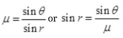
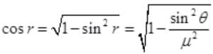
Q.3. Consider a ray of light incident from air onto a slab of glass (refractive index n) of width d, at an angle θ. The phase difference between the ray reflected by the top surface of the glass and the bottom surface is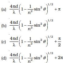
Ans. (a)
Solution.
Consider a ray of light ABCD through prism, and reflected rays BE and CF from incidence points B and C as shown in figure.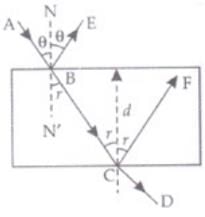 The time difference between two reflected ray BE and CF is equal to the time taken by ray to travel from B to C.
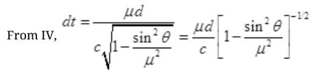
∴ Time difference dt between two reflected rays BE and CF are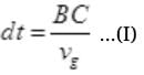

va = c
Substitute (II) and (III) in (I),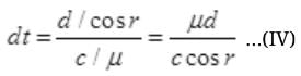
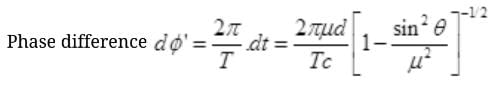
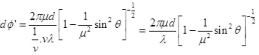
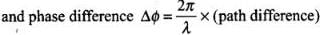
The phase diff. between ray AB and BC after refraction is π
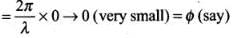
∴ Net phase difference = dϕ' + π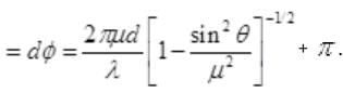
[it is very near to option (a).]
Q.4. In a Young’s double slit experiment, the source is white light. One of the holes is covered by a red filter and another by a blue filter.
In this case
(a) There shall be alternate interference patterns of red and blue.
(b) There shall be an interference pattern for red distinct from that for blue.
(c) There shall be no interference fringes.
(d) There shall be an interference pattern for red mixing with one for blue.
Ans. (c)
Solution.
For sustained interference, the source must be coherent and should emit the light of same frequency.
In this problem one hole is covered with red and other with blue, which has different frequency, so no interference takes place.
Q.5. Figure shows a standard two slit arrangement with slits S1, S2. P1, P2 are the two minima points on either side of P (Fig).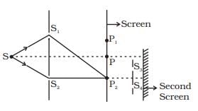 At P2 on the screen, there is a hole and behind P2 is a second 2- slit arrangement with slits S3, S4 and a second screen behind them.
(a) There would be no interference pattern on the second screen but it would be lighted.
(b) The second screen would be totally dark.
(c) There would be a single bright point on the second screen.
(d) There would be a regular two slit pattern on the second screen.
Ans. (d)
Solution.
At P2 is minima due to two wavefronts in opposite phase coming from, two slits
S1 and S2, but there is wavefronts from S1, S2 so P2 will act as a source of secondary wavelets. Wavefront starting from P2 reaches at S3 and S4 slits which will again acts as two monochromatic or coherent sources and will form pattern on second screen.
Q.6. Two source S1 and S2 of intensity I1 and I2 are placed in front of a screen [Fig.(a)]. The patteren of intensity distribution seen in the central portion is given by Fig.(b).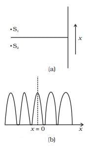 In this case which of the following statements are true.
(a) S1 and S2 have the same intensities.
(b) S1 and S2 have a constant phase difference.
(c) S1 and S2 have the same phase.
(d) S1 and S2 have the same wavelength.
Ans. (a), (b) and (c)
Solution.
(i) As the intensity at dark fringe is zero so intensities of S1 and S2 are equal.
(ii) As the graph of maxima and minima is symmetric. So the waves from S1 and S2 are at same phase difference or zero phase difference.
Q.7. Consider sunlight incident on a pinhole of width 103A. The image of the pinhole seen on a screen shall be
(a) A sharp white ring.
(b) Different from a geometrical image.
(c) A diffused central spot, white in colour.
(d) Diffused coloured region around a sharp central white spot
Ans. (b, d)
Solution.
The width of pinhole 103 Å = 1000 Å and wavelength of visible light is 4000 Å to 8000 Å i.e., size of slit less than (or comparable) with the wavelength of light.
So light from pinhole will diffract from the hole. Due to the diffraction pattern of fringes, the shape are quite different from hole.
Q.8. Consider the diffraction pattern for a small pinhole. As the size of the hole is increased
(a) The size decreases.
(b) The intensity increases.
(c) The size increases.
(d) The intensity decreases.
Ans. (a, b)
Solution.
We know that width (B0) of central maxima B0 = Dλ/d and width of nth secondary maxima = λ/d here distance (D) between slit and screen, wavelength λ of source does not change.
So on increasing width of hole of pinhole, ‘d’ increase. Hence the size of central maxima decreases verifies the option (a).
As the energy passing through hole increased on increasing the size of hole. So the intensity of pattern will increase. Hence verifies the option (b).
Q.9. For light diverging from a point source
(a) The wavefront is spherical.
(b) The intensity decreases in proportion to the distance squared.
(c) The wavefront is parabolic.
(d) The intensity at the wavefront does not depend on the distance.
Ans. (a, b)
Solution.
Light from point source emits in all around the source with same speed so forms a spherical surface of wavefront or spherical wavefront.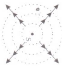 As the intensity (I) always decreases as the reciprocal of square of distance.
r = radius of spherical wavefront at any time (r = vt)
VERY SHORT ANSWER TYPE QUESTIONS
Q.10. Is Huygen’s principle valid for longitudunal sound waves?
Ans. Consider a source of sound formed with the compressions and rarefactions forward in all directions with same velocity. So longitudinal waves propagate with spherical symmetry in all directions as the wavefront in light waves. So Huygen’s principle is valid for longitudinal sound waves also.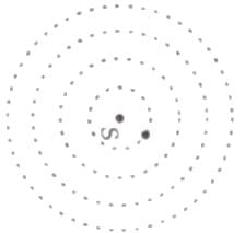 On a surface of sphere there will be either compression or rarefaction and that part can also behave like a source of sound but with low intensity.
Q.11. Consider a point at the focal point of a convergent lens. Another convergent lens of short focal length is placed on the other side. What is the nature of the wavefronts emerging from the final image?
Ans. Consider a point ‘F’ on focus of converging lens L1. The light rays from F, becomes parallel after refraction through L1. When these parallel rays falls on converging lens L2 placed co-axial on the other side of F of L1. L2 converges the rays at it’s focus at I. It now behave like a point source of rays and form a spherical wave front.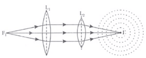
Q.12. What is the shape of the wavefront on earth for sunlight?
Ans. As the sun is very-very far from the earth so can be considered at infinity and sun can be considered as a point source which gives spherical wavefront. The size of the earth is very small as compared to distance of sun from earth and size of the sun so the plane wavefront reaches on earth as shown in figure here.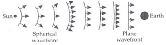
Q.13. Why is the diffraction of sound waves more evident in daily experience than that of light wave?
Ans. We know that frequencies of sound waves varies from 20 Hz to 20,000 Hz, so its corresponding wavelength varies from 15m to 15mm respectively. The size of slit (almost) becomes comparable to wavelength of sound so diffraction of sound wave takes place easily.
But the wavelength of visible light varies from 0.4 to 0.7 micron which is very small. So the size of most of the slits in not comparable with wavelength of visible light, due to this diffraction of light cannot take place.
Q.14. The human eye has an approximate angular resolution of φ = × 5.8 10-4 rad and a typical photo printer prints a minimum of 300 dpi (dots per inch, 1 inch = 2.54 cm). At what minimal distance z should a printed page be held so that one does not see the individual dots.
Ans. Angular separation =5.8 × 10⁻⁴ radian
The average distance between any two dots 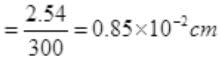
At the distance z cm, angle subtended 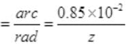
Resolution angle for human 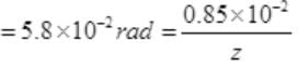
Maximum distance up to which human eye cannot see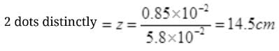
Which is less than distance of distinct vision.
So a normal person cannot see the dots.
Q.15. A polariod (I) is placed in front of a monochromatic source. Another polatiod (II) is placed in front of this polaroid (I) and rotated till no light passes. A third polaroid (III) is now placed in between (I) and (II). In this case, will light emerge from (II). Explain.
Ans. A polaroid (I) is placed in front of a monochromatic source. Another polariod (II) is placed in front of this polaroid (I) when the pass axis of (II) is parallel to (I), light passes through polaroid-II is unaffected.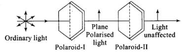 Now polariod (II) is rotated till no light passes. In this situation the pass axis of polariod (II) is perpendicular to polariod (I), then (I) and (II) are set in crossed positions. No light passes through polaroid-II.
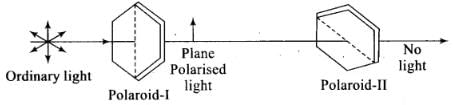 Now third polaroid (III) is now placed in between (I) and (II). Only in the special case s w hen the pass axis of (III) is parallel to (I) or (II) there shall be no light emerging. In all other cases there shall be light emerging because the pass axis of (II) is no longer perpendicular to the pass axis of (III).
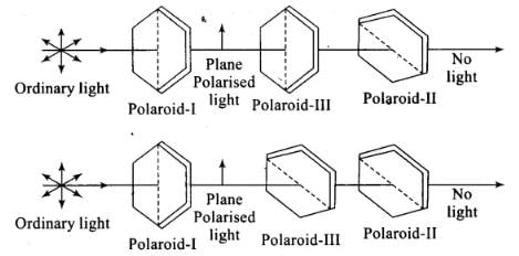 Now polariod (II) is rotated till no light passes. In this situation the pass axis of polariod (II) is perpendicular to polariod (I), then (I) and (II) are set in crossed positions. No light passes through polaroid-II.
Now third polaroid (III) is now placed in between (I) and (II). Only in the special cases when the pass axis of (III) is parallel to (I) or (II) there shall be no light emerging. In all other cases there shall be light emerging because the pass axis of (II) is no longer perpendicular to the pass axis of (III).
SHORT ANSWER TYPE QUESTIONS
Q.16. Can reflection result in plane polarised light if the light is incident on the interface from the side with higher refractive index?
Ans. If angle of incidence is equal to Brewster’s angle, the transmitted light is slightly polarised and reflected light is plane polarised.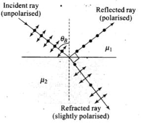 Polarisation by reflection occurs when the angle of incidence is the Brewster’s angle.
i.e., 
When the light rays travels in such a medium, the critical angle is
As |tan iB| > |sin iC| for large angles iB < iC.
Thus, the polarisation by reflection occurs definitely.
Important point: Brewster’s angle (also known as the polarization angle) is an angle of incidence at which light with a particular polarization is perfectly transmitted through a transparent dielectric surface, with no reflection. When unpolarized light is incidents this angle, the light that is reflected from the surface is therefore perfectly polarized. This special angle of incidence is named after the Scottish physicist Sir David Brewster.
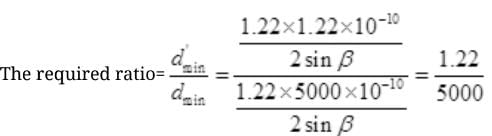
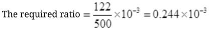
Q.17. For the same objective, find the ratio of the least separation between two points to be distinguished by a microscope for light of 5000 Å and electrons accelerated through 100V used as the illuminating substance.
Ans. λ = 5000 Å = 5000×10-10m
In microscope, 
Limit of resolution by light of 5000 Å
dmin =  or dmin =
The de Broglie wavelength λd of illuminated light = 

The limit of resolution by 100 V light d'min = 
d'min = 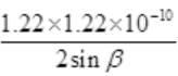
Q.18. Consider a two slit interference arrangements (Fig.) such that the distance of the screen from the slits is half the distance between the slits. Obtain the value of D in terms of λ such that the first minima on the screen falls at a distance D from the centre O.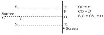 Ans. According to θ,
x = D (Given) ....(I)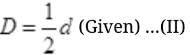
d = 2D
Path difference at P = S2 P-S1 P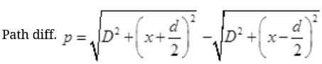
Substitute the value of d and x from I and II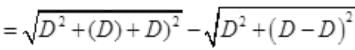
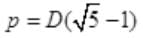
The path difference for nth dark fringe from central maxima ‘O’ is 
∴ For Ist minima p = λ/2
Put the value of p in (III)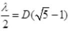
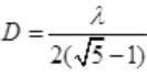
Rationalising the denominator, we get,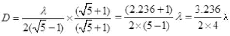
SHORT ANSWER TYPE QUESTIONS
Q.19. Figure shown a two slit arrangement with a source which emits unpolarised light. P is a polariser with axis whose direction is not given. If I0 is the intensity of the principal maxima when no polariser is present, calculate in the present case, the intensity of the principal maxima as well as of the first minima.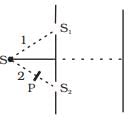 Ans. The resultant amplitude of wave reaching on screen will be the sum of amplitude of either wave in perpendicular and parallel polarisation.
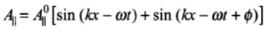
Amplitude of the wave in perpendicular polarisation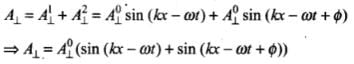
Amplitude of the wave in parallel polarisation
⇒ 
∴ Average Intensity on the screen
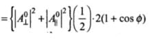
⇒ 
With polariser P.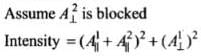
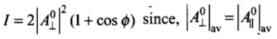
Given,  = Intensity without polariser at principal maxima.
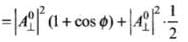
Intensity at first minima with polariser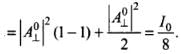
Q.20. A small transparent slab containing material of µ =1.5 is placed along AS2 (Fig.). What will be the distance from O of the principal maxima and of the first minima on either side of the principal maxima obtained in the absence of the glass slab.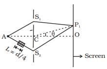 AC = CO = D, S1C = S2C = d << D
Ans. When ray AS2 passes through glass slab of thickness L and refractive index μ the path difference caused by slab is (μ - 1)L and path difference caused by Young’s double slit experiment is 2d sin θ. Total path difference at P2 is
∴ Δx = 2d sin θ + (μ - 1)L
For principal maxima, path difference Δx = 0
∴ 2d sinθ0+(μ - 1) L = 0 (For central maxima θ = θ0)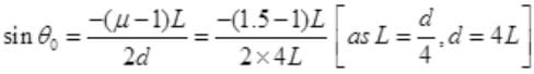
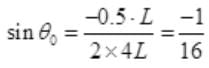
For central maxima, 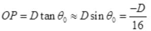
For small 
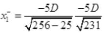
For the first minima the path difference = +λ/2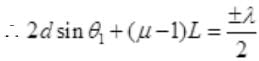 (For both upper and lower side from O]
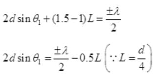
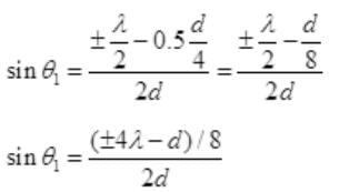
For diffraction, λ=d (half the slit dist.)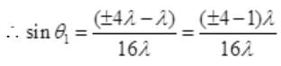
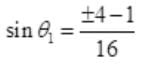
For positive direction side, sin 
For negative direction side, 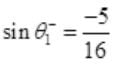
The distance of first minima from principal maxima on either side  are
are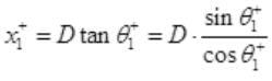
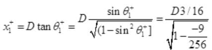
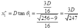 [above point O on screen]
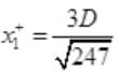
The first minima starts after the end of central maxima. So the Ist minima starts at distance of D tan 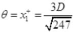 above O in positive direction.
The distance of first minima on the negative side is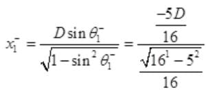
Q.21. Four identical monochromatic sources A,B,C,D as shown in the (Fig.) produce waves of the same wavelength λ and are coherent. Two receiver R1 and R2 are at great but equal distaces from B.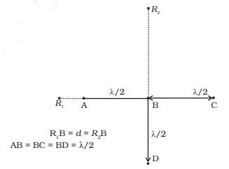 (i) Which of the two receivers picks up the larger signal?
(ii) Which of the two receivers picks up the larger signal when B is turned off?
(iii) Which of the two receivers picks up the larger signal when D is turned off?
(iv) Which of the two receivers can distinguish which of the sources B or D has been turned off?
Ans. (i) Let us consider the disturbances at the receiver R1, which is at a distance d from B.
Let the equation of wave at R1, because of A be
yA = a cos ωt ...(i)
The path difference of the signal from A with that from B is λ/2 and hence, the phase difference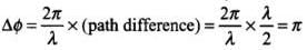
Thus, the wave equation at R1, because of B is
yB = a cos (ωt - π) = - a cos ωt ....(ii)
The path difference of the signal from C with that from A is A and hence the phase difference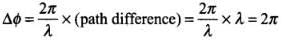
Thus, the wave equation a R1, because of C is
yC = a cos ωt = a cos (ωt - 2π) = a cos ωt ...(iii)
The path difference between the signal from D with that of A is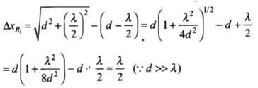
Therefore, phase difference is π.
∴ yD = a cos (ωt - π) = -a cos ωt ...(iii)
The resultant signal picked up at R1, from all the four sources is the summation of all four waves, 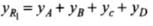

Thus, the signal picked up at R1 is zero.
Now let us consider the resultant signal received at R2. Let the equation of wave at R2. because of B be
yB = a1 cos ωt ....(i)
The path difference of the signal from D with that from B is λ/2 and hence, the phase difference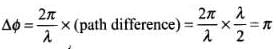
Thus, the wave equation at R2, because of D is
yB = a1 cos (ωt, - π) = -a1, cos ωt ...(ii)
The path difference between signal at A and that at B is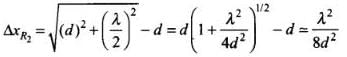
As d ≫ λ, therefore this path differences 
Hence, yB = a1 cos (ωt - ϕ)
Similarly, yB = a1 cos (ω1, - ϕ)
The resultant signal picked up at R2, from all the four sources is the summation of all four waves, 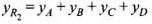
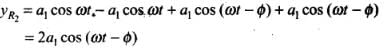
∴ Signal picked up by 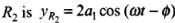
∴ 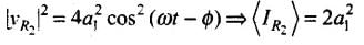
Thus. R2 picks up the larger signal.
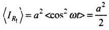
(ii) If B is switched off.
R1, picks upy = a cos ωt
∴ 
R2 picks up y = a cos ωt
∴ 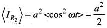
Thus, R1, and R2 pick up the same signal
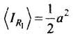
(iii) If D is switched off,
R1 picks up v = a cos ωt
∴ 
R2 picks up v = 3a cos ωt
∴ 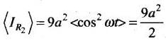
Thus. R2 picks up larger signal compared to R1.
(iv) Thus, a signal at R1, indicates B has been switched off and an enhanced signal at R2 indicates D has been switched off.
Q.22. The optical properties of a medium are governed by the relative permitivity (εr) and relative permeability (µr). The refractive index is defined as  For ordinary material εr > 0 and µr > 0 and the positive sign is taken for the square root. In 1964, a Russian scientist V. Veselago postulated the existence of material with εr < 0 and µr < 0. Since then such ‘metamaterials’ have been produced in the laboratories and their optical properties studied.
(i) According to the description above show that if rays of light enter such a medium from air (refractive index =1) at an angle θ in 2nd quadrant, them the refracted beam is in the 3rd quadrant.
(ii) Prove that Snell’s law holds for such a medium.
Ans. (i) If given postulate is true, then two parallel rays would proceed as shown in the figure (i).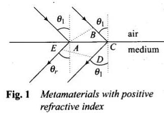
Again consider figure (i), let A B represent the incident wavefront and D E represent the refracted wavefront. All points on a wavefront must be in same phase and in turn, must have the same optical path length.
Thus 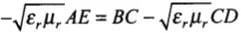
or 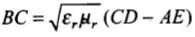
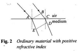
As showing that the postulate is reasonable. If however, the light proceeded in the sense it does for ordinary material (viz. in the fourth quadrant, Fig. 2)
Then 
or 
If BC > 0, then CD > AE
which is obvious from Fig. (i). Hence, the postulate is reasonable.
However, if the light proceed in the sense it does for ordinary material, (going from 2nd quadrant to 4th quadrant) as shown in Fig. (i). then proceeding as above,
or 
As AE > CD, therefore BC < 0 which is not possible. Hence, the given postulate is correct.
(ii) From Fig. (i),
and CD - AE = AC sin θr
As 
∴ 
or 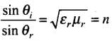
which proves Snell’s law.
Q.23. To ensure almost 100 per cent transmittivity, photographic lenses are often coated with a thin layer of dielectric material. The refractive index of this material is intermediated between that of air and glass (which makes the optical element of the lens).
A typically used dielectric film is MgF2 (n = 1.38). What should the thickness of the film be so that at the center of the visible spectrum (5500 Å) there is maximum transmission.
Ans. In the given figure incidence ray IA incident at point A from air to film surface with incident angle i. here at A, it gets partial reflection and refraction, passes through paths AR1 and AD respectively. AT D it again gets partial reflection (and refractions) from the glass and film interface surface. At C the interface surface of film and air and finally after refraction from C pass through path CR2 parallel to AR1.
The amplitude (intensity) of wave during refraction and reflection decreases.
If the interference due to two reflected rays AR1 and CR2 is destructive interference, then the reflected rays AR, and CR2 will not dominant.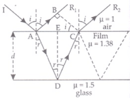 Both reflections are from lower to higher refractive index surfaces So, optical path difference between AR1 and CR2 will be
μ(AD + CD) - AB ...(I)
If d is the thickness of film then,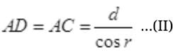
AB = AC sin i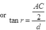
∴ d tan r = AC/2
AC = 2d tan r
Or
AB = 2d tan r sin i ...(III)
So the optical path difference from (I)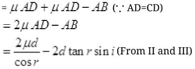
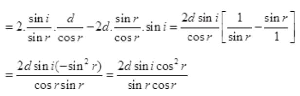
Optical path difference between AR1 and AR2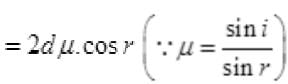
For two rays AR1 and CR2 to interfere destructively, path difference should be λ/2.
∴ 2d μ cos r = λ/2
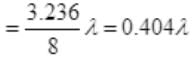
μd cos r = λ/4
For photographic lenses the sources are vertical planes i.e., rays incident at very small angle.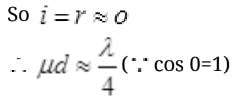
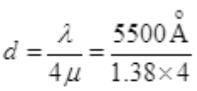
d = 1000Å
|
74 videos|314 docs|88 tests
|
FAQs on NCERT Exemplar: Wave Optics - Physics Class 12 - NEET
| 1. What is wave optics? |  |
| 2. How does wave optics differ from geometric optics? | |
| 3. What is interference in wave optics? | |
| 4. What is diffraction in wave optics? | |
| 5. How does polarization occur in wave optics? | |


Objective type Questions
,Important questions
,Semester Notes
,NCERT Exemplar: Wave Optics | Physics Class 12 - NEET
,Exam
,NCERT Exemplar: Wave Optics | Physics Class 12 - NEET
,ppt
,Extra Questions
,practice quizzes
,mock tests for examination
,Sample Paper
,study material
,past year papers
,shortcuts and tricks
,Previous Year Questions with Solutions
,video lectures
,Viva Questions
,Free
,MCQs
,Summary
,NCERT Exemplar: Wave Optics | Physics Class 12 - NEET
;


NCERT Exemplar: Wave Optics Free PDF Download
Importance of NCERT Exemplar: Wave Optics
NCERT Exemplar: Wave Optics Notes
NCERT Exemplar: Wave Optics NEET Questions
Study NCERT Exemplar: Wave Optics on the App
|
© EduRev
|
Education Revolution
|


|


within 7 days!