Chapter 7 - Measurements | Additional Study Material for Mechanical Engineering PDF Download
1. Basics of Measurements and Error Analysis (Static & Dynamic Characteristics of Measuring Instrument)
Fundamental Units
These include the following along with dimension and unit symbol.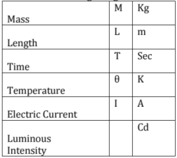
Performance Characteristics
- The performance characteristics of an instrument are mainly divided into two categories:
(i) Static characteristics
(ii) Dynamic characteristics - Set of criteria defined for the measurements, which are used to measure the quantities, which are slowly varying with time or almost constant, i,e do not vary with time, are called static characteristics
- When the quantity under measurement changes rapidly with time, the relation existing between input and output are generally expressed with the help of differential equations and are called dynamic characteristics
- The various performance characteristics are obtained in one form or another by a process called calibration
1. Accuracy
It is the degree of closeness with which the instrument reading approaches the true value of the quantity.
2. Static error
It is the difference between the measured value and true value of the quantity Mathematically δA = Am - At ........eq (1.1)
δA : absolute static error
Am: Measured value of the quantity.
At : True value of the quantity.
Relative error: (∈r) = δA/At
Percentage relative error:
From relative percentage error, accuracy is expressed as A = 1 - | ∈r|
Where A: relative accuracy and a = A x 100%
where a = percentage Accuracy.
- error can also be expressed as percentage of full scale reading (FSD) as,

3. Precision
It is the measure of degree of agreement within a group of measurements.
- High degree of precision does not guarantee accuracy.
Precision is composed of two characteristics
(i) Conformity.
(ii) Number of significant figures.
4. Significant Figures
- Precision of the measurement is obtained from the number of significant figures, in which the reading is expressed.
- Significant figures convey the actual information about the magnitude and measurement precision of the quantity.
5. Sensitivity
The sensitivity denotes the smallest change in the measured variable to which the instrument responds.
It is defined as the ratio of the changes in the output of an instrument to a change in the value of the quantity to be measured.
Mathematically it is expressed as,
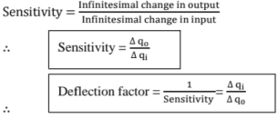
6. Resolution
Resolution is the smallest measurable input change.
7. Threshold
If the input quantity is slowly varied from zero onwards, the output does not change until some minimum value of the input is exceeded. This minimum value of the input is called threshold.
Resolution is the smallest measurable input change while the threshold is the smallest measurable input.
8. Linearity
Linearity is the ability to reproduce the input characteristics symmetrically and linearly. Graphically such relationship between input and output is represented by a straight line.
The graph of output against the input is called the calibration curve, The linearity property indicates the straight line nature of the calibration curve.
Thus, the linearity is defined as,
9. Zero Drift
The drift is the gradual shift of the instrument indication, over an extended period during which the value of the input variable does not change.
10. Reproducibility
It is the degree of closeness with which a given value may be repeatedly measured. It may be specified interms of units for a given period of time.
11. Repeatability
Repeatability is defined as variation of scale reading and is random in nature. Both reproducibility and the repeatability are a measure of the closeness with which a given input may be measured again and again. The Fig shows the input and output relationship with positive and negative repeatability.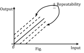
12. Stability
The ability of an instrument to retain its performance throughout its specified operating life and the storage life is defined as its stability.
13. Tolerance
The maximum allowable error in the measurement is specified interms of some value which is called tolerance. This is closely related to the accuracy.
14. Range or Span
The minimum and maximum values of a quantity for which an instrument is designed to measure is called its range or span. Sometimes the accuracy is specified interms of range or span of an instrument.
Limiting Errors/ Relative Limiting Error
Guarantee Errors: The limits of deviations from the specified value are defined as limiting errors or guarantee errors.
Actual value of quantity = A= An ± δa; δa: limiting error or tolerance
An: specified or rated value
- It is also called as fractional error. It is the ratio of the error to the specified magnitude of a quantity.

Combination of Quantities with Limiting Errors
1. Sum of the Two Quantities: Let a1 and a2 be the two quantities which are to be added to obtain the result as AT.

2. Difference of the Two Quantities
3. Product of the Two Quantities
4. Division of the Two Quantities
5. Power of a factor
Types of Errors
The static error may arise due to number of reasons. The static errors are classified as
- Gross errors
- Systematic errors
- Random errors
1. Step input
= A/S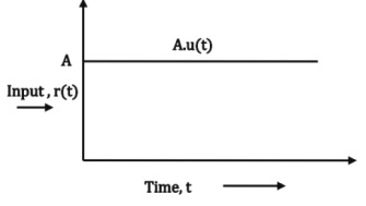
2. Ramp input
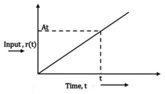
3. Parabolic input
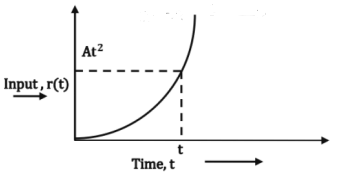
4. Impulse input

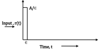
Response of First Order System to a Unit Step Input
C(t) = 1 - e-t/τ
em(t) = e-t/τ
ess = limt →∞ em (t) = 0
Ramp Response of a First Order System
C(t) = 1 - τ[1 - e-t/τ]
em = τ[1 - e-t/τ]
ess = τ
Impulse Response of a First Order System
2. Measurements of Basic Electrical Quantities 1 (Current Voltage, Resistance)
Indicating Instruments
Analog Instruments
Analog instruments are classified in one way as
(a) Indicating
(b) Recording
(c) Integrating Instruments.
Essential Requirements of an Instrument
For satisfactory operation of any indicating instrument, following systems must be present in an instrument.
1. Deflecting system producing deflecting toque Td
2. Controlling system producing controlling torque Tc
3. Damping system producing damping torque.
The deflecting system uses one of the following effects produced by current or voltage, to produce deflecting torque.
1. Magnetic Effect: When a current carrying conductor is placed in uniform magnetic field, it experiences a force which causes it to move. This effect is mostly used in many instruments like moving iron attraction and repulsion type, permanent magnet moving coil instruments etc.
2. Thermal Effect: The current to be measured is passed through a small element which heats it to cause rise in temperature which is converted to an e.m.f. by a thermocouple attached to it.
When two dissimilar metals are connected end to end, to form a closed loop and the two junctions formed are maintained at different temperatures, then e.m.f. is induced which causes the flow of current through the closed circuit which is called a thermocouple.
3. Electrostatic Effect: When two plates are charged, there is a force exerted between them, which moves one of the plates. This effect is used in electrostatic instruments which are normally voltmeters.
4. Induction Effect: When a non-magnetic conducting disc is placed in a magnetic field produced by electromagnets which are excited by alternating currents, an e.m.f. is induced in it.
If a closed path is provided, there is a flow of current in the disc. The interaction between induced currents and the alternating magnetic fields exerts a force on the disc which causes to move it. This interaction is called an induction effect. This principle is mainly used in energymeters.
5. Hall Effect: If a semiconductor material is placed in uniform magnetic field and if it carries current, then an e.m.f. is produced between two edges of conductor. The magnitude of this e.m.f. depends on flux density of magnetic field, current passing through the conducing bar and hall effect co-efficient which is constant for a given semiconductor. This effect is mainly used in flux-meters.
Controlling System
It produces a force equal and opposite to the deflecting force in order to make the deflection of pointer at a definite magnitude.
Damping System
The quickness with which the moving system settles to the final steady position depends on relative damping.
Three types of damping exists
1. Critically damped
2. Under damped
3. Over damped Effect of damping on deflection
The following methods are used to produce damping torque.
1. Air friction damping
2. Fluid friction damping
3. Eddy current damping.
Measurement of Voltage and Current
Analog Ammeter and Voltmeters
The Instruments used for measurement of voltage and current can be classified as:
(a) Moving coil instruments
- Permanent magnet type
- Dynamometer type
(b) Moving iron instruments
(c) Electrostatic Instruments
(d) Rectifier instruments
(e) Induction instruments
(f) Thermal instruments
- Hot - wire type
- Thermocouple type
(a) Moving Coil Instruments
(i) Permanent Magnet Type: It works on the principle of magnetic effect
Torque equation:
The deflecting torque Td is given by
Td - NBAI
Where Td - deflecting torque in N - m
B - Flux density in air gap Wb/m2.
N - Numbers of turns of the coil
A - effective coil area m2 (l x b)
l - length; b - breadth of the coil
I - current in the moving coil, amperes
The controlling torque is provided by springs and is proportional to angular deflection of the pointer
Tc = Kθ
Where Tc = controlling torque
K = spring constant, Nm/rad or Nm/deg
θ = Angular deflection.
For the final steady state position,
G = NBA
* Thus we get a linear relation between current and deflection angle.
• Damping used in this type of instrument is eddy current damping.
(ii) Dynamometer Type
- Dynamometer instrument uses the current under measurement to produce the magnetic field.
- Deflecting Torque
 Where i1 = instantaneous value of current in fixed coils; A
i2 = Instantaneous value of current in moving coil; A
M = Mutual inductance between fixed and moving coil; H
Operation with D,C

Operation with AC
T = time period for one complete cycle.
Electrodynamometer Ammeters
Range: upto 100 mA.
Electrodynamometer Voltmeter
(b) Moving Iron Instruments
Moving iron instruments depend for their indication upon the movement of a piece of soft iron in the field of a coil produced by the current to be measured.
Where I is the current through the coil and L is the inductance.
Linearization of Scale: Compensation towards frequency errors can be done by connecting a capacitor across a part of series resistance in Mi voltmeter, C = 0.41 x (L/R2)
(c) Electrostatic Instruments
For linear motion:
For angular motion:
(d) Rectifier Instruments
Half wave Rectifier type Instruments
Full wave rectifier type instruments:
Shunts and Multipliers
Shunts and multipliers are the resistance connected in shunt or series with ammeter and voltmeters to enhance their measuring capacity.
➤ Shunt with ammeter
Instrument constant,
➤ Multiplier with Voltmeter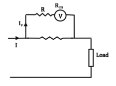

➤ Shunt for a.c. instruments Multiplication factor
➤ Multipliers for Moving - Iron Instruments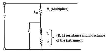
voltage multiplying factor (m)
Measurement of Resistance
➤ Measurement of Low Resistance
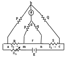
Kelvin's Double Bridge is used for the measurement of low resistance as shown in fig
➤ Measurement of Medium Resistance
Two wires are required to represent a medium resistance:
This can be measured by:
(a) Ammeter voltmeter method
(b) Wheatstone bridge method
(c) Ohm meter
(a) Voltmeter - Ammeter Method
From fig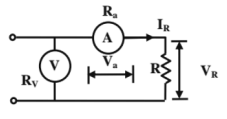
Measured value of resistance,
Where R is the true value of the resistance.
Error = Ra % Error = (Ra/R)
This method is suitable for measurement of high resistance, among the range.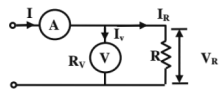
Ammeter - Voltmeter Method

This method is suitable for measurement of low resistance among the range.
The resistance where both the methods give same error is obtained by equating the two errors.
(b) Wheat stone Bridge
Sensitivity of the galvanometer, Sv = θ/e
Where θ = deflection of the galvanometer
e = emf across galvanometer
Sensitivity of galvanometer,

Sensitivity of the Bridge
➤ Measurement of High Resistance
Loss of charge method

3. Measurements of Basic Electrical Quantities 2 (Power and Energy, Instrument Transformers)
1. Power In D.C. Circuits
In case of fig (a)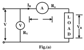
Power measured
True value = Measured power - power loss in ammeter
In case of fig (b)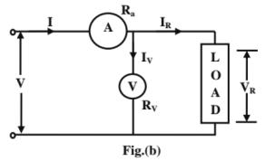
Power measured (Pm2) = VRIR + (V2R / Rv)
True power = Measured power - power loss in voltmeter
2. Power In A.C. Circuits
Instantaneous power = VI
Average power = VI cos (Ф)
Where V and I are r.m.s values of voltage and current and cos Ф is the power factor of the load.
3. Electro Dynamometer Wattmeter: This type of wattmeter is mostly used to measure power. The deflecting torque in electrodynamometer instruments is given by,
Many watt meters are compensated for errors caused by inductance of pressure coil by means of a capacitor connected in parallel with a portion of multiplier.
Capacitance C = (L/r2)
4. Low Power Factor Wattmeter
Td = ipic (dM /dθ)
Average deflection torque = IPI cos (Ф) (dM / dθ)
= (V / Rp). I cos (Ф) (dM / dθ)
Td ∝ VI cos Ф (dM/ dθ)
∝ power, if (dM / dθ) is constant.
5. Errors in Electro Dynamometer Wattmeter
True Power for lagging pf loads

True Power for leading pf loads
ERROR = tan Ф tan β x true power, Ф = pf angle, β = tan-1 (Xp / RP) = VI sin Ф tan β
% ERROR = tan Ф tan β x 100
β → is the angle between PC current and voltage.
6. Measurement of Power in Three Phase Circuits
(a) Three watt meter Method: The figure depicts three wattmeter method to determine the power in 3 - Ф, 4 wire system.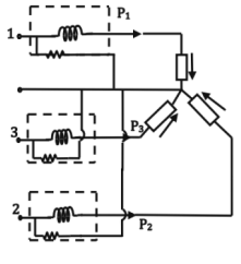
Sum of the instantaneous readings of watt meters
= P = P1 + P2 + P3
= V1i1 + V2 i2 + V3 i3
i3 Instantaneous power of load = V1 i1 + V2 i2 + V3i3
Hence the summation of readings of three watt meters gives the total power of load.
(a) Two Wattmeter Method
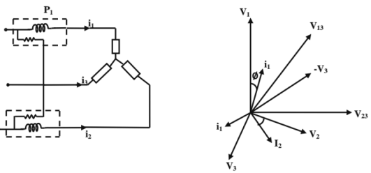
Sum of reading of two wattmeters = 3 VI cos Φ
Difference of readings of two watt meters = √3 VI sin Φ
∴ Reactive power consumed by load = √3 (Difference of two wattmeter readings) = √3 (P1 - P2)
Power factor cos Φ
7. Measurement of Reactive Power in Three Phase Circuits
Reading of wattmeter = V23 i1 cos (angle between i1 and V23)
= V23 i1 cos (90 - Φ)
= √3 V I sin Φ
Total reactive power of the circuit
= √3 (watt meter reading).
4. Electronic Measuring Instruments 1 (Analog, Digital Meters & Bridges, ADC type DVM)
The general ac bridge circuit is as follows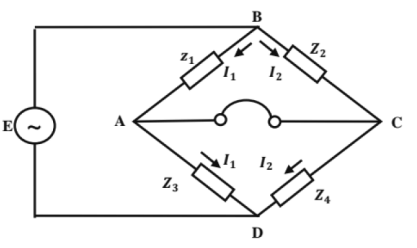
Under balanced condition
Z1Z4∠(θ1 + θ4) = Z2Z3∠(θ2 + θ3)
Equating the magnitudes and angles,
Z1 Z4 = Z2 Z3
θ1 + θ4 = θ2 + θ3
Measurement of Self Inductance
1. Hay's Bridge
- Used for measurement of high Q coils, shown in figure.

At balance
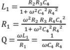
2. Owners Bridge
- Used for measurement of inductance in terms of capacitance, shown in figure.
 Under balance condition:
L4 = R2 R3 R4
3. Maxwell Inductance Bridge
- This bridge measures inductance by comparison with a variable standard self - inductance, shown in figure
 At balance
4. Maxwell's Inductance - Capacitance Bridge
- Here inductance is measured by comparison with standard variable capacitance, shown in figure.
 At balance
- Useful for measurement of low Q coils (1 < Q < 10)
5. Anderson's Bridge:
- In this method, self - Inductance is measured in terms of a standard capacitor, shown in fig below
- Applicable for precise measurement of self - inductance over a very wide range of values
 At balance
L1 = C R3 [r (R4 + R2) + R2 R4]R4.
Measurement of Capacitance
1. De Sauty's Bridge
- It measures the unknown capacitance by comparing with a standard capacitor, shown in figure
 At balance:
2. Modifed De Sauty's Bride
 At balance
Dissipation factor, D = tan δ1 = ωC1r1
D2 = tan δ2 = (ω) C2r2
3. Schering Bridge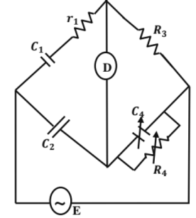
At balance condition

C1 = C2 (R2 / R3)
Dissipation factors D1 = tan δ1 = ωC1r1 = C4r3.
Digital Voltmeters
Type of DVM's
1. Ramp Type DVM: The operating principle is to measure the time that a linear ramp voltage takes to change from level of input voltage to zero voltage or vice - versa.
2. Integrating Type Digital Voltmeter: The frequency of the saw tooth wave (E0) is a function of the value of Es, the voltage being measured. The number of pulses produced in a given time interval and hence the frequency of saw tooth wave is an indication of the value of voltage being measured.
3. Potentiometric Type DVM: A potentiometric type of DVM, employs voltage comparison technique. In this DVM the unknown voltage is compared with a reference voltage whose value is fixed by the setting of the calibrated potentiometer.
5. Electronic Measuring Instruments 2 (C.R.O., RF Meters, Special Meters, Q meter)
Cathode Ray Tube(CRO)
For electrostatic deflection
Deflection
D - Deflection, m
L - distance from centre of deflection plates to screen, m
Ld - effective length of deflection plates, m
Ed - deflection voltage, volts d - separation between the plates, m
Ea- accelerating voltage, volts
Deflection sensitivity is
Deflection factor G is
Oscilloscope Specifications
1. Sensitivity: It means the vertical sensitivity. It refers to smallest deflection factor G = (1 / s) and expressed, as mv / div. The alternator of the vertical amplifier is calibrated in mv / div.
2. Bandwidth: It is the range of frequencies between ± 3 dB of centre frequency.
3. Rise Time: Rise time is the time taken by the pulse to rise from 10% to 90% of its amplitude.
BW = 1/2πRC = band width in MHz
90% of amplitude is normally reached in 2.2 RG or 2.2 time constants.
Tr = rise time in μ second
Synchronization means the frequency of vertical signal input as an integral multiple of the sweep frequency.
Fin = nFs
Measurement Of Phase Difference And Frequency
If Vx and Vy be the instantaneous values and of voltages applied to the deflection plates x and y and let them be expressed as
Vx = Vx sin ωxt Vy = Vy sin (ωy t - Ф)
By adjusting the values of toy, ωx, ωy, Vx, Vy and Ф suitably, various patterns may De obtained on the screen.
1. When ωx = ωy = ω, Ф = 0, then (Vx / Vy) = (Vx / Vy) = K is an equation of straight line passing through origin and making an angle of tan θ = (Vy / Vx) with horizontal.
2. ωx = ωy = ωy, Ф = (π/4) ⇒ an ellipse whose major axis has a slope of (Vx / Vy)
3. ωx = ωy = ωy, Ф = (π/2) radians ⇒ a circle.
4. When ωx = 2ωy, we get Fig (i). When ωy = 2ωx we get Fig (ii).
Q - Meter
The Q meter is an instrument which is designed to measure the value of the circuit Q directly and as such is very useful in measuring the characteristics of coil and capacitors.
The storage factor Q of a Q network is equal to
Q = ω0L/R where,
ω0 = resonant angular freq
L = inductance of coil
R = effective resistance of coil
Shielding
Electromagnetic shielding is the process of limiting the penetration of electromagneticflelds into a space, by blocking them with a barrier made of conductive material.
Grounding
Grounding electrically interconnects conductive objects to keep voltages between them safe, even if equipment fails.
|
1 videos|30 docs|57 tests
|
|
1 videos|30 docs|57 tests
|

|
Explore Courses for Mechanical Engineering exam
|

|


 Where i1 = instantaneous value of current in fixed coils; A
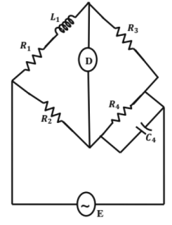
 Under balance condition:
 At balance
 At balance:


