Mechanical Engineering Exam  >  Mechanical Engineering Notes  >  Strength of Materials (SOM)  >  GATE Past Year Questions: Shear Force & Bending Moment Diagrams

GATE Past Year Questions: Shear Force & Bending Moment Diagrams | Strength of Materials (SOM) - Mechanical Engineering PDF Download

 Q1: A horizontal beam of length 1200 mm is pinned at the left end and is resting on a roller at the other end as shown in the figure. A linearly varying distributed load is applied on the beam. The magnitude of maximum bending moment acting on the beam is _____ N.m. (round off to 1 decimal place).      (2024)
GATE Past Year Questions: Shear Force & Bending Moment Diagrams | Strength of Materials (SOM) - Mechanical Engineering
(a) 9.2

(b) 6.2

(c) 12.5
(d) 16.5

Ans:(a) 

Sol:
GATE Past Year Questions: Shear Force & Bending Moment Diagrams | Strength of Materials (SOM) - Mechanical Engineering

BM at a distance ' x ' from end (A)=Mx
GATE Past Year Questions: Shear Force & Bending Moment Diagrams | Strength of Materials (SOM) - Mechanical Engineering

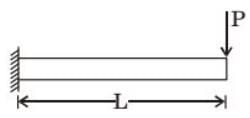
 Q2: A beam of length  L is loaded in the xy−plane by a uniformly distributed load, and by a concentrated tip load parallel to the z−axis, as shown in the figure. The resulting bending moment distributions about the  z−axis, as shown in the figure. The resulting bending moment distributions about the 𝑦- z axes are denoted by My and  M z , respectively.      (2023)
Which one of the options given depicts qualitatively CORRECT variations of My and  M z along the length of the beam?
GATE Past Year Questions: Shear Force & Bending Moment Diagrams | Strength of Materials (SOM) - Mechanical Engineering
(a) A

(b) B 

(c) C
(d) D 

Ans:(b)

Sol:

GATE Past Year Questions: Shear Force & Bending Moment Diagrams | Strength of Materials (SOM) - Mechanical Engineering

Udl will produced bending moment diagram about  𝑧  axis (M2)
GATE Past Year Questions: Shear Force & Bending Moment Diagrams | Strength of Materials (SOM) - Mechanical Engineering

Point load will produce bending moment diagram about -𝑦axis (M𝑦).
GATE Past Year Questions: Shear Force & Bending Moment Diagrams | Strength of Materials (SOM) - Mechanical Engineering

Q3: A beam of negligible mass is hinged at support P and has a roller support Q as shown in the figure.      (2020 SET2)
GATE Past Year Questions: Shear Force & Bending Moment Diagrams | Strength of Materials (SOM) - Mechanical Engineering

A point load of 1200 N is applied at point R. The magnitude of the reaction force at support Q is __________ N.
(a) 3000
(b) 1500
(c) 300
(d) 750

Ans: (b)
Sol:


GATE Past Year Questions: Shear Force & Bending Moment Diagrams | Strength of Materials (SOM) - Mechanical Engineering 

GATE Past Year Questions: Shear Force & Bending Moment Diagrams | Strength of Materials (SOM) - Mechanical Engineering

Q4: The magnitude of reaction force at joint C of the hinge-beam shown in the figure is _______ kN (round off to 2 decimal places).(2020Set1) 

GATE Past Year Questions: Shear Force & Bending Moment Diagrams | Strength of Materials (SOM) - Mechanical Engineering
(a) 40
(b) 10
(c) 50

(d) 20

Ans:(d)
Sol:

GATE Past Year Questions: Shear Force & Bending Moment Diagrams | Strength of Materials (SOM) - Mechanical Engineering
4Rc= 10x4x2
Rc = 20kN 

     Q5: The barrier shown between two water tanks of unit width (1 m) into the plane of the screen is modeled as a cantilever.
GATE Past Year Questions: Shear Force & Bending Moment Diagrams | Strength of Materials (SOM) - Mechanical Engineering

aking the density of water as 1000 kg/m3  and the acceleration due to gravity as  10/ms2,  the maximum absolute bending moment developed in the cantilever is ______ kNm (round off to the nearest integer).       (2020 Set1)
(a) 85
(b) 105
(c) 128
(d) 146
Ans: (b)

Sol:
GATE Past Year Questions: Shear Force & Bending Moment Diagrams | Strength of Materials (SOM) - Mechanical Engineering

Q6: A simply supported beam of width 100 mm, height 200 mm and length 4 m is carrying a uniformly distributed load of intensity 10 kN/m. The maximum bending stress (in MPa) in the beam is __________ (correct to one decimal place).      (2018 Set1)
GATE Past Year Questions: Shear Force & Bending Moment Diagrams | Strength of Materials (SOM) - Mechanical Engineering
(a) 25

(b) 30
(c) 35

(d) 50
Ans: (b)
Sol:
  Maximum B.M.. M GATE Past Year Questions: Shear Force & Bending Moment Diagrams | Strength of Materials (SOM) - Mechanical Engineering (L=4)
Maximum Bending Stress
GATE Past Year Questions: Shear Force & Bending Moment Diagrams | Strength of Materials (SOM) - Mechanical Engineering

Q7:   For a loaded cantilever beam of uniform cross-section, the bending moment (in N.mm) along the length is  𝑀 ( 𝑥) =  52 𝑥5+10x, where x is the distance  (in mm) measured from the free end of the beam. The magnitude of shear force (in N) in the cross-section at x=10 mm is      (2017Set2)
(a) 100
(b) 105
(c) 110
(d) 115
Ans:(c) 

Sol: 
GATE Past Year Questions: Shear Force & Bending Moment Diagrams | Strength of Materials (SOM) - Mechanical Engineering

We know that at section X-X
GATE Past Year Questions: Shear Force & Bending Moment Diagrams | Strength of Materials (SOM) - Mechanical Engineering

Q8: For the overhanging beam shown in figure, the magnitude of maximum bending moment (in kN-m) is ________      (2015 Set3)
GATE Past Year Questions: Shear Force & Bending Moment Diagrams | Strength of Materials (SOM) - Mechanical Engineering
(a) 54

(b) 36
(c) 40
(d) 14

Ans: (c)
Sol:

GATE Past Year Questions: Shear Force & Bending Moment Diagrams | Strength of Materials (SOM) - Mechanical Engineering
                         GATE Past Year Questions: Shear Force & Bending Moment Diagrams | Strength of Materials (SOM) - Mechanical Engineering
Taking x from A

GATE Past Year Questions: Shear Force & Bending Moment Diagrams | Strength of Materials (SOM) - Mechanical Engineering

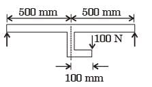
Q9: The value of moment of inertia of the section shown in the figure about the axis-XX is     (2015 Set3)
GATE Past Year Questions: Shear Force & Bending Moment Diagrams | Strength of Materials (SOM) - Mechanical Engineering
(a) 8.5050 x106mm4
(b) 6.8850x106mm4
(c) 7.7625x106mm4
(d) 8.5725x 106mm4

Ans:(b) 

Sol: 
GATE Past Year Questions: Shear Force & Bending Moment Diagrams | Strength of Materials (SOM) - Mechanical Engineering

Q10:  A cantilever beam OP is connected to another beam PQ with a pin joint as shown in the figure. A load of 10 kN is applied at the mid-point of PQ. The magnitude of bending moment (in kN-m) at fixed end O is       (2015Set2)
GATE Past Year Questions: Shear Force & Bending Moment Diagrams | Strength of Materials (SOM) - Mechanical Engineering

(a) 2.5

(b) 5
(d) 10

(c)25

Ans: (c) 
Sol:
GATE Past Year Questions: Shear Force & Bending Moment Diagrams | Strength of Materials (SOM) - Mechanical Engineering

At hinge moment releases

Taking summation of all forces

GATE Past Year Questions: Shear Force & Bending Moment Diagrams | Strength of Materials (SOM) - Mechanical Engineering

Taking moment of all forces about Q

GATE Past Year Questions: Shear Force & Bending Moment Diagrams | Strength of Materials (SOM) - Mechanical Engineering

Summation of all vertical forces is zero.
GATE Past Year Questions: Shear Force & Bending Moment Diagrams | Strength of Materials (SOM) - Mechanical Engineering
Summation of Moments of all forces at equilibrium is zero.
GATE Past Year Questions: Shear Force & Bending Moment Diagrams | Strength of Materials (SOM) - Mechanical Engineering


Question for GATE Past Year Questions: Shear Force & Bending Moment Diagrams
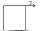
Try yourself:A block of steel is loaded by a tangential force on its top surface while the bottom surface is held rigidly. The deformation of the block is due to 
GATE Past Year Questions: Shear Force & Bending Moment Diagrams | Strength of Materials (SOM) - Mechanical Engineering
View Solution

Question for GATE Past Year Questions: Shear Force & Bending Moment Diagrams
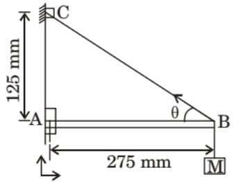
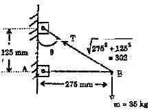
Try yourself:A mass of 35 kg is suspended from a weightless bar AB which is supported by a cable CB and a pin at A as shown in figure. The pin reactions at A on the bar AB are​
GATE Past Year Questions: Shear Force & Bending Moment Diagrams | Strength of Materials (SOM) - Mechanical Engineering

[1997]

View Solution

Question for GATE Past Year Questions: Shear Force & Bending Moment Diagrams
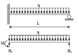
Try yourself:A uniformly loaded propped cantilever beam and its free body diagram are shown below. The reactions are
GATE Past Year Questions: Shear Force & Bending Moment Diagrams | Strength of Materials (SOM) - Mechanical Engineering

[2007]

View Solution

Question for GATE Past Year Questions: Shear Force & Bending Moment Diagrams
Try yourself:A simply supported beam PQ is loaded by a moment of 1 kNm at the mid-span of the beam as shown in the figure. The reaction forces Rp and RQ at supports P and Q respectively are
GATE Past Year Questions: Shear Force & Bending Moment Diagrams | Strength of Materials (SOM) - Mechanical Engineering

[2011]

View Solution

Question for GATE Past Year Questions: Shear Force & Bending Moment Diagrams
Try yourself:A simply supported beam of length L is subjected to a varying distributed load sin (3px/L) Nm-1, where the distance x is measured from the left support. The magnitude of the vertical reaction force in N at the left support is

[2013]

View Solution

Question for GATE Past Year Questions: Shear Force & Bending Moment Diagrams
Try yourself:For a simply supported beam on two end supports, the bending moment is maximum

[1989]

View Solution

Question for GATE Past Year Questions: Shear Force & Bending Moment Diagrams
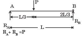
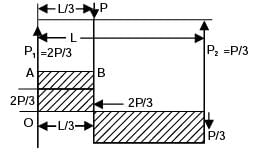
Try yourself:A concentrated load P acts on a simply supported beam of span L at a distance L/3 from the left support. The bending moment at the point of application of the load is given by

[1993]

View Solution

Question for GATE Past Year Questions: Shear Force & Bending Moment Diagrams
Try yourself:A concentrated load Pacts on a simply supported beam of span L at a distance L/3 from the left support. The bending moment at the point of application of the load is given by

[2003]

View Solution

Question for GATE Past Year Questions: Shear Force & Bending Moment Diagrams
Try yourself:A steel beam of breadth 120 mm and height 750 mm is loaded as shown in the figure.Assume Esteel = 200 GPa.The beam is subjected to a maximum bending moment of
GATE Past Year Questions: Shear Force & Bending Moment Diagrams | Strength of Materials (SOM) - Mechanical Engineering

[2004]

View Solution

Question for GATE Past Year Questions: Shear Force & Bending Moment Diagrams
Try yourself:A steel beam of breadth 120 mm and height 750 mm is loaded as shown in the figure. Assume Esteel = 200 GPa. The value of maximum deflection of the beam is
GATE Past Year Questions: Shear Force & Bending Moment Diagrams | Strength of Materials (SOM) - Mechanical Engineering

[2004]

View Solution

Question for GATE Past Year Questions: Shear Force & Bending Moment Diagrams
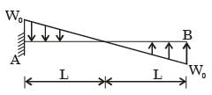
Try yourself:A cantilever beam carries the antisymmetric load shown, where W0 is the peak intensity of the distributed load. Qualitatively, the correct bending moment diagram for this beam is
GATE Past Year Questions: Shear Force & Bending Moment Diagrams | Strength of Materials (SOM) - Mechanical Engineering

[2005]

View Solution

Question for GATE Past Year Questions: Shear Force & Bending Moment Diagrams
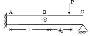
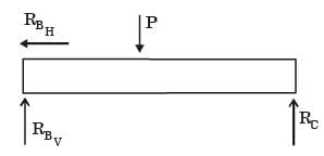
Try yourself:A beam is made up of two identical bars AB and BC, by hinging them together at B. The end A is built-in (cantilevered) and the end C is simplysupported. With the load P acting as shown, the bending moment at A is
GATE Past Year Questions: Shear Force & Bending Moment Diagrams | Strength of Materials (SOM) - Mechanical Engineering

[2005]

View Solution

Question for GATE Past Year Questions: Shear Force & Bending Moment Diagrams
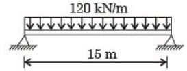
Try yourself:A simply supported beam of span length 6 m and 75 mm diameter carries a uniformly distributed load of 1.5 kN/m. 14. What is  he maximum value of bending moment?

[2006 : 2 Marks]

View Solution

Question for GATE Past Year Questions: Shear Force & Bending Moment Diagrams
Try yourself:A simply supported beam of span length 6 m and 75 mm diameter carries a uniformly distributed load of 1.5 kN/m. What is the maximum value of bending stress?

[2006 : 2 Marks]

View Solution

Question for GATE Past Year Questions: Shear Force & Bending Moment Diagrams
Try yourself: In a simply-supported beam loaded as shown below, the maximum bending moment in Nm is​
GATE Past Year Questions: Shear Force & Bending Moment Diagrams | Strength of Materials (SOM) - Mechanical Engineering

[2007]

View Solution

Question for GATE Past Year Questions: Shear Force & Bending Moment Diagrams
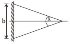
Try yourself:A tapered cantilever beam of constant thickness is loaded as shown in the sketch below. The bending stress will be
GATE Past Year Questions: Shear Force & Bending Moment Diagrams | Strength of Materials (SOM) - Mechanical Engineering

[1988]

View Solution

Question for GATE Past Year Questions: Shear Force & Bending Moment Diagrams
Try yourself:Which one of the following diagrams shows correctly the distribution of transverse shear stress across the depth h of a rectangular beam subjected to varying bending moment along its length?
View Solution

The document GATE Past Year Questions: Shear Force & Bending Moment Diagrams | Strength of Materials (SOM) - Mechanical Engineering is a part of the Mechanical Engineering Course Strength of Materials (SOM).
All you need of Mechanical Engineering at this link: Mechanical Engineering
37 videos|39 docs|45 tests

Top Courses for Mechanical Engineering

FAQs on GATE Past Year Questions: Shear Force & Bending Moment Diagrams - Strength of Materials (SOM) - Mechanical Engineering

1. What are Shear Force and Bending Moment Diagrams in Mechanical Engineering?
Ans. Shear Force and Bending Moment Diagrams are graphical representations of the internal forces acting on a beam or a structural element. Shear Force is the force that causes a portion of the beam to slide in one direction relative to an adjacent part, while Bending Moment is the internal moment that causes a beam to bend.
2. How are Shear Force and Bending Moment Diagrams useful in Mechanical Engineering?
Ans. Shear Force and Bending Moment Diagrams help engineers analyze and design structures by providing a visual representation of the internal forces and moments acting on the beam. They are crucial for determining where the beam is likely to fail or deform under different loading conditions.
3. What do the shapes of Shear Force and Bending Moment Diagrams indicate?
Ans. The shape of the Shear Force Diagram indicates the change in shear force along the length of the beam, while the shape of the Bending Moment Diagram shows the variation in bending moment. Peaks and valleys in the diagrams indicate points of maximum shear force or bending moment.
4. How can one determine the maximum shear force and bending moment from the diagrams?
Ans. The maximum shear force occurs at the point where the Shear Force Diagram changes sign, while the maximum bending moment occurs at the point where the Bending Moment Diagram crosses the zero axis. Engineers can use these diagrams to precisely determine these critical values.
5. What are some common applications of Shear Force and Bending Moment Diagrams in Mechanical Engineering?
Ans. Shear Force and Bending Moment Diagrams are widely used in the design of bridges, buildings, and other structures to ensure their stability and safety under different loading conditions. They are also essential in the analysis of mechanical components like beams and shafts to prevent failure.
37 videos|39 docs|45 tests
Download as PDF
Explore Courses for Mechanical Engineering exam

Top Courses for Mechanical Engineering

Signup for Free!
Signup to see your scores go up within 7 days! Learn & Practice with 1000+ FREE Notes, Videos & Tests.
10M+ students study on EduRev
Related Searches

Exam

,

Free

,

pdf

,

ppt

,

Important questions

,

mock tests for examination

,

Extra Questions

,

Objective type Questions

,

GATE Past Year Questions: Shear Force & Bending Moment Diagrams | Strength of Materials (SOM) - Mechanical Engineering

,

GATE Past Year Questions: Shear Force & Bending Moment Diagrams | Strength of Materials (SOM) - Mechanical Engineering

,

practice quizzes

,

Semester Notes

,

Viva Questions

,

Summary

,

Previous Year Questions with Solutions

,

past year papers

,

shortcuts and tricks

,

MCQs

,

Sample Paper

,

GATE Past Year Questions: Shear Force & Bending Moment Diagrams | Strength of Materials (SOM) - Mechanical Engineering

,

video lectures

,

study material

;