GATE Past Year Questions: Torsion of Shafts

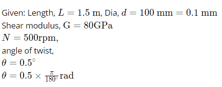
Q1: A cylindrical transmission shaft of length 1.5 m and diameter 100 mm is made of a linear elastic material with a shear modulus of 80 GPa. While operating at 500 rpm, the angle of twist across its length is found to be 0.5 degrees. The power transmitted by the shaft at this speed is _______kW. (Rounded off to two decimal places) Take π=3.14. (2023)
A. 238.64
B. 254.35
C. 632.25
D. 456.35
Ans: (a)
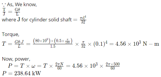
Sol: 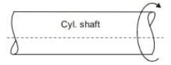
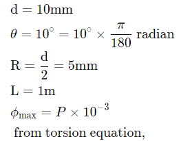
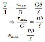
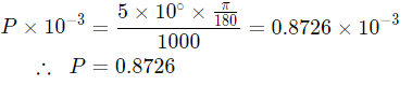
Q2: A cylindrical rod of diameter 10 mm and length 1.0 m is fixed at one end. The other end is twisted by an angle of 10º by applying a torque. If the maximum shear strain in the rod is p x 10-3, then p is equal to ______ (round off to two decimal places). (2019 Set - 1)
A. 0.25
B. 0.5
C. 0.8
D. 0.6
Ans: (c)
Sol: 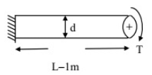
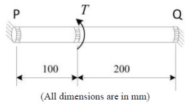
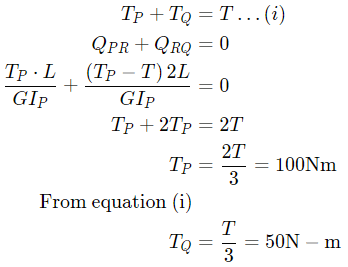
Q3: A bar of circular cross section is clamped at ends P and Q as shown in the figure. A torsional moment T=150 Nm is applied at a distance of 100 mm from end P. The torsional reactions (TP, TQ) in Nm at the ends P and Q respectively are (2018 Set -2)
(a) (50,100)
(b) (75,75)
(c) (100,50)
(d) 120,30)
Ans: (c)
Sol: 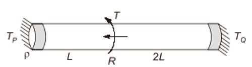
Q4: A hollow circular shaft of inner radius 10 mm, outer radius 20 mm, and length 1 m is to be used as a torsional spring. If the shear modulus of the material of the shaft is 150 GPa, the torsional stiffness of the shaft (in kN-m/rad) is ________ (correct to two decimal places). (2018 Set -2)
A. 12.36
B. 18.26
C. 35.34
D. 48.22
Ans: (c)
Sol: 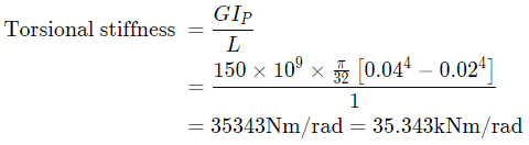
Q5: For an Oldham coupling used between two shafts, which among the following statements are correct? (2018 Set -1)
I. Torsional load is transferred along shaft axis.
II. A velocity ratio of 1:2 between shafts is obtained without using gears.
III. Bending load is transferred transverse to shaft axis.
IV. Rotation is transferred along shaft axis.
A. I and III
B. I and IV
C. II and III
D. II and IV
Ans: (b)
Sol:
Oldham coupling is used to connect two shafts which are not on the same axis means they are not aligned to the same axis
So,
(1) Torsional load is transferred along shaft axis as both shafts are rotating member.
So, that statement is correct.
(2) A velocity ratio 1:1 between shafts is obtained using gears.
So, this statement is wrong
(3) Bending load is not transferred transverse to shaft axis as there is no transverse load.
(4) Rotation is transferred along shaft axis
So, this statement is correct
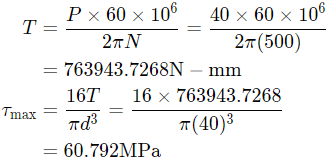
Q6: A motor driving a solid circular steel shaft transmits 40kW of power at 500 rpm. If the diameter of the shaft is 40 mm, the maximum shear stress in the shaft is ____MPa. (2017 Set - 1)
A. 60.7
B. 50.5
C. 55.25
D. 51.36
Ans: (a)
Sol:
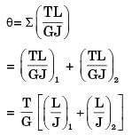
Q7: Two circular shafts made of the same material, one solid (S) and one hollow (H), have the same length and polar moment of inertia. Both are subjected to the same torque. Here, θs is the twist and τs is the maximum shear stress in the solid shaft, whereas θH is the twist and τH is the maximum shear stress in the hollow shaft. Which one of the following is TRUE? (2016 Set -3)
A. ( θs = θh and τs = τH
B. ( θs > θh and τs > τH
C. ( θs < θh and τs < τH
D. (θs = θh and τs < τH
Ans: (d)
Sol: 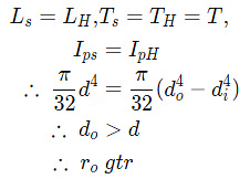
Angle of twist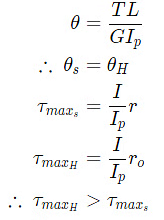
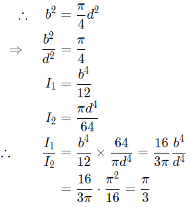
Q8: The cross-sections of two solid bars made of the same material are shown in the figure. The square cross-section has flexural (bending) rigidity I1, while the circular cross-section has flexural rigidity I2. Both sections have the same cross-sectional area. The ratio I1/I2 is (2016 Set -3)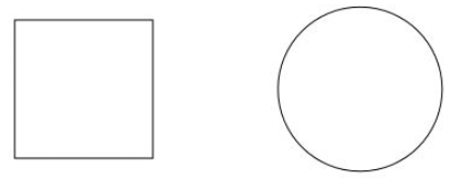 (a) 1/π
(b) 2/π
(c) π/3
(d) π/6
Ans: (c)
Sol: 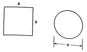
Q9: A simply supported beam of length 2L is subjected to a moment M at the mid-point x = 0 as shown in the figure. The deflection in the domain o≤x≤L is given by 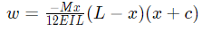
where E is the Young's modulus, I is the area moment of inertia and c is a constant (to be determined) (2016Set -2)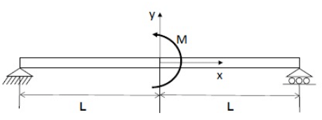
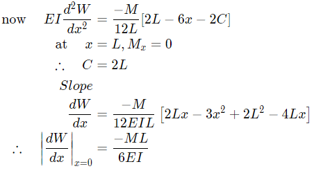
The slope at the center x = 0 is
(a) ML/(2EI)
(b) ML/(3EI)
(c) ML/(6EI)
(d) ML/(12EI)
Ans: (c)
Sol: 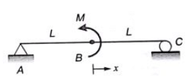
Equation of deflection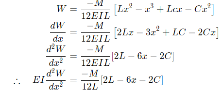
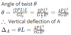
Q10: A rigid horizontal rod of length 2L is fixed to a circular cylinder of radius R as shown in the figure. Vertical forces of magnitude P are applied at the two ends as shown in the figure. The shear modulus for the cylinder is G and the Young's modulus is E. (2016 Set -2)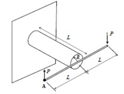
The vertical deflection at point A is
(a) 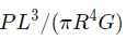
(b) 
(c) 
(d) 
Ans: (d)
Sol: 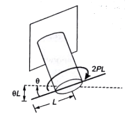
Try yourself: A cyiindrical elastic body subjected to pure torsion about its axis develops [1989]

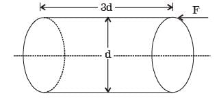
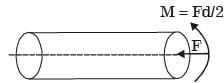
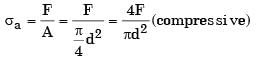
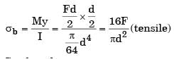
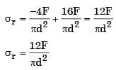
Try yourself: A circular rod of diameter d and length 3d is subjected to a compressive force F acting at the top point as shown below. Calculate the stress at the bottom most support point A [1993]


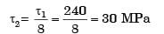
Try yourself: Maximum shear stress developed on the surface of a solid circular shaft under pure torsion is 240 MPa. If the shaft diameter is doubled then the maximum shear stress developed corresponding to the same torque will be [2003]
Try yourself: A solid circular shaft of 60mm diameter transmits a torque of 1600 Nm. The value of maximum shear stress developed is [2004]
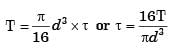
Try yourself: For a circular shaft of diameter d subjected to torque T, the maximum value of the shear stress is [2006]
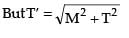
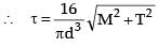
Try yourself: A solid circular shaft of diameter d is subjected to a combined bending moment M and torque, T. The material property to be used for designing the shaft using the relation  is
is


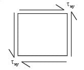
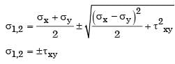
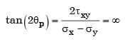
Try yourself: A shaft with a circular cross-section is subjected to pure twisting moment. The ratio of the maximum shear stress to the largest principal stress is [2016]
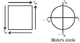 tmax = txy
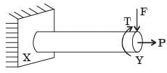
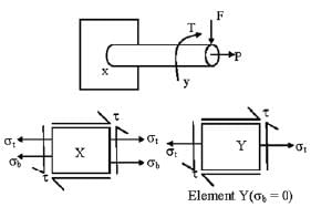
Try yourself: A machine element XY, fixed at end X, is subjected to an axial load P, transverse load F, and a twisting moment T at its free end Y. The most critical point from the strength point of view is [2016]
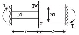
Try yourself: The compound shaft shown is built-in at the two ends. It is subjected to a twisting moment T at the middle. What is the ratio of the reaction torques T1, and T2 at the ends?

Try yourself: Two shafts A and B are made of the same material. The diameter of shaft B is twice that of shaft A. The ratio of power which can be transmitted by shaft A to that of shaft B is (If maximum shear stress remains the same) [1994]
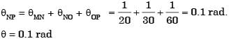
Try yourself: A torque of 1.0 Nm is transmitted through a stepped shaft as shown in figure. The torsional stiffnesses of individual sections of lengths M N, NO and OP are 20 Nm/rad, 30 Nm/rad and 60 Nm/rad respectively. The angular deflection between the ends M and P of the shaft is [2004]
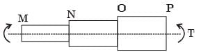

 = 20 NM/rad
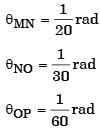
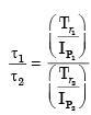
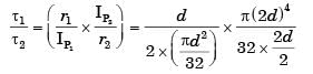
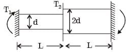
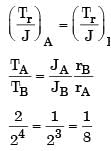
Try yourself: Two shafts AB and BC, of equal length and diameters d and 2d, are made of the same material. They are joined at B through a shaft coupling, while the ends A and C are built-in (cantilevered). A twisting moment T is applied to the coupling. If TA and Tc represent the twisting moments at the ends A and C, respectively, then [2005]
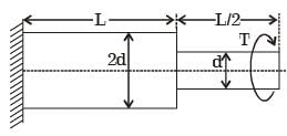
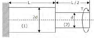
Try yourself: A torque T is applied at the free end of a stepped rod of circular cross-sections as shown in the figure. The shear modulus of the material of the rod is G. The expression for d to produce an angular twist q at the free end is [2011]


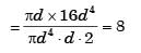
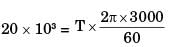
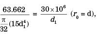
Try yourself: A hollow shaft (d0 = 2di where d0 and di are the outer and inner diameters respectively) needs to transmit 20 kW power at 3000 RPM. If the maximum permissible shear stress is 30 MPa, d0 is [2015]

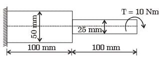
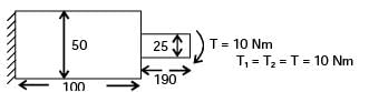
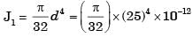
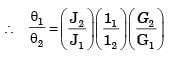
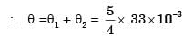
Try yourself: A stepped steel shaft shown below is subjected to 10 N-m torque. If the modulus of rigidity is 80 GPa, the strain energy in the shaft in N-mm is [2007]


FAQs on GATE Past Year Questions: Torsion of Shafts
| 1. What is torsion in mechanical engineering? |  |
| 2. Why is torsion important in mechanical engineering? | |
| 3. What are the factors affecting torsion in shafts? | |
| 4. How is torsional stress calculated in mechanical engineering? | |
| 5. What are the common failure modes in torsion of shafts? | |


