Chapter 8 - Power Electronics (Part - 2)

4. Inverters
Introduction
Inverters convert dc power into ac power at desired output voltage and frequency. Here the magnitude of output voltage is controlled through input dc voltage and the frequency is controlled through gating and of thyristors. Inverters can be broadly classified as voltage source and current source inverters. In voltage source inverter (VFI or VSl), dc source has negligible impedance Hence in case of VSl, output voltage waveform is affected by load and the output current waveform changes depending on the load. A current source inverter (CFl or CS1) has stiff dc current source at input terminal. Hence in case of CSI, output current waveform is not affected by load, rather the output voltage waveform may change depending upon the load.
Single Phase Voltage Source Inverter
Single Phase Half Bridge Inverter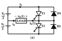
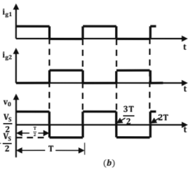 Single-phase half-bridge inverter.
Single Phase Full Bridge Inverters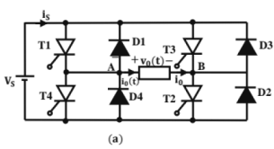
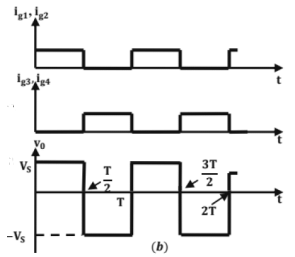 Single-phase full-bridge inverter
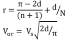
Fourier Analysis of Output Voltage for Single Phase Inverter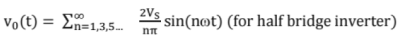
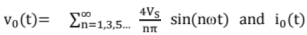
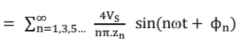
(for full bridge inverter)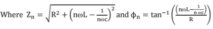
Three Phase Bridge Inverters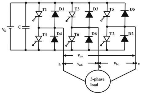 Three-phase bridge inverter using thyristors
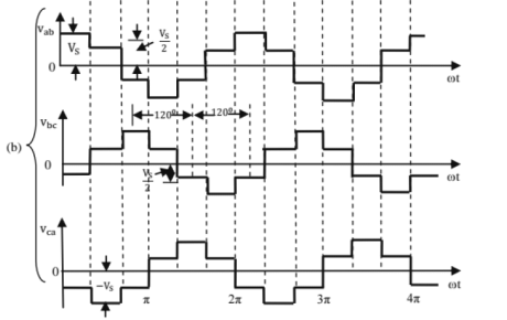
Three Phase 180° Mode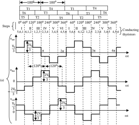
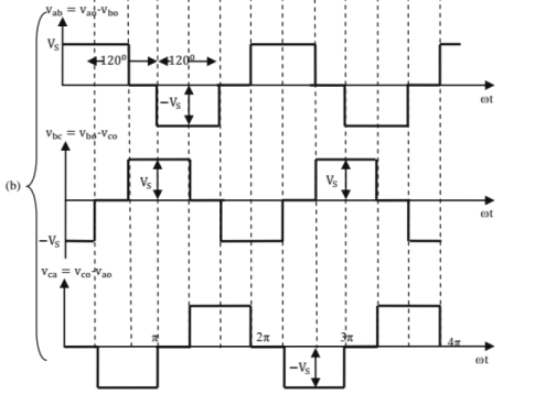 Voltage waveforms for 180° mode 3-phase VSI
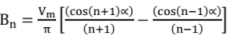
The fourier series expansion of line output voltage can be expressed as below,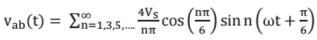
Similarly, Fourier series expansion of phase voltage can be expressed as,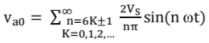
- rms value of line voltage = 0.8165 Vs
- rms value of fundamental line voltage = 0.7797VS
- rms value of phase voltage = 0.4714VS
- rms value of fundamental phase voltage = 0.4502V
Three Phase 120° Mode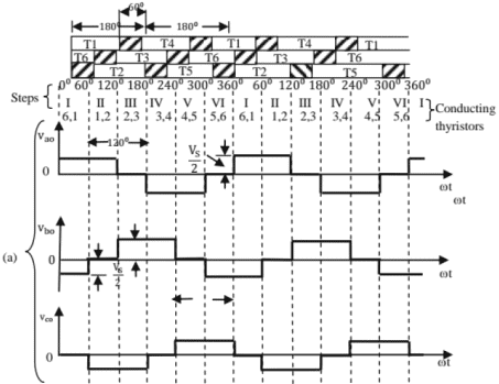
 Voltage waveforms for 120°mode six-step 3-phase VSI
Fourier expansion of output phase voltage waveforms are given below,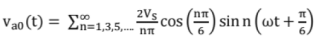
Fourier expansion of line voltage is given as,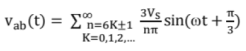
- rms value of phase voltage = 0.4082 VS
- rms value of fundamental phase voltage = 0.3898VS
- rms value of line voltage = 0.7071VS
- rms value of fundamental line voltage = 0.6752 VS
Voltage Control in Single Phase Inverters
External Control of Output Voltage
In this methodology, voltage control is obtained by external means, say by using phase controlled rectifiers, choppers, transformers etc.
AC Voltage Control
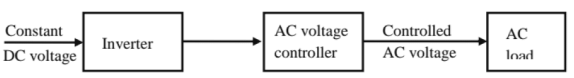 External control of AC output voltage
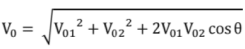
Series Inverters Control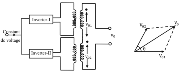 Series inverter control of two inverters
External Control of DC Input Voltage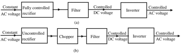
 External control of dc input voltage to inverter; (a), (b), (c) with ac source on the input (d) with dc source on the input
Internal Control of Inverters
This is mainly achieved by exercising control within the inverter. PWM inverters fall into this category. In this method, lower order harmonics can be eliminated by output voltage control and higher order harmonics can be easily filtered out.
Pulse Width Modulated Invertors
In this method, a fixed DC voltage is given to the inverter and a controlled AC output voltage is obtained by adjusting on and off periods of inverter components. Hence the method is termed as Tulse-Width Modulation (PWM) control". Thus PWM techniques are characterized by constant amplitude pulses. The advantages of PWM technique are the following,
- Output voltage control is achieved without additional components.
- With this method, lower order harmonics can be minimized along with the output voltage control. Also higher order harmonics can be easily filtered out
The main advantage of this method is that SCRs used must possess low turn-on and turn-off times. In PWM inverters, forced commutation is essential. Different PWM techniques are explained in detail below,
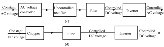
Single Pulse Modulation
In this method, a pulse of width of 2d is present in positive and negative half cycles, symmetrically about π/2 and 3π/2.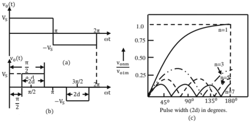
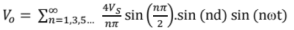
Kouries analysis of output voltage can be summarized as below;

Multiple Pulse Modulation (MPM)
MPM is an extension of SPM. In MPM, several equidistant pulses per half cycle are used.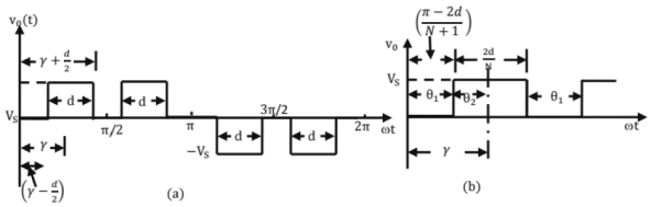 Symmetrical two-pulse modulation pertaining to MPM.
The Fouries analysis of the output voltage and different quantities related to the same are given below;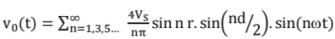
As numbers of pulses in half cycle increases, lower order harmonics are reduced.
Sinusoidal Pulse Modulation (sin M)
In sin M, several pulses per half cycle are present as in MPM. In sin M, pulse width is a sinusoidal function of angular position of pulse in a cycle as shown in figure below.
Reduction of Harmonics in Invertors Output Voltage
- Harmonic reduction by PWM
- Harmonic reduction by transformer connections
Current Source Invertors
In CSl, it's assumed that a constant current source is present at input terminals. Hence load current doesn't depend on nature of load, but output voltage waveform depends on nature of the load. A CSl doesn't require any feedback diodes.
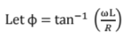
Single Phase CSl with R load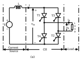
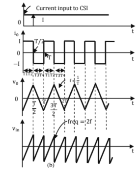 (a) Power circuit diagram and (b) wave forms for an ideal single -phase CSl
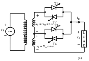
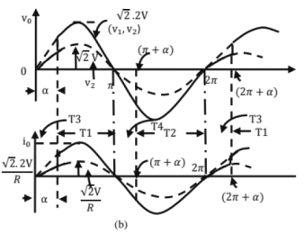
Single phase capacitor commentated CSl with R load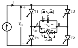 (a) Power circuit diagram of 1-Φ CSl with R load
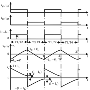
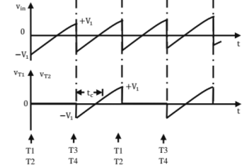 Voltage and current waveforms of CSI with R-load
5. AC Voltage regulators and Cycloconverters
Introduction to AC Voltage Controllers
AC voltage controllers are helpful to convert fixed alternating voltage to variable alternating voltage at the same frequency. The main disadvantage of these controllers is introduction of objectionable harmonics in supply currents, particularly at reduced voltages.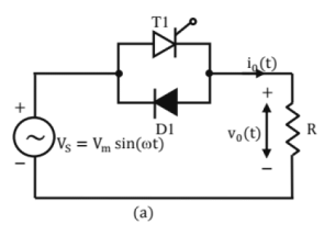
 Single-phase half-wave AC voltage controller (a) Power-circuit diagram and (b) voltage and current waveforms.
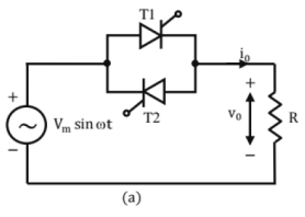
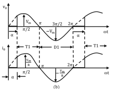
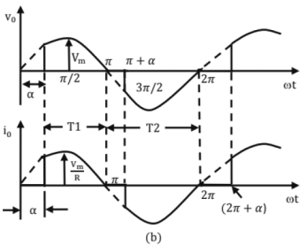 Single-phase full-wave AC voltage controller (a) Power-circuit diagram and (b) voltage and current waveform.
Integral Cycle Control
Integral cycle control refers to a technique in which supply is connected to load for integral number of cycles, m and disconnected for further integral number of cycles, n. By varying m and n, power delivered to load can be regulated.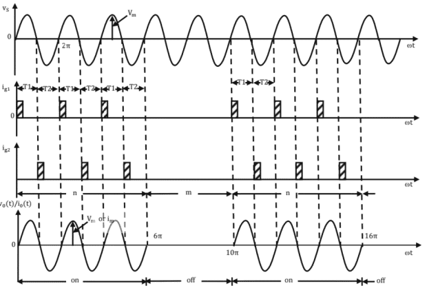 Waveforms pertaining to integral cycle contro
rms value of output voltage Vor = Vs√k where k = n/n + m) is duty cycle of AC voltage controller
rms value of load current,
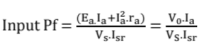
Power delivered to load
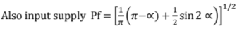
Input Pf = √R
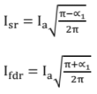
Average value of thyristor current,
rms value of thyristor current,
Integral cycle control relatively reduces lower harmonics as compared to phase controlled ac voltage controllers.
Single Phase Voltage Controllers with R-load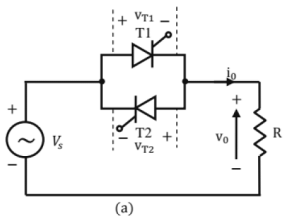
 (a) Single-phase AC voltage controller with Rlaod (b) votlage and current waveforms for figure, (a)


rms value of output voltage,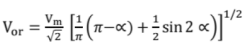
Average power delivered to load,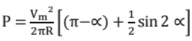
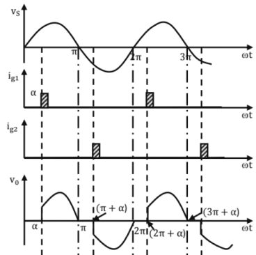
Single Phase Voltage Controller with R-L load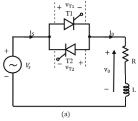
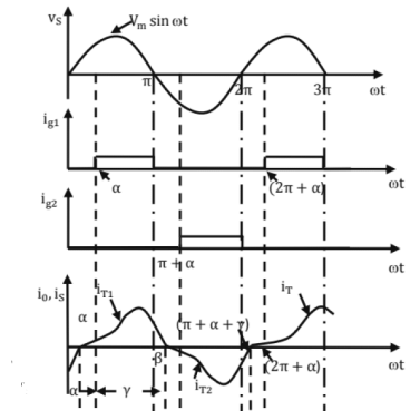
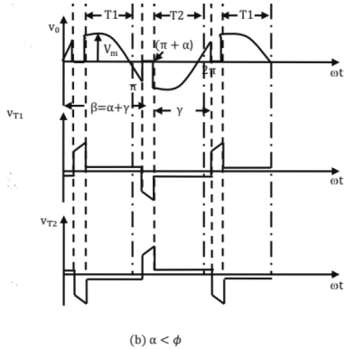
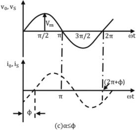
For ∝ ≥ Ф, V0 is controllable
For ∝ < Ф, thyristor T1 is reverse biased by voltage across T2. Hence T1 can not be triggered in positive half cycle. Same applies for T2 in negative half cycle
Two Stage Sequence Control of Voltage Controller
 Two-stage sequence controlled AC voltage controller (b) R load (c) RL load
Multi-Stage Sequence of Voltage Controller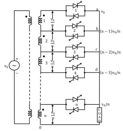 Multistage sequence control of AC votlage controllers
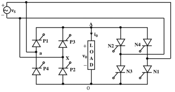
Here each transformer secondary is rated at Vs/n where Vs is source voltage. Depending on the required output voltage, required thyrsistor pairs are triggered at ωt = 0° and ωt = ∝. For output variation from 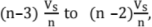 thyristor pair 4 is triggered at 0° and thyristor pair 3 is trigged at firing angle oc (0° < ∝ < 180°). Thus depending on required output voltage, by triggering the appropriate thyristor pairs, target output voltage can be achieved.
Introduction to Cydoconverters
Cydoconverter is a device which converts input power at one frequency to output power at a different frequency with one stage conversion.
Step-Down Cydoconverters
In step-down cydoconverters, output frequency, f0 is less than that of input frequency, fs; i.e f0 < fs.
Step-Up Cydoconverters
In step-up cydoconverters, output frequency, f0 is more than that of input frequency, fs; i.e fo > fs
Single Phase to Single Phase Circuit Step Up Cycloconverter
The cycloconvertors shown are of 2 types; mid-point and bridge cydoconverters.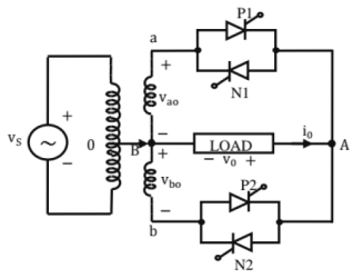
 Single-phase to single-phase cycloconverter rircuit (a) mid-point type and (b) bridge type
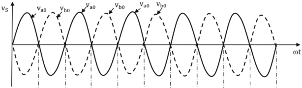
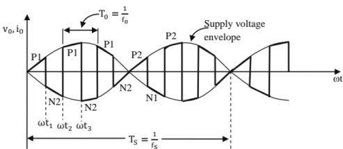 Waveforms for step-up cycloconverter
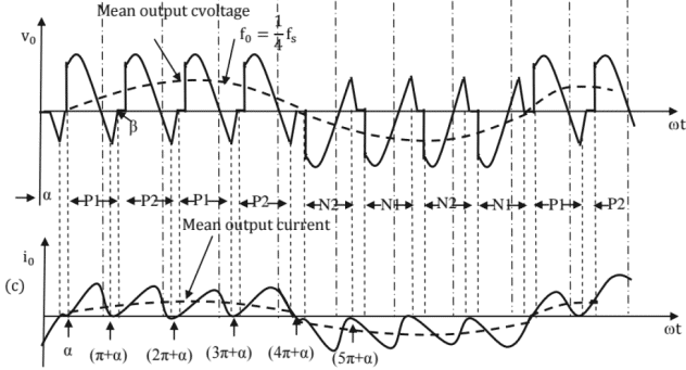 Voltage and current waveforms for step-down cycloconverter with discontinuous load current
6. Applications of Power Electronics
Introduction to Electric Drives
In many applications, electric motors supply power to a load, hence require a variable voltage or variable frequency control. The same can be achieved through power electronic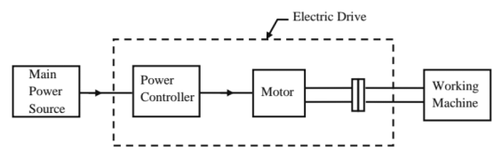 An electric drive system
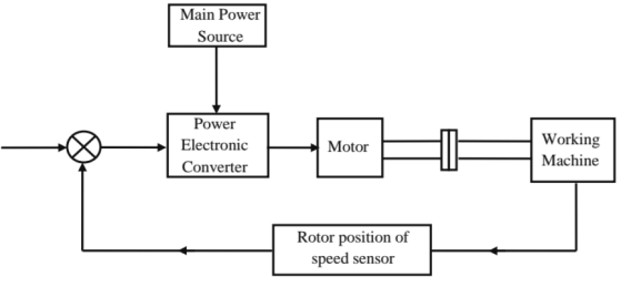 Block diagram of a modem electric drive system using power electronic converter.
Single Phase Half Wave Converter Drives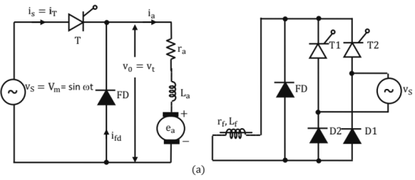
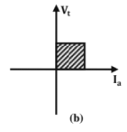
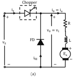
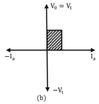
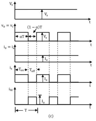
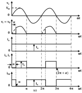 Single-phase half-wave converter drive (a) circuit diagram (b) quadrant diagram and (c) waveforms.
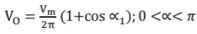
where ∝1 is firing angle of T.
Te = Km.Ia
where Km is motor constant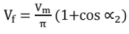
where ∝2 is firing angle of T1 and T2
Ea = Km.ωm
where ωm is speed of armature in rad/sec.
Single Phase Semi-Converter Drives
 Single-phase semiconverter drive (a) circuit diagram and (b) waveforms
Single Phase Full Converter Drives
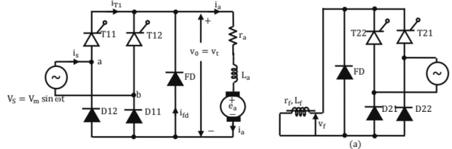
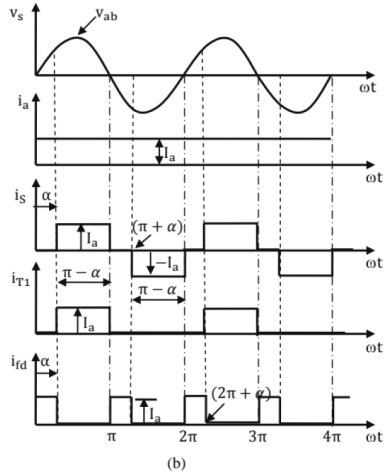
 Single-phase full converter drive (a) circuit diagram (b) two-quadrant diagram and (c) waveforms.
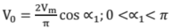
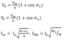
where ∝1 is firing angle of single phase full converter drive in armature circuit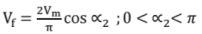
where ∝2 is firing angle of single phase full converter drive in field circuit.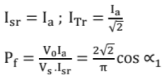
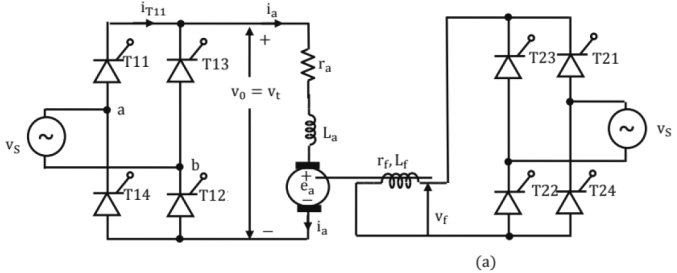
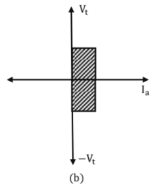
Single Phase Dual Converter Drive
A single phase dual converter obtained by connecting two full converters in anti-parallel and supplying power to a dc motor is shown in figure below.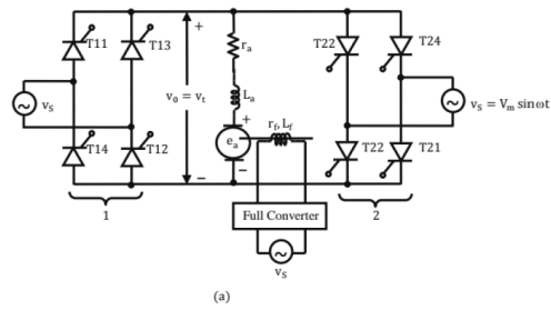
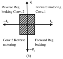
When converter 1 is in operation,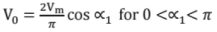
When converter 2 is in operation,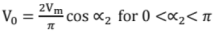
Also, ∝1 + ∝2 = π
Three Phase Drives
The three-phase dc drives may be subdivided as,
- Three phase half wave converter drive
- Three phase semiconductor drive
- Three phase full converter drive
- Three phase dual converter drive
Chopper Drives
When variable dc voltage is to be obtained from fixed dc voltage, dc chopper is an ideal a chopper is inserted between a fixed voltage dc source and dc motor armature. Figure
 D.C. Chopper for series motor drive (a) circuit diagram (b) quadrant diagram and (c) waveforms.
Power delivered to motor = Vt.la = ∝. Vs. la
Average source current = ∝. Ia
Vt = Ea + Ia(ra + rs) = Kmωm + Ia(ra + rs)
Where Km is motor constant
AC Drives
When AC voltage or frequency control of input voltage of a AC motor is required. The same can be achieved through AC voltage regulators or cydoconverters. AC drives have many advantages over DC drives like lighter weight for the same rating and low maintenance. Also AC drives can be classified as induction motor and synchronous motor drives. Also their operation can be summarized using appropriate motor equations and converter equations.


