Bridge Circuits: DC Bridge Circuits | Sensor & Industrial Instrumentation - Electronics and Communication Engineering (ECE) PDF Download
Dc Bridge Circuits
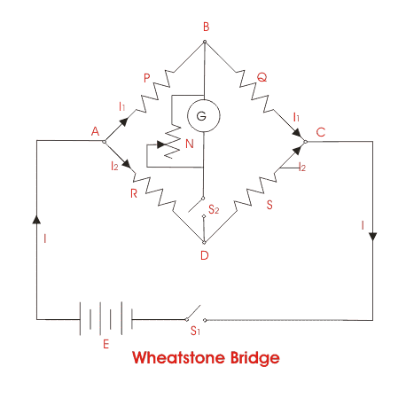
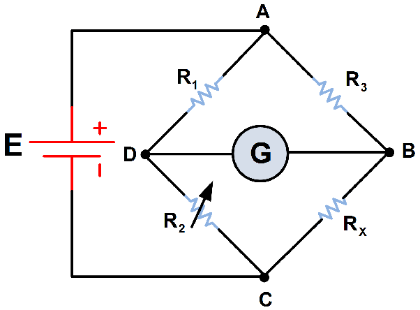
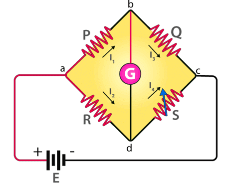
The simplest and most common bridge network is the DC Wheatstone bridge. The basic bridge is shown in Figure 3.10; this bridge is used in sensor applications, where small changes in resistance are to be measured. The basic bridge is modified for use in many other specific applications. In the basic bridge four resistors are connected Figure 3.9 Voltage divider.
 Figure 3.10 Circuit of a basic Wheatstone bridge.
in the form of a diamond with the supply and measuring instruments connected across the bridge as shown. When all the resistors are equal the bridge is balanced; that is, the bridge voltage at A and C are equal (E/2), and the voltmeter reads zero. Making one of the resistors a variable resistor the bridge can be balanced.
The voltage at point C referenced to D = E X R4/(R3 + R4)
The voltage at point A referenced to D = E X R2/(R1 + R2)
The voltage (V) between A and C = E R4/(R3 + R4) — E R2/(R1 + R2).....(3.17)
When the bridge is balanced V = 0,
and R3R2 = R1R4......(3.18)
It can be seen from (3.17) that if R1 is the resistance of a sensor whose change in value is being measured, the voltage at A will increase with respect to C as the resistance value decreases, so that the voltmeter will have a positive reading. The voltage (V) will change in proportion to small changes in the value of R1, making the bridge very sensitive to small changes in resistance. Resistive sensors such as strain gauges are temperature sensitive and are often configured with two elements that can be used in a bridge circuit to compensate for changes in resistance due to temperature changes, for instance, if R1 and R2 are the same type of sensing element. Then resistance of each element will change by an equal percentage with temperature, so that the bridge will remain balanced when the temperature changes. If R1 is now used to sense a variable, the voltmeter will only sense the change in R1 due to the change in the variable, not the change due to temperature [8].
➢ Lead Compensation
In many applications, the sensing resistor (R2) may be remote from a centrally located bridge. The resistance temperature device (RTD). In such cases, by using a two-lead connection as in Figure 3.10, adjusting the bridge resistor (R4) can zero out the resistance of the leads, but any change in lead resistance due to temperature will appear as a sensor value change. To correct this error, lead compensation can be used. This is achieved by using three interconnecting leads, labeled (a), (b), and (c) in Figure 3.11. A separate power lead (c) is used to supply R2. Consider point D of the bridge as now being at the junction of the supply and R2. The resistance of lead (b) is now a part of resistor R4 and the resistance of lead (a) is now a part of remote resistor R2. Since both leads have the same length with the same resistance and in the same environment, any changes in the resistance of the leads will cancel, keeping the bridge balanced. Figure 3.11 Circuit of a Wheatstone bridge with compensation for lead resistance used in remote sensing.
➢ Current Balanced Bridge
A current feedback loop can be used to automatically null the Wheatstone bridge, as shown in Figure 3.12. A low-value resistor R5 is connected in series with resistor R2. The output from the bridge is amplified and converted into a current I, which is fed through R5 to develop an offset voltage, keeping the bridge balanced. The current through R5 can then be monitored to measure any changes in R2. The bridge is balanced electronically to give a fast response time, and there are no null potentiometers to wear out. Initially, when the bridge is at null with zero current from the feedback loop:
R3 (R2 + R5) = R1 x R4
assume R2 changes to R2 + δR2.
Then, to rebalance the bridge;
R3 (R2 + δR2 + R5) - IR5 = R1 x R4
Subtracting the equations
δR2 = IR5/R3........(3.19)
showing a linear relationship between changes in the sensing resistor and the feedback current, with R5 and R3 having fixed values.
Due to the two features of high sensitivity to small changes in resistance and correction for temperature effects, bridges are extensively used in instrumentation with strain gauges, piezoresistive elements, and magnetoresistive elements. The voltmeter should have a high resistance, so that it does not load the bridge circuit. Bridges also can be used with ac supply voltages and ac meters, not only for the Figure 3.12 Current balanced Wheatstone bridge.
measurement of resistance, but also for the measurement of capacitance, inductance, or a combination of resistance, capacitance, and inductance [9].
|
26 videos|28 docs|29 tests
|


