Introduction of Thermocouples | Sensor & Industrial Instrumentation - Electronics and Communication Engineering (ECE) PDF Download
Thermocouples

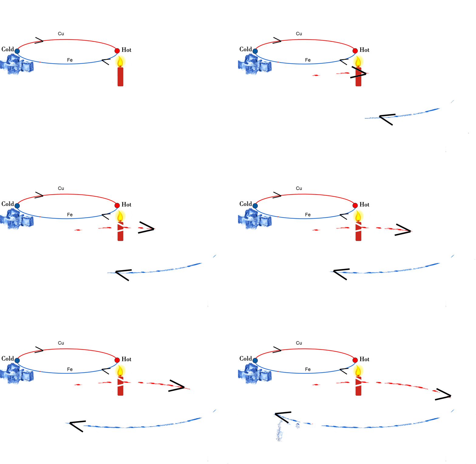
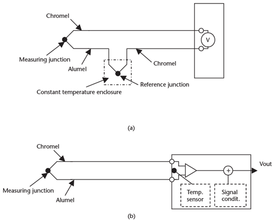
Thermocouples (T/C) are formed when two dissimilar metals are joined together to form a junction. Joining together the other ends of the dissimilar metals to form a second junction completes an electrical circuit. A current will flow in the circuit if the two junctions are at different temperatures. The current flowing is the result of the difference in electromotive force developed at the two junctions due to their temperature difference. The voltage difference between the two junctions is measured, and this difference is proportional to the temperature difference between the two junctions. Note that the thermocouple only can be used to measure temperature differences. However, if one junction is held at a reference temperature, then the voltage between the thermocouple junctions gives a measurement of the temperature of the second junction, as shown in Figure 10.6(a). An alternative method is to measure the temperature of the reference junction and apply a correction to the output signal, as shown in Figure 10.6(b). This method eliminates the need for constant temperature enclosures.
Three effects are associated with thermocouples:
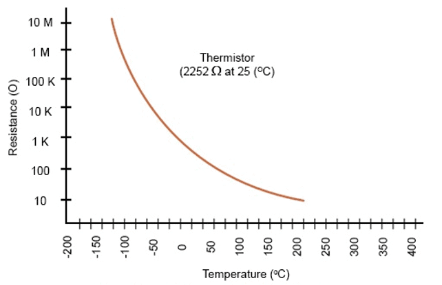
1. The Seebeck effect states that the voltage produced in a thermocouple is proportional to the temperature between the two junctions. Figure 10.5 Thermistor resistance temperature curve.
 Figure 10.6 (a) Thermocouple with the reference junction held at a fixed temperature, and (b) the temperature of the reference junction measured, and a correction applied to the output signal.
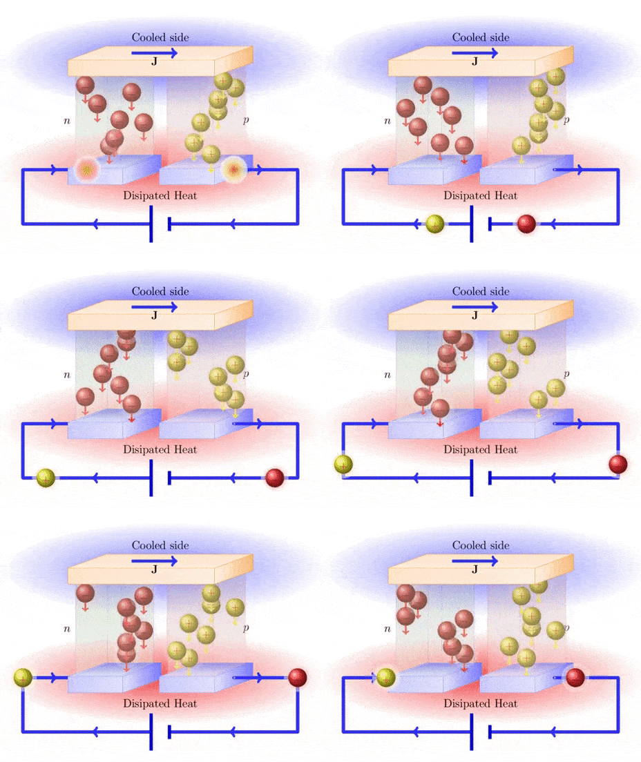
2. The Peltier effect states that if a current flows through a thermocouple, then one junction is heated (outputs energy), and the other junction is cooled (absorbs energy). 3. The Thompson effect states that when a current flows in a conductor along which there is a temperature difference, heat is produced or absorbed, depending upon the direction of the current and the variation of temperature.
In practice, the Seebeck voltage is the sum of the electromotive forces generated by the Peltier and Thompson effects. There are a number of laws to be observed in thermocouple circuits. First, the law of intermediate temperatures states that the thermoelectric effect depends only on the temperatures of the junctions, and is not affected by the temperatures along the leads. Second, the law of intermediate metals states that metals other than those making up the thermocouples can be used in the circuit, as long as their junctions are at the same temperature. Other types of metals can be used for interconnections, and tag strips can be used without adversely affecting the output voltage from the thermocouple. Letters designate the various types of thermocouples. Tables of the differential output voltages for different types of thermocouples are available from manufacturers’ thermocouple data sheets [4]. Table 10.7 lists some thermocouple materials and their Seebeck coefficients. The operating range of the thermocouple is reduced to the figures in parentheses if the given accuracy is required. For operation over the full temperature range, the
Table 10.7 Operating Ranges for Thermocouples and Seebeck Coefficients

accuracy would be reduced to approximately ±10% without linearization [5], or ±0.5% when compensation is used. Thermocouple tables are available from several sources such as:
- Vendors;
- NIST Monograph 125;
- ISA standards—ISA-MC96.1 – 1982.
There are three types of basic packaging for thermocouples: sealed in a ceramic bead, insulated in a plastic or glass extrusion, or metal sheathed. The metal sheath is normally stainless steel with magnesium oxide or aluminum oxide insulation. The sheath gives mechanical and chemical protection to the T/C. Sheathed T/C are available with the T/C welded to the sheath, insulated from the sheath, and exposed for high-speed response. These configurations are shown in Figure 10.7.
|
23 videos|24 docs|29 tests
|

|
Explore Courses for Electronics and Communication Engineering (ECE) exam
|

|


