Dynamic Analysis of Linkages | Theory of Machines (TOM) - Mechanical Engineering PDF Download

Introduction
If a number of bodies are connected & the motion of one body causes the predictable motion to the others, it is known as a mechanism.
- Kinematic Link or Element
Every part of a machine which is having some relative motion with respect to some other part is known as kinematic link or element.
It is necessary for the link to be a resistant body so that it is capable of transmitting power and motion from one element to the other element. - Rigid and Resistant Bodies
A body is said to be rigid if does not deform under the action of the load or the distance between any two points does not change.
(i) Resistant bodies are those which deform upto some extent under the action of external load.
Examples: A belt is rigid when subjected to tensile forces but belt-driven acts as a resistant body due to some deformation when they perform action. - Types of Links
(i) Rigid Links: Those links in which deformations are negligible.
Examples: Crank, connecting rod, piston, cylinder etc.
(ii) Flexible Links: Those links in which deformations occur but within permissible limits. Examples: Belt drive, Rope drive etc.
(iii) Fluid Links: When power is transmitted because of fluid pressure, then fluid behaves as a link.
Examples: Hydraulic Brakes, Hydraulic lift, Hydraulic Jack etc. - Types of Relative Motion
For the relative motion to occur, system must have two links. One link is the link whose motion is to be observed and another link is the link with respect to which the motion of first link is observed.
Constrained Motion
It is the desired motion which we want from the system. When we give an input and get the desired motion as output, then the motion is known as constrained motion.
- Completely Constrained Motion: When the motion is constrained by the system properties, then it is known as completely constrained motion. Motion between two elements of a pair is in definite direction irrespective of the direction of the force applied.
- Successfully Constrained Motion: When the motion is constrained by the surrounding properties, then it is known as successfully constrained motion. System may have more than one output but by some means of surrounding output restricted to constrained motion.
Examples: A shaft in a footstep bearing may rotates as well as reciprocates in step but due to load applied on the shaft it is constrained to rotation only.
A syringe can also rotate as well reciprocates but due to external applied load (human push) the valve of an IC engine is kept on the seat by the force of a spring and thus has successfully constrained motion. - Incompletely Constrained Motion (Unconstrained Motion): When for a given input more than one output is present then it is known as incompletely constrained or unconstrained motion. Motion between two elements of a pair is possible in more than one direction and depend upon the direction of the force applied.
For example: If the collar from completely constrained motion is removed then shaft can rotate as well as reciprocates which is independent of the other thus it can have two motion simultaneously which comes under unconstrained motion.
Kinematic Pair
Any connection of two links is always a joint or a pair but this pair will only be a kinematic pair when the relative motion between the links is a constrained motion.
Classification of Kinematic Pairs
- According to the type of Relative Motion
(i) Turning pair (Revolute pair/ Pin Joint): When one link has a turning or revolving motion relative to the other then they constitute a turning or revolving pair as shown is figure.
Examples: A circular shaft revolving inside a bearing is a turning pair.
All the hinge joint comes under Turning pair.
(ii) Sliding Pair (Prismatic Pair): If two links have a sliding motion relative to each other, they form a sliding pair.
Examples: A rectangular rod in a rectangular hole in a prism is a sliding pair
(iii) Rolling Pair: When the relative motion between two links is pure rolling (Rolling without slipping) then they form as rolling pair.
Examples: A rolling wheel on a flat surface is an example of rolling pair here translation is because of rotation thus translation is dependent upon the rolling.
Ball bearing is also an example of rolling pair in which ball rotates in provided recess.
(iv) Screw Pair (Helical Pair): If two mating links have a turning as well as sliding motion between them, they from a screw pair. Here also sliding motion depends upon the turning motion. This is achieved by cutting matching threads on the two links.
Examples: The lead screw and the nut of a lathe is a screw pair
(v) Spherical Pair [Ball and Socket Joint]: When the relative motion is 3-dimensional rotation then they form spherical pair (Spherical Motion). When one link in the form of a sphere turns inside a fixed link of spherical shape, then it is a spherical pair.
Examples: The ball and socket joint is an example of spherical pair.
Side mirror of car is also an example of spherical pair. - According to the type of Contact between the links
(i) Lower Pair: A pair of links which is having surface or area contact between connecting link is known as a lower pair.
Examples: Nut turning on a screw, shaft rotating in a bearing, all pairs of a slider-crank mechanism, universal joint, etc.
(ii) Higher Pair: When two connecting pair has a point or line contact between the links, then it is known as a higher pair.
Examples: Wheel rolling on a surface cam and follower pair, tooth gears, ball and roller bearing, etc.
(iii) Wrapping Pair: When one link is wrapped over other link then it comes under wrapping contact. In wrapping contact pair, multiple points one surface comes into contact with the other surface thus it similar to point contact and nearer to higher pair.
Example: Belt wrapped over pulley. - According to the type of Closure or Contact between the links
(i) Self-Closed Pair [Closed Pair]: When the connection between two links is Permanent without any external support.
When the elements of a pair are held together mechanically, it is known as closed pair.
All the lower pairs and some of the higher pair are closed pair.
(ii) Forced Closed Pair [Open Pair]: When the connection between two links is not permanent but it is made to contact by applying some external load is known as open pair.
The link will be in contact until and unless the force is applied on the body as the load is removed contact between them will not be anymore.
In this, the links are not held together mechanically.
Examples: Automatic Door Closures, Automatic Clutch operating
Kinematic Chain
If all the links are connected in such a way that the first link is connected to the last link in order to get the closed chain and the relative motions in this closed chain are constrained, then such a closed chain is kinematic chain.
Degrees of Freedom [Mobility]
- The minimum number of independent variables required to define the position or motion of the system is known as degrees of freedom of the system.
- It can also be defined as the number of possible outputs from a single input is known as Degree of Freedom.
- Degree of Freedom (DOF) = 6 – Restraints
The number of restraints can never be zero (joint is disconnected) or six (joint becomes solid).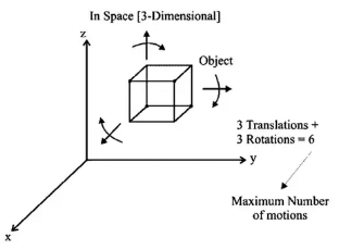 Maximum number of motions possible of an object in 3D
Number of restraints for different pair
- Turning Pair: Restraints = 5; DOF = 6 – 5 = 1
- Lower Pair: DOF = 1 (expect spherical pair; DOF = 3)
- Higher Pair: DOF = 2
- Degrees of Freedom of 2-Dimensional Planar Mechanisms
For a 2 D mechanism
Maximum motions = 3 [2 Translations + 1 Rotation]
If Number of links = l
Number of binary joints = j; Number of Higher pairs = h
Therefore, Degrees of Freedom of any planar mechanism can be given by
F = 3(l – 1) – 2j – h [KUTZBACK’S EQUATION]
When there is redundant motion is present in the system
Then,
F = 3(l – 1) – 2j – h - Fr
[where Fr is number of redundant motions which are not the part of a mechanism]
(i) Redundant motions: The motion which does not affect the output of the mechanism.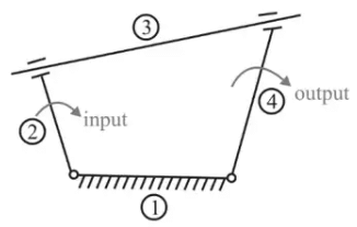 Redundant motionHere, link 3 is a circular rod which can rotate in the groove, but while rotating it is not affecting the system, thus the motion of the third link is redundant.
(ii) Redundant Link: A link which do not introduce any extra constraint. Such links are known as redundant link.
Or
“If the presence of any link does not affect the output of the system then it is known as redundant link.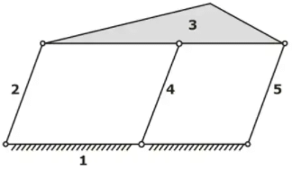 Degree of Freedom of above mechanism remains same even after the removal of 4th link. Hence, link 4 is a redundant link.Redundant link
 - Linkage Mechanism and Structure: A linkage is obtained if one of the links of a kinematic chain is fixed.
If motion of any of the moveable links results in definite motions of the others, the linkage is known as a mechanism. - Structure/Frame: Structure is a mechanism; whose degree of freedom is zero.
No relative motion is possible in case of structure/frame. - Super Structure: Mechanisms whose degree of freedom is less than zero are known as super structure.
It is also known as indeterminate structure.
Type of Chains
- Kinematic Chain: Mechanism whose degree of freedom is equal to one.
- Unconstrained Chain: Mechanism whose degree of freedom is more than one.
Note: Degrees of Freedom is the number of inputs required to obtain constrained output.
Grubler’s Equation
It is a special case of mechanism
Those mechanisms, where degree of freedom is one and consisting of only lower pairs, DOF = 1 and h = 0
As per the kutzabck’s equation.
DOF = 3(l - 1) - 2j - h
1 = 3l – 3 - 2j - 0
3l - 2j - 4 = 0
From the above equation
(3l) must always be even, so “l” must be always even. If l is equal to 2, then the chain will not be a closed chain.
Next higher even number is 4
Hence, to obtain the mechanism which provides constrained motion and consists of only lower pairs, the minimum number of links required are four.
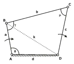
Four Bar Mechanism
- Simple mechanism which consists of four links connected by four turning pairs.
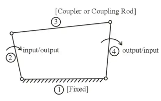 Four-Bar Mechanismfor a four-bar mechanism to be practically possible, when the sum of the three link is greater than the fourth link.
- Inversions
When different links are fixed, then we obtain different mechanisms and these different mechanisms are called inversions.
If number of links = l, Then
Number of inversions < I
Inversions of Four Bar Mechanism
Number of links in four bar mechanism = 4
Therefore, number of inversions < 4
(i) DOUBLE CRANK MECHANISM
(ii) CRANK - ROCKER MECHANISM
(iii) DOUBLE ROCKER or ROCKER - ROCKER MECHANISM - Grashof’s Law
For the continuous relative motion between the number of links in a four bar mechanism, the summation of length of the shortest (s) and longest links (l) should not be greater than the summation of the other two (p and q) links.
Hence, for the continuous relative motion,
(s + I) ≤ (p + q)
CASE I: When summation of lengths of shortest and longest links is lesser than summation of lengths of other two links:
(s + l) (p + q); Grashof’s Law is satisfied
(i) If shortest link is fixed: DOUBLE CRANK MECHANISM
(ii) If shortest link is adjacent to the fixed link: CRANK ROCKER MECHANISM
(iii) If shortest link is made coupler or coupling rod: DOUBLE ROCKER MECHANISM
Case II: When summation of lengths of shortest and longest links is equal to summation of lengths of other two links:
(s + l) = (p + q);
Grashof’s Law is satisfied.
(i) Not having pair of equal links (e.g. 3, 6, 5, 4)
3 + 6 = 4 + 5
(ii) If shortest link is fixed: DOUBLE CRANK MECHANISM
(iii) If shortest link is adjacent to the fixed link: CRANK ROCKER MECHANISM
(iv) If shortest link is made coupler or coupling rod: DOUBLE ROCKER MECHANISM
(v) Having pair of equal links (e.g. 3, 3, 5, 5)
Case I: If similar links are opposite to each other [PARALLELOGRAM LINKAGE]
If in a four-bar linkage, two opposite links are parallel and equal in length, then any of the links can be fixed and the links adjacent to the fixed link will act as two cranks.
Case II: If similar links are adjacent to each other [DELTOID LINKAGE]
(i) If shortest link is fixed: DOUBLE CRANK MECHANISM
(ii) If longest link is fixed: CRANK ROCKER MECHANISM
Case III: When summation of lengths of shortest and longest links is more than the summation of lengths of other two links,
(s + l) (p + q)
Grashof’s law is not satisfied
In all such arrangements, DOUBLE ROCKER MECHANISM will be obtained. - Transmission Angle
The angle between the output link and the coupler is known as transmission angle. It is designated by μ
 μ will be maximum when θ is 180°
μ will be minimum when θ is 0°
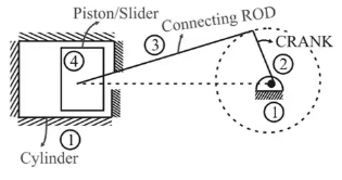
Single Slider Crank Mechanism
- Mechanism which consists of four links connected by three turning pairs and one sliding pair.
1. Crank is Fixed
- Whitworth Quick Return Motion Mechanism
- Rotary Internal Combustion Engine (Gnome Engine)
2. Connecting Rod is Fixed
- Crank and Slotted lever Quick Return Motion Mechanism
- Oscillating Cylinder Engine Mechanism
3. Piston/Slider Is Fixed
- Hand Pump (Pendulum Pump/Bull Engine)
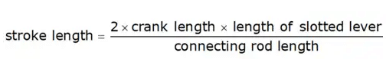
Crank and Slotted Lever Quick Return Motion Mechanism
- It is an inversion of single slider crank mechanism in which connecting rod is fixed.
It is a type of crank rocker mechanism.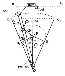 Crank and slotted lever quick return motion mechanism
β = cutting stroke angle
α = return stroke angle
α + β = 360°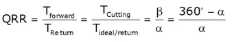
QRR = Quick return ratio
QRR > 1
Double Slider Crank Chain
Chain which consists four links connected by two turning pairs and two sliding pairs is known as double slider crank chain & by fixing different-different links the mechanisms which are obtained is known as Double slider crank mechanism. Double Slider Crank Chain
- Slotted bar is fixed: elliptical trammels
- One of the sliders is fixed: scotch-yoke mechanism
- Link connecting sliders is fixed: Oldham’s coupling.
Mechanical Advantage (M.A.) Of The Mechanism
The mechanical advantage (MA) of a mechanism is defined as the ratio of the output force or torque to the input force or torque at any instant.
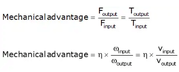
Toggle Position
Toggle position in a mechanism is defined as that position when the angle between the input link and coupler link is 180.
In such a situation, the velocity of the output link becomes zero and hence, the mechanical advantage becomes infinite.
|
87 videos|76 docs|29 tests
|
FAQs on Dynamic Analysis of Linkages - Theory of Machines (TOM) - Mechanical Engineering
| 1. What is dynamic analysis of linkages in mechanical engineering? |  |
| 2. What are the key components of dynamic analysis in linkages? | |
| 3. How is dynamic analysis different from static analysis in linkages? | |
| 4. What are some applications of dynamic analysis in mechanical engineering? | |
| 5. What are the challenges in performing dynamic analysis of linkages? | |


Extra Questions
,Exam
,Dynamic Analysis of Linkages | Theory of Machines (TOM) - Mechanical Engineering
,Important questions
,Summary
,Sample Paper
,MCQs
,Semester Notes
,Free
,ppt
,shortcuts and tricks
,mock tests for examination
,Dynamic Analysis of Linkages | Theory of Machines (TOM) - Mechanical Engineering
,video lectures
,practice quizzes
,Objective type Questions
,study material
,past year papers
,Viva Questions
,Dynamic Analysis of Linkages | Theory of Machines (TOM) - Mechanical Engineering
,Previous Year Questions with Solutions
;


Dynamic Analysis of Linkages Free PDF Download
Importance of Dynamic Analysis of Linkages
Dynamic Analysis of Linkages Notes
Dynamic Analysis of Linkages Mechanical Engineering Questions
Study Dynamic Analysis of Linkages on the App
|
© EduRev
|
Education Revolution
|


|


