Governors - Mechanical Engineering PDF Download
| Table of contents |

|
| Introduction |

|
| Governor Terminology |

|
| Controlling force |

|
| Types of Governor |

|
| Sensitiveness of Governor |

|
Introduction
- The function of a governor is to regulate the mean speed of an engine, when there are variations in the load e.g. when the load on an engine increases, its speed decreases, therefore it becomes necessary to increase the supply of working fluid and governor ensures to supply this excess fuel to the engine, hence maintaining the mean speed.
- The function of a governor is to maintain the speed of an engine within specified limits.
Types of Governors
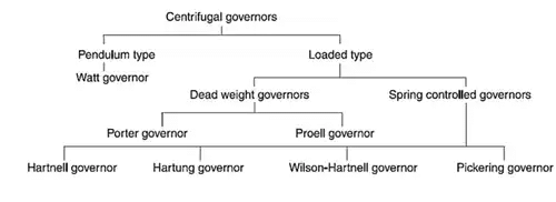
- Watt Governor (Simple Conical Governor)
(i) The simplest form of a centrifugal governor is Watt governor. It is basically a conical pendulum with links attached to a sleeve of negligible mass.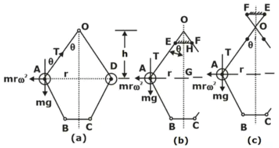 mω2r x h = mg x rSchematic and Dynamics of Watt Governor
h = g/ω2 = 895/N2 (N is in rpm) - Porter Governor
(i) The Porter governor is a modification of the Watt’s governor, with central dead load attached to the sleeve.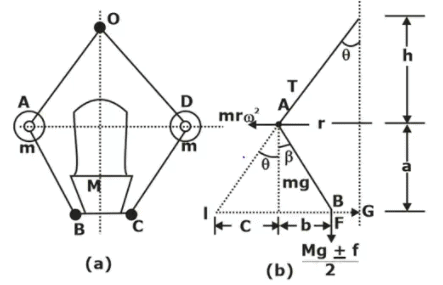 Schematic and Dynamics of Porter Governor
Case 1: When β = θ → k = 1
Case 2: f = 0
Case 3: When β = θ & f = 0
- Proell Governor
(i) A Porter governor is known as a Proell governor if the two balls are fixed on the upward extensions of the lower links which are in the form of bent links BAE and CDF as shown in Figure.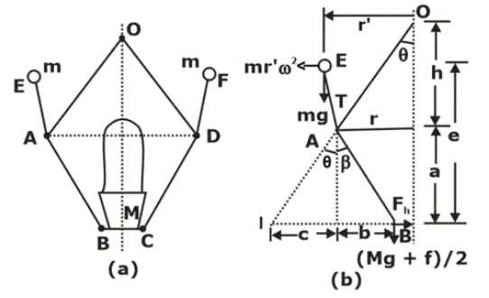 Schematic and Dynamics of Proell governor
Special cases: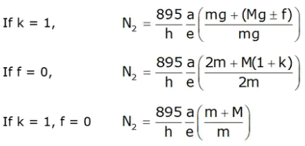
- Hartnell Governor (Spring Controlled Governors)
(i) It is a spring-controlled governor in which balls are mounted on the bell crank lever and sleeve is loaded by spring force as shown in Fig.
(ii) Initially, the spring is fitted in compression so that a force is applied to the sleeve.
(iii) Two bell-crank levers, each carrying a mass at one end and a roller at the other, are pivoted to a pair of arms which rotate with the spindle. The rollers fit into a groove in the sleeve.
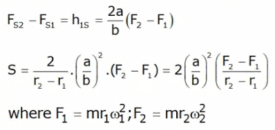
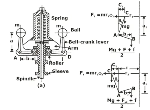 Schematic and Dynamic of Hartnell GovernorFs = spring force

Let s = stiffness of the spring
h1 = movement of the sleeve,
Governor Terminology
- Stability
(i) A governor is said to be stable if with the increase in the speed, radius of rotation of balls increases.
(ii) A stable governor brings the speed of the engine to the required value and there is not much hunting. - Sensitiveness of a Governor
(i) A governor is said to be sensitive when there is larger displacement of the sleeve due to a fractional change in speed.
(ii) Sensitiveness of the governor shall be defined as the ratio of speed range to the mean speed.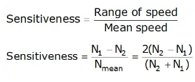
- Isochronous Governor
(i) A governor is said to be isochronous when the equilibrium speed is constant (i.e. range of speed is zero) for all radii of rotation of the balls within the working range, neglecting friction. - Hunting
(i) An excessive fast to & fro motion of the sleeve between the stoppers is known as hunting. It is the worst situation & will introduce noise and vibration.
(ii) Hunting takes place in oversensitive governor.
(iii) Higher the sensitiveness of the governor, the problem of hunting becomes more acute.
Controlling force
When the balls of a governor rotate in their circular path, the centrifugal force on each ball tends to move it outwards which is resisted by an equal and opposite force acting radially inwards and is known as the controlling force (CF).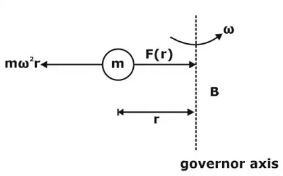 Controlling force
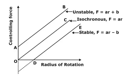 Graphical representation of various spring-controlled governors
Controlling force is equal and opposite to the centrifugal force and acts readily inward. It is supplied by
- Gravity of mass of ball in case of watt governor.
- Gravity of mass of ball and dead weight of sleeve in case of porter and porter governor.
- Gravity of ball masses and spring force in hartnell and hartung governs.
- Controlling force curve for spring loaded governor.
Controlling force =
For a Porter governor
Function/General Working
- The function of a Governor is to maintain speed of an engine within specified limits whenever there is a variation of load.
- If the load on the shaft increases, the speed of the engine decrease unless the supply of fuel is increased by opening the throttle valve. On the other hand, if the load on the shaft decreases, the speed of the engine increases unless the fuel supply is decreased by closing the valve sufficient to slow the engine to its original speed. The throttle valve is operated by the governor through a mechanism for the purpose.
Types of Governor
1. Centrifugal Governor
- Its action depends on the change of speed and centrifugal effect produced by the masses, known as governor balls, which rotate at a distance from the axis of rotation.
- The action of the governor depends upon the centrifugal effects produced by the masses of the two balls. With the increase in the speed, the balls tend to rotate at a greater radius from the axis. This causes the sleeve to slide up on the spindle and this movement of the sleeve in communicated to the throttle through a bell crank lever. This closes the throttle valve to the required extent. When the speed decreases, the balls rotate at a smaller radius and the valve is opened according to the requirement.
2. Inertia Governor
- The positions of the balls are affected by the forces set up by an angular acceleration or deceleration of the given spindle, in addition to centrifugal forces on the balls.
- The balls are operated by the rate of change of speed in case of inertia governors.
Hence the response of inertia governors is faster than that of centrifugal type.
Let, r = Radial distance OG
v = Tangential velocity of G =ωr
ω = Angular velocity of disc
Centrifugal force of the rotating mass,
F = (radially outwards) mrω2
If the engine shaft is accelerated due to increase in speed, the ball mass does not get accelerated at the same amount on account of its inertia, the inertia force being equal to
Types of Centrifugal Governor
There are two type of centrifugal governor
(i) Pendulum type – Watt governor
(ii) Loaded type
Watt Governor
Assumption
- Link is massless.
- Sleeve is frictionless.
Let, m = Mass of each ball
h = Height of each ball
w = Weight of each ball
ω = Angular velocity of the balls, arms and the sleeve
T = Tension in the arm
r = Radial distance of ball-centre from spindle-axis
- The mass m at A is in static equilibrium under the action of
Weight w (= mg)
centrifugal force mrω2
Tension T in the upper link
Thus equilibrium of the mass gives, height of governor
Let, m = mass of each ball
h = height of governor
w = weight of each ball (= mg)
ω = angular velocity of the balls, arms and the sleeve
T = tension in the arm
r = radial distance of ball-centre from spindle-axis
N = Speed of rotation (rpm)
PORTER GOVERNOR
If the sleeve of a Watt governor is loaded with a heavy mass, it becomes a Porter governor.
Let, M = Mass of the sleeve
m = Mass of each ball
f = Force of friction at the sleeve
h = Height of the governor
r = Distance of the centre of each ball from axis of rotation
q = Angle between arm and spindle axis
b = Angle between link and spindle axis
The instantaneous centre of rotation of the link AB is at I for the given configuration of the governor. It is because the motion of its two points A and B relative to the link is know. The point A oscillates about the point O and B moves in a vertical direction parallel to the axis. Lines perpendicular to the direction of these motions locates the point I.
Considering the equilibrium of the left-hand half of the governor and taking moments about I,
By solving it, we get
If k = 1, f = 0
PROELL GOVERNOR
- A Proell Governor is known as a Proell Governor if the two balls (masses) are fixed on the upward extensions of the lower links which are in the form of bent links BAE and CDF shown in the below figure.
Considering the equilibrium of the link BAE which is under the action
The weight of the ball, mg
The centrifugal force, mr'ω2
The tension in the link AO
The horizontal reaction of the sleeve
The weight of sleeve and friction
As before, I is the instantaneous centre of the link BAE
Taking moments about I,
In the position when AE is vertical, i.e., m neglecting its obliquity
By solving above equation, we get
If k = 1, f = 0
HARTNELL GOVERNOR
In this governor, ball are controlled by a spring.
As the speed increases and the balls move away from the spindle axis, the bellcrank levers move on the pivot and lift the sleeve against the spring force. If the speed decreases, the sleeve moves downwards. The movement of the sleeve is communicated to the throttle of the engine. The spring force can be adjusted with
the help of a screw cap.
Let, Centrifugal force (F) = mrω2
Fs = Spring force
Taking moments about the fulcrum A,
Neglect obliquity of the arm in that case,
Now, from above equation
Also
Sensitiveness of Governor
• A governor is said to be sensitive when it readily responds to a small change of speed.
Sensitiveness =
When, N = Mean speed
N1 = Minimum speed corresponding to full load conditions
N2 = Maximum speed corresponding to no-load conditions
Hunting
Sensitiveness of a governor is a desirable quality. However, if a governor is too sensitive, it may fluctuate continuously. This phenomenon of fluctuation is pronounced as hunting.
Isochronism
A governor with sensitivity equal to infinity is treated as isochronous governor. For all position of sleeves, governor has same speed.
Stability
A governor is said to be stable if it brings the speed of the engine to the required value and there is not much hunting. The ball masses, occupy a definite position for each speed of the engine within the working range. The stability and the sensitivity are two opposite characteristics.
Effort of Governor
The effort of the governor is the mean force acting on the sleeve to raise or lower it for a given change of speed. At constant speed, the governor is in equilibrium and the resultant force acting on the sleeve is zero. However, when the speed of the governor increases or decreases, a force is exerted on the sleeve which tends to move it. When the sleeve occupies a new steady position, the resultant force acting on it again becomes zero.
Power of Governor
The power of a governor is the work done at the sleeve for a given percentage change of speed.
Power = Effort of governor × displacement
FAQs on Governors - Mechanical Engineering
| 1. What is the role of a governor in mechanical engineering? |  |
| 2. What is the controlling force in a governor? |  |
| 3. How many types of governors are there in mechanical engineering? |  |
| 4. What is the sensitiveness of a governor? |  |
| 5. How do governors work to regulate the speed of a machine? |  |


