Metal Casting Processes | Manufacturing Engineering - Mechanical Engineering PDF Download

Casting
Casting is one of the oldest manufacturing processes, and even today is the first step in manufacturing most products.
“In a casting process, the liquid molten metal is poured into the mould cavity having the similar shape of the casting to be produced, & left free it to solidify and after solidification, the casting can be taken out by breaking the mould".
A Pattern is the replica of the part to be cast (to be produced) and is used to prepare the mould cavity. Patterns are made of either wood or metal.
An assembly of two or more metal blocks, or bonded refractory particles (sand) consisting of a primary cavity is called Mould.
- Molten metal can flow into any small section in the mould cavity, hence any intricate shape can be produced.
- Practically any material can be casted.
- Tools required are very simple and inexpensive.
- Due to same cooling rate from all directions, the uniform mechanical properties can be obtained.
- With normal sand-casting process, the dimensional accuracies and surface finish is poor.
- Defects are inevitable.
- Sand casting is labour intensive.
The sequence of steps involved in casting are:
- Preparation of pattern
- Preparation of mould
- The Gating system (Design)
- Design of Riser
- Melt the metal whose casting is to be formed
- Pouring of molten metal
- Solidification
- Fettling
- Finishing
- Testing
A pattern is always slightly different from the final job to be Produced. This difference in dimensions is referred as the pattern allowance.
Pattern size = casting size ± allowances
1. Liquid Shrinkage
2. Solidification Shrinkage
3. Solid Shrinkage
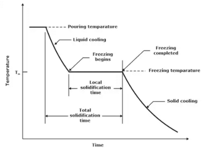 Cooling curve for a pure metal during castingSolid shrinkage,
Shrinkage allowance to be provided on pattern
δL = LαΔT = Lα(TF - To
Where, δL=Change in dimension
L = Initial dimension of component
α = Coefficient of thermal expansion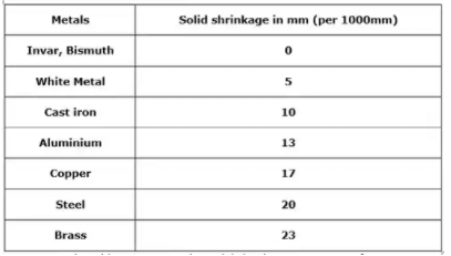
Machining Allowance
The Typical machining allowances for sand castings range = 1.5 mm and 3 mm
Draft or Taper Allowance
A draft facilitates easy withdrawal of the pattern. The value of the draft is between 0.5° and 2°.
Shake Allowance
Allowance provided on the pattern to compensate this increase in size of the casting is known as shaking Allowance.
Distortion Allowances
To avoid the distortion, the shape of pattern itself should be given a distortion of equal amount in the opposite direction of the likely distortion direction so that final product will come in true shape known as distortion allowance.
Types of Patterns
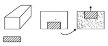
(i) Solid or single piece pattern: It is the simplest pattern in which pattern is made up of single piece and it does not contain any attached part.
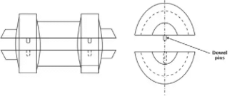
 (ii) Split Pattern or Two-Piece Pattern: This pattern is used mainly for intricate castings.
 (iii) Match plate pattern: Production efficiency and dimensional accuracy is improved by this method.
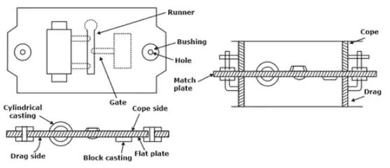
(iv) Cope and drag pawn: The cope and drag halves of a split pattern are separately mounted on two match plates. Thus, the cope and the drag flasks are made separately and brought together (with accurate relative location) to produce the complete mould.
(v) Gated Pattern: This is simply one or more than one loose pattern with attached gates and runners and provides a channel through which the molten metal can flow from the pouring sprue to the mould cavity.
(vi) Loose Piece Pattern: In this pattern, the parts of the pattern will overhang such that It is not possible to remove the pattern from the sand, in any direction, even if parted.
(vii) Sweep pattern: Sweep patten is used to generate surfaces of revolution in large castings, and to prepare moulds & it is done by sweeping the complete casting by means of a plane.
(viii) Follow board pattern: It is used for castings where having structurally weak portions and are likely to break under the force of ramming if not supported.
(ix) Skeleton Pattern: This type of pattern is useful generally for very large castings required in small quantities where large expense on complete wooden pattern is not justified.
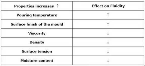
Effect of moisture content on properties of moulding sand:
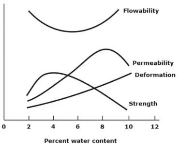
Properties of Moulding Sand
(i) Permeability: It is the ability of moulding sand to allow the air to escape”. It is important to remove the gases because the gases trapped inside the casting cause defects.
The permeability number is given by:
Pn = VH/PAT
Where,
V= volume of air in cm3
H = height of the sand specimen in cm
P = air pressure, gm/cm2
A = Cross section area of sand specimen in cm2
T = time in minutes,
Pn = 50.127/T
Where, T is in minute
(ii) Strength: Measurement of strength of moulding sands can be carried out on the universal sand strength testing machine.
(iii) Green Strength: The strength of the moist moulding sand is termed as green sand.
(iv) Dry Strength: When the moisture in the moulding sand is completely removed, it is called dry sand.
(v) Hot Strength: The strength of the sand that is required to hold the shape of the mould cavity is called hot strength.
(vi) Refractoriness: The ability of with standing higher temperature of the molten metal so that it does not cause fusion i.e. without losing its strength and hardness is called refractoriness.
(vii) Mould Hardness: Hardness is opposite to permeability. Higher the permeability number lower will be the hardness and vice versa.
(viii) Cohesiveness: The ability to form bond between same material particles is called as cohesiveness.
(ix) Adhesiveness: The ability of bond formation of sand particles with other materials is called adhesiveness.
(x) Collapsibility: Collapsibility is the property of material due to which, it does not provide any resistance during the contraction of the solidified casting.
(xi) Flowability: The ability of flowing of moulding sand into each and every corner of the mould is called flowability. Cavities and hollow projections, which are difficult to produce using the pattern alone, are produced with the help of core.
(a) Core Print
- Recess provided in the mould for locating, positioning and supporting of cores is called core print.
 Buoyancy force on Core
 - Net buoyancy force acting on the core = Weight of liquid displaced due to projected portion —total weight of Core.
F = Vg(pm - p
(b) Chaplets
- Metallic supports, which are kept inside the mould cavity to support the cores, are called chaplets.
- Chaplets have the same composition as that of the pouring metal thus enough heat is present from the molten metal to completely melt them and thus fuse with it during solidification.
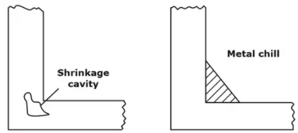
(c) Chills
Chills are metallic objects which is placed in the mould to increase the cooling rate of castings to provide uniform or desired cooling rate.
Pads or Padding
At the corner, due to improper ramming, there is always chances of erosion of sand When the molten metal is filled in mould cavity.
To avoid this, some objects are provided at the corner to support the mould which is known as pad & this process is known as padding.
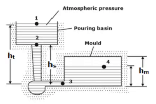
Gating System
In the casting process, to avoid the oxidation, the molten metal is always poured in to casting cavity using a system called as gating system. It consists of four basic elements
- Pouring basin
- Sprue
- Runner
- Ingate
Gating Ratio
The gating ratio refer to the proportion of the cross-sectional areas between the sprue, runner and in-gates, and is generally denoted as sprue area, runner area, and ingate area.
Gating ratio = Ratio of (sprue area: runner area: ingate area)
Gating ratio = AS: AR: AG
Casting Yield
The casting yield is the proportion of the actual casting mass, m, to the mass of metal poured into the mould M.
Casting yield = m/M x 100
Choke Area
It is also the minimum area in whole gating system (sprue area, runner area, ingate area).
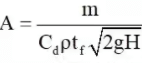
where H = effective metal head (sprue height), mm
Non-pressurized Gating System
A non-pressurized gating system has choke area (minimum area) at the bottom of the sprue base and have total runner area and in-gate areas higher than the sprue area.
Pressurized Gating System
In this system, the smallest area is the in-gate area and thus it maintains a back pressure throughout the gating system.
Top Gating System
In top gating, the liquid metal is poured directly from the sprue to mould cavity with atmospheric pressure at the base.
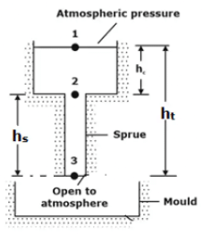
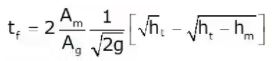
(i) Pouring or filling time for Top Gating
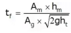
where,
ht =total height
hm=height of the mould
Special case:
If height of the mould(hm) is equal to total height (ht).
(tf)Bottom = 2 x (tf)Top
Solidification time
“It is the time required for the casting to solidify after pouring” and this time is dependent on the size and shape of the casting.
Solidification time is given by Chvorinov's rule:
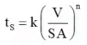
Where,
ts = total solidification time
k = mould constant (or) solidification factor
V = volume of the casting,
SA = surface area of the casting,
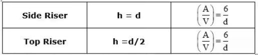
It is the ratio of volume to surface area of any casting. This formula is applicable for risers also.
M = V/SA
Methods of Riser Design
1. Caine’s Method
This method can be used to calculate the dimensions of the Riser for the simple shape of the castings.
2. Shape factor method
Shape factor, (S.F.) = (L + w) / t
|
56 videos|80 docs|29 tests
|
FAQs on Metal Casting Processes - Manufacturing Engineering - Mechanical Engineering
| 1. What is metal casting? |  |
| 2. What are the different types of metal casting processes? | |
| 3. How does sand casting work? | |
| 4. What is investment casting? | |
| 5. What are the advantages of metal casting processes? | |


Sample Paper
,video lectures
,Metal Casting Processes | Manufacturing Engineering - Mechanical Engineering
,Exam
,Free
,mock tests for examination
,ppt
,Extra Questions
,Summary
,study material
,Metal Casting Processes | Manufacturing Engineering - Mechanical Engineering
,Metal Casting Processes | Manufacturing Engineering - Mechanical Engineering
,practice quizzes
,Important questions
,Previous Year Questions with Solutions
,MCQs
,Viva Questions
,Objective type Questions
,past year papers
,shortcuts and tricks
,Semester Notes
;


Metal Casting Processes Free PDF Download
Importance of Metal Casting Processes
Metal Casting Processes Notes
Metal Casting Processes Mechanical Engineering Questions
Study Metal Casting Processes on the App
|
© EduRev
|
Education Revolution
|


|


