Computer Integrated Manufacturing | Manufacturing Engineering - Mechanical Engineering PDF Download

Introduction
Computer Integrated Manufacturing is the manufacturing approach of using computers to control the entire production process. Individual processes exchange information with each other and initiate actions with the help of this integration. Factory floor functions such as materials handling and management, providing direct control and monitoring of all the operations are linked with functional areas such as design, analysis, planning, purchasing, cost accounting, inventory control, and distribution in a CIM system.
Processes Involved
- A list of different processes involved is given below:
- Computer-Aided Design
- Prototype manufacturing
- Determination of the efficient method for manufacturing by calculation of the costs and considering the production methods, volume of products, storage and distribution
- Giving order of the necessary materials required for the production process
- Computer-aided manufacturing of the products with the help computer numerical controllers
- Quality controls at each of the development.
- Product assembly with the help robots
- Quality check and automated storage
- Distribution of products to awaiting lorries/trucks from the storage areas automatically
- Updating of logs, financial data and bills in the computer system automatically.
Why Cim?
- Error Reduction: Elimination of human error in many assignment and reporting functions on factory floor operation drastically reduces the error rate.
- Speed: Quicker flow of product to customers and increased capacity, reduction in the time taken to perform manufacturing, fabrication and assembly is possible in a CIM environment.
- Flexibility: With CIM companies quickly react to market conditions and then return to previous setting when market condition change.
- Integration: A degree of introduction of integration of flexibility, speed and error reduction is offered by a CIM which is required to compete and lead markets. Integration of factory floor operations with enterprise software enables employees to do higher value functions for their companies.
Usages of Cim
- Industrial and Production Engineering
- Mechanical Engineering
- Electronic Design Automation
(i) Printed Circuit Board design
(ii) Integrated Circuit design
Machine
Conversion of one form of energy into another is possible by a machine. Machine which performs multiple operation is known as machine centre. Tool Magazine is used to store the tool for machine centre.
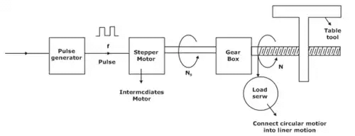
NC (Numeric Control) (Open Loop Control)
The directions of tool motions are controlled by alphabets and using number is known as Numeric Control. It is a programmable automation in which the program is installed in the form of presence and absence of holes on the punch card. Punch cards are prepared by using paper or plastic tapes.
- Tape reader is used to read the punch card and generate the electric pulses using pulse generator.
- Stepper motor rotor at a speed of Ns (steps per resolution) offer receiving the electronic signal form the pulse generator. Stepper motor is connected with the lead screw with the help of a gear box to provide the desired speed.
- Lead screw converts rotation into livers motion.
Lamination of NC
- There is no feedback loop control.
- Legibility to modify the program is zero.
- Lengthy topes are used and it very laborious and time taken.
Stepper Motors
These are used for precise positioning of objects or machines slide out using a feedback control system. Stepper motor is driven by an electrical pulse train operated by the machine control unit. Rotation of the motor shaft is proportional to number of pulses it receives, and its angular velocity is proportional to the frequency of pulses. A stepper motor rotates a precise angular distance, i.e., one step for each pulse it receives. Each pulse turns the shaft by a fraction of one revolution, called the step angle.
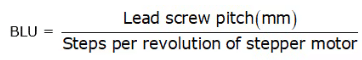
Basic Length Unit (BLU)
It is the distance travelled by the table for one step or pulse of stepping motor. where
Also, linear velocity of stepper motor, V is given by the expression
V = pulse frequency x BLU x 60 mm/min
CNC (Computer Numeric Control) (Closed Loop CNC)
It is a programmable automation in which program is installed in microprocessor. Programs are written using NC programming as before. The feedback signal from the table tool movement. Comparator compare the single from encode and from the pulse generator.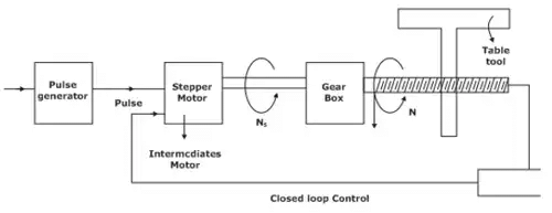
Direct Numerical Control (DNC)
In 70’s the size of hardware was quite big. External computes were used to store the complex programs which is directly comely commented to the machine.
Distributed Numeric Control (DNC)
It is used to control multiple machines at different location using single computer.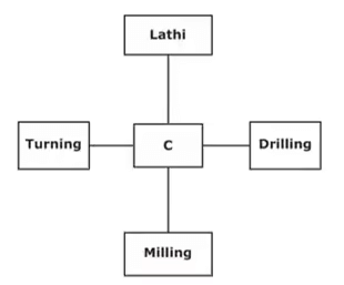
Flexible Machining System (FMS)
Automating the entire manufacturing system with negligible manual intervention. A group of machines interconnected together using automated material handling and storage system controlled by integrated computer system is contained by a FMS.
Automated Guided Vehicles (AGV)
They are used to transfer the work material from one machine to the work station to the another.
Preparatory Functions
This is denoted by ‘G’. Movement of machine axes and the associated geometry, these functions are associated with this pre-set function. As discussed, it has two digits, e.g. G01, G42 and G90, as per ISO specifications. However, some of the current-day controllers accept up to 3 or 4 digits. In this we will only discuss some of the regular functions. A number of preparatory functions, also popularly called G codes have been standardized by the ISO. The standardized codes are shown below: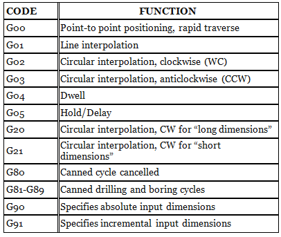
Miscellaneous Functions, M
These functions operate few controls on the machine tool and hence may affect the running of the machine. The ISO standard M codes are shown below: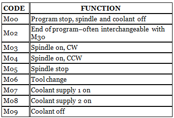
Interpolator
In a number of machining situations, tool has to move along continuous curves. The problem in generating these curves with NC is that trajectory is continuous while NC is digital. So the tool cannot trace exactly the desired path. The NC controller has to calculate large number of closely spaced points on the cutter path. These points are connected by very small straight lines to form the trajectory. If these points are very closely spaced, the actual path traced becomes approximately same as the desired tool path. The minimum distance between two points that the machine can differentiate is called control resolution. The accuracy of the machine depends on the control resolution. The process of calculating the points on the trajectory is called interpolation. A number of interpolation algorithm have been developed to generate smooth continuous tool trajectory with contouring type NC system. These are
- Linear Interpolator: It is a program /algorithm which can calculate closely spaced points between the given end points of line.
- Circular Interpolator: This is an algorithm that generates closely spaced points on the arc or circular profile which when connected by straight lines approximates a circle. The moves from point to point in order to machine a circular cut.
- Helical Interpolator: It is an algorithm that contains the logic of circular interpolation and linear interpolation perpendicular to the plane of circle to form a helical path.
- Parabolic Interpolator: It is less common in use. It can make use of the parabolic equation to generate points on parabolic curve.
|
56 videos|80 docs|29 tests
|
FAQs on Computer Integrated Manufacturing - Manufacturing Engineering - Mechanical Engineering
| 1. What is Computer Integrated Manufacturing (CIM) in Mechanical Engineering? |  |
| 2. How does Computer Integrated Manufacturing benefit the Mechanical Engineering field? | |
| 3. What are the key components of Computer Integrated Manufacturing in Mechanical Engineering? | |
| 4. How does Computer Integrated Manufacturing impact the efficiency of production in Mechanical Engineering? | |
| 5. What are the challenges faced in implementing Computer Integrated Manufacturing in Mechanical Engineering? | |


MCQs
,shortcuts and tricks
,practice quizzes
,Computer Integrated Manufacturing | Manufacturing Engineering - Mechanical Engineering
,Sample Paper
,Viva Questions
,video lectures
,Computer Integrated Manufacturing | Manufacturing Engineering - Mechanical Engineering
,Semester Notes
,mock tests for examination
,Extra Questions
,Objective type Questions
,Summary
,ppt
,Computer Integrated Manufacturing | Manufacturing Engineering - Mechanical Engineering
,Important questions
,past year papers
,study material
,Exam
,Previous Year Questions with Solutions
,Free
;


Computer Integrated Manufacturing Free PDF Download
Importance of Computer Integrated Manufacturing
Computer Integrated Manufacturing Notes
Computer Integrated Manufacturing Mechanical Engineering Questions
Study Computer Integrated Manufacturing on the App
|
© EduRev
|
Education Revolution
|


|


