Limits, Fits & Tolerance


Metrology and Inspection
Metrology is the science of measurement. It covers the design, manufacture, selection and application of measuring instruments and techniques used to control the dimensions of manufactured components. Good metrology ensures accurate dimensional control, traceability and interchangeability of parts produced in quantity.
Interchangeability
Interchangeability is the principle used in mass production to make large numbers of identical parts so that any part will fit and function with any mating part within specified limits. Interchangeability reduces assembly time, repair time and inventory complexity.
- Full (Universal) Interchangeability - Every part produced fits any mating part without sorting.
- Selective Assembly - Parts are measured and selectively paired so that each assembled pair meets functional requirements.
- Matched Fits - Specific pairs are matched during assembly; interchangeability is limited to those matched pairs.
Limit System
The limit system defines the permissible maximum and minimum sizes of a feature. The main terms used are listed and explained below.
- Nominal Size
The size by which a part is designated as a matter of convenience. For example, when we say a 25 mm pipe we mean a pipe designated as 25 mm nominal diameter. - Basic Size
The theoretical size common to both members of a mating pair (for example, a hole and a shaft). - Actual Size
The size that a finished part actually attains after manufacturing and inspection. - Allowance
(i) Allowance is the intentional difference between the dimensions of mating parts.
(ii) Numerically, it is the difference between the lower limit of the hole and the upper limit of the shaft.
(iii) Allowance represents the minimum clearance (positive) or maximum interference (negative) between mating parts. - Tolerance
(i) The difference between the upper limit and the lower limit of a dimension.
(ii) The maximum permissible variation in the size of a feature.
(iii) Tolerance may be provided in two basic forms: unilateral or bilateral.
Unilateral limits
Variation in size is permitted in only one direction from the basic size; the tolerance zone lies entirely on one side of the basic size.
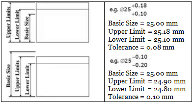
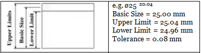
Bilateral limits
Variation in size is permitted on both sides of the basic size; the tolerance zone straddles the basic size.
Deviation
- Zero Line
The reference line corresponding to the basic size. All deviations are measured from the zero line. - Deviation
The algebraic difference between any actual size and the corresponding basic size. - Actual Deviation
The algebraic difference between the actual measured size and the basic size. - Upper Deviation
The algebraic difference between the maximum permitted size and the basic size. - Lower Deviation
The algebraic difference between the minimum permitted size and the basic size. - Mean Deviation
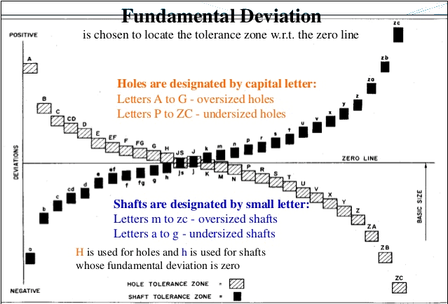
The arithmetic mean of the upper and lower deviations. - Fundamental Deviation
The deviation (either upper or lower) nearest to the zero line for either the hole or the shaft; it establishes the position of the tolerance zone relative to the basic size.
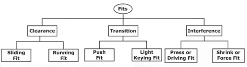
Fits
A fit describes the relationship between mating parts (a hole and a shaft) and specifies whether clearance or interference occurs on assembly. The degree of fit determines assembly method and function.
Hole Basis System
- Clearance Fit
Occurs when the lower limit of the hole is greater than the upper limit of the shaft; there is always a clearance between parts.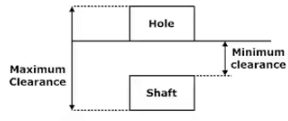
- Interference Fit
Occurs when the lower limit of the shaft is greater than the upper limit of the hole; there is always interference and parts must be assembled by force, heating/cooling, or pressing.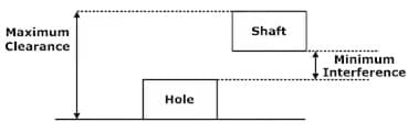
- Transition Fit
Occurs when some random pairs from production may give clearance and some may give interference; assembly may require judgement whether press fit or light clearance is present.
Indian Standard System (IS)
Standard tolerances for various tolerance grades are given by Indian Standards. The magnitudes of standard tolerances corresponding to grades IT01, IT0 and IT1 are provided by empirical formulae (D in mm):
IT01 = 0.3 + 0.008D
IT0 = 0.5 + 0.012D
IT1 = 0.8 + 0.020D
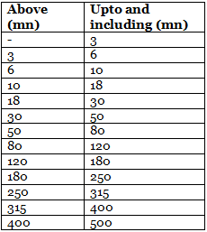
The fundamental tolerance unit i and tables of limits for different nominal size ranges are given in the standard reference tables.
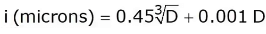
The value of D used in these expressions is the size or geometric mean diameter in mm. The two limits for calculating D are taken from the relevant standard tables for the size range.
Limit Gauges
Limit gauges are scaleless inspection tools used to verify whether a manufactured part lies within its specified limits. They are simple, rapid and suitable for production inspection where binary (go / no-go) decision is required.
Main forms of limit gauges:
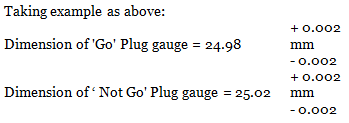
- Plug Gauge
The GO plug gauge corresponds to the lower limit of the hole and must enter the hole fully. The NO GO plug gauge corresponds to the upper limit of the hole and must not enter the hole.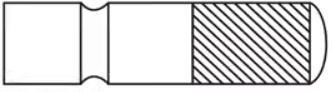 Plug gauge
 - Ring Gauge
Used for checking external diameters such as shafts. Snap, gap or ring gauges are used for gauging male components.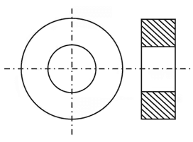 Ring gauge
 - Slip Gauges (Gauge Blocks)
Rectangular or parallelepiped blocks made with extremely high accuracy and flat, parallel faces. They are available in a range of lengths and are used for setting up and calibrating instruments and for precision measurements.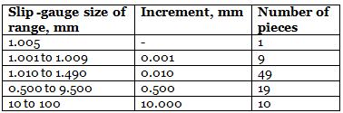
Gauge Design
- Inspection gauge
- Workshop gauge
- ISO / General purpose gauge
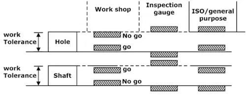
Gauge Systems
Unilateral system
- The gauge tolerance zone is entirely under the work tolerance zone.
- The effective working tolerance becomes less than the sum of the gauge tolerances.
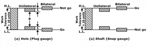
Bilateral system
In the bilateral system the GO and NO GO gauge tolerance zones are bisected by the upper and lower limits of the work tolerance zone.
Linear Measurements
Common instruments for linear measurements (from shop floor to laboratory) include:
- Rules (steel rule)
- Vernier caliper
- Micrometre
- Height gauge
- Bore gauge
- Dial indicator
- Slip gauges or gauge blocks
Angular Measurements
Angular measurement is required for tapers, setting angles and assessing angular features. Common tools include the bevel protractor and sine bar.
- Bevel Protractor
Part of the machinist's combination set. The flat base sits on the workpiece and a rotatable graduated blade measures the angle. Typical discrimination is 1°; with vernier attachments it can be much finer. - Sine Bar
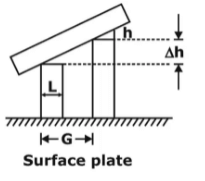
The sine bar is a precision bar with two centres (cylindrical rollers) at a fixed distance apart. The distance between the centres is fixed for a particular sine bar and is usually stamped on the bar.
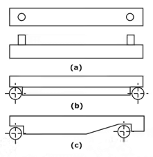
Now, if θ is the angle subtended by the lower face of the sine bar with the datum surface (top of the surface plate), and the sine bar is supported on gauging slips of total height h, then the relationship between the angle and the slip-gauge height is derived as follows.
 Use of sine bar
Distance between the centres = L.
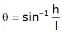
Using geometry of the sine bar:
h = L × sinθ
Therefore, sinθ = h ÷ L
For a required angle θ prepare slip gauge height h = L × sinθ using appropriate combination of gauge blocks.
Measurement Over Wires
Measurement-over-wires is a technique used to measure the pitch diameter of external cylindrical features such as threads or gear teeth by placing wires of known diameter across the feature and measuring the distance over them.
In the figure the pitch diameter is related to the measured quantity by the relation:
Pitch diameter, DP = M + P
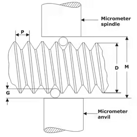 Thread measuring using micrometer
Exact expressions and the geometry depend on the feature profile and wire placement; consult the figure for definitions of symbols M and P used in that illustration.
Three-Wire System
The three-wire method is commonly used to measure the pitch diameter of external screw threads accurately. Three wires are placed in the thread grooves and the distance over the wires is measured with a micrometre. A correction factor depending on wire diameter and thread geometry is applied to obtain the pitch diameter.
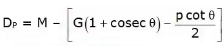
The best wire diameter for a given thread is selected to minimise the error; the selection rules and formulae are shown in the referenced figure.

Optical Flat As Comparator
An optical flat is a high-quality transparent disk with an accurately flat lower surface used as a comparator. When placed on a surface and illuminated, interference fringes form; the fringe pattern reveals departures from flatness. Optical flats are also used with master references to calibrate gauge-block stacks.
To determine the difference Δh between heights using an optical flat and reference, similar triangles from the fringe geometry give the relation (refer to the figure for geometry and symbol definitions):
Therefore:
∆h = (n λ / 2) × (G / L)
where
n = number of interference fringes
λ = wavelength of light
G = fringe spacing
L = reference length
h = λ/2 = height corresponding to one fringe
Use the figure to identify each symbol and apply the formula accordingly.
Surface Finish (Surface Texture)
The actual surface obtained after machining shows microscopic deviations - a series of peaks and valleys - even when it appears smooth to the eye. The surface texture has three principal components: roughness (small, closely spaced deviations), waviness (larger, spaced deviations), and form error (larger scale departures from intended geometry).
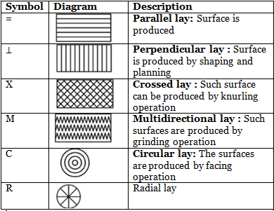
Lay Direction
Lay is the predominant direction of the surface pattern produced by a manufacturing process (for example, circumferential lay on a turned surface or cross lay on a milled surface). The common lay types are shown in the figure.
Evaluation of Surface Roughness
Common parameters used to quantify surface roughness include the arithmetic mean roughness RA, the root-mean-square roughness Rrms, and the peak-to-valley height RT (also Rmax).
Arithmetic average (Center Line Average) RA
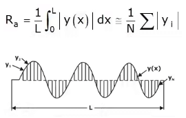 Surface roughness parameters
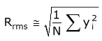
Root mean square value Rrms
The root-mean-square value of the surface deviation is sometimes used instead of the arithmetic average. The expression is shown in the figure.
Peak-to-Valley Height (RT or Rmax)
RT is the difference between the highest peak and the deepest valley within the evaluation length.
An approximate relationship between RA and maximum peak height Hamx for certain tool-generated profiles is:
RA ≈ Hmax ÷ 4
Maximum height of unevenness for a cutting tool with nose radius R and feed f may be approximated by:
Hmax = f² ÷ (8R)
If the complete tool signature is given, the peak-to-valley height can be calculated from the tool geometry and cutting parameters; the relevant expression and diagram are shown in the figure.
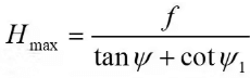
Where:
- f = feed per revolution or feed per tooth as applicable
- Ψ = side cutting edge angle
- Ψ1 = end cutting edge angle
Practical Notes and Applications
- Choose tolerances based on functional requirements and manufacturing capability; tighter tolerances increase cost and inspection complexity.
- Select the appropriate fit (clearance, transition, interference) depending on assembly method and functional demands (rotating fit, fixed assembly, locating fit etc.).
- Use limit gauges for rapid shop-floor inspection; use calibrated measuring instruments and gauge blocks for dimensional calibration and calibration chains.
- Apply the sine bar, three-wire and optical-flat methods where direct measurement is difficult; follow the diagrams and formulae precisely to convert measured quantities to required parameters.
- Control surface finish by selecting suitable cutting tools, feeds, speeds and finishing operations; specify surface roughness parameters (RA, RT, lay) on engineering drawings.
Summary
This chapter presents the fundamental concepts used in dimensional control: interchangeability, limit and deviation systems, fits, standard tolerance grades, limit gauges and common measurement techniques including sine-bar and three-wire methods. It also covers surface texture, its measurement and practical formulas linking machining parameters to surface roughness. Use the figures and standard tables shown throughout to apply the formulae and to select fits, tolerances and gauges for design and inspection tasks.
FAQs on Limits, Fits & Tolerance
| 1. What is metrology and why is it important in mechanical engineering? |  |
| 2. What are limits, fits, and tolerance in mechanical engineering? | |
| 3. How are limits and fits classified in mechanical engineering? | |
| 4. What are the common measurement techniques used in metrology and inspection? | |
| 5. What are the challenges in metrology and inspection in mechanical engineering? | |


